Intermec 203-880-002 User manual

Forklift Power Supply
Installation
Guide

ii Forklift Power Supply Installation Guide
Intermec Technologies Corporation
Worldwide Headquarters
6001 36th Ave.W.
Everett, WA 98203
U.S.A.
www.intermec.com
The information contained herein is provided solely for the purpose of allowing
customers to operate and service Intermec-manufactured equipment and is not to be
released, reproduced, or used for any other purpose without written permission of
Intermec Technologies Corporation.
Information and specifications contained in this document are subject to change
without prior notice and do not represent a commitment on the part of Intermec
Technologies Corporation.
© 2008-2009 by Intermec Technologies Corporation. All rights reserved.
The word Intermec, the Intermec logo, Norand, ArciTech, Beverage Routebook,
CrossBar, dcBrowser, Duratherm, EasyADC, EasyCoder, EasySet, Fingerprint, INCA
(under license), i-gistics, Intellitag, Intellitag Gen2, JANUS, LabelShop, MobileLAN,
Picolink, Ready-to-Work, RoutePower, Sabre, ScanPlus, ShopScan, Smart Mobile
Computing, SmartSystems, TE 2000, Trakker Antares, and Vista Powered are either
trademarks or registered trademarks of Intermec Technologies Corporation.
There are U.S. and foreign patents as well as U.S. and foreign patents pending. Wi-Fi is
a registered certification mark of the Wi-Fi Alliance.

Forklift Power Supply Installation Guide iii
Document Change Record
This page records changes to this document. The document was
originally released as Revision 001.
Version
Number Date Description of Change
002 6/2009 Updated to include new printer models
and output cable number.
001 4/2008 First release of document

iv Forklift Power Supply Installation Guide

Contents
Forklift Power Supply Installation Guide v
Contents
Before You Begin . . . . . . . . . . . . . . . . . . . . . . . . . . . . . . . . . . . . viii
Safety Information . . . . . . . . . . . . . . . . . . . . . . . . . . . . .viii
Global Services and Support . . . . . . . . . . . . . . . . . . . .viii
Warranty Information . . . . . . . . . . . . . . . . . . . . viii
Web Support . . . . . . . . . . . . . . . . . . . . . . . . . . . . . . ix
Telephone Support . . . . . . . . . . . . . . . . . . . . . . . . ix
Service Location Support. . . . . . . . . . . . . . . . . . . ix
Who Should Read This Manual . . . . . . . . . . . . . . . . . . .x
1 Introduction . . . . . . . . . . . . . . . . . . . . . . . . . . . . . . . . . . 1
Understanding the DC Power Supply Kit . . . . . . . . . . . . . . . 2
Installation Guidelines . . . . . . . . . . . . . . . . . . . . . . . . . . . . . . . 2
Power Supply Considerations . . . . . . . . . . . . . . . . . . . . . . . . . 3
Understanding Power Supply LEDs . . . . . . . . . . . . . . 3
Using the Input Power Cable. . . . . . . . . . . . . . . . . . . . . 4
Using the Inline Fuse. . . . . . . . . . . . . . . . . . . . . . . . . . . . 5
Using the Output Power Cable . . . . . . . . . . . . . . . . . . . 6
Contents of the Forklift Power Supply Kit . . . . . . . . . . . . . . 6
Wiring Diagram. . . . . . . . . . . . . . . . . . . . . . . . . . . . . . . . . . . . . . 8
2 Installing the Forklift Power Supply . . . . . . 9
Installation Recommendations . . . . . . . . . . . . . . . . . . . . . . . 10
Installation Overview. . . . . . . . . . . . . . . . . . . . . . . . . . . 10
Tools List . . . . . . . . . . . . . . . . . . . . . . . . . . . . . . . . . . . . . 11
Preparing the Power Input Cable . . . . . . . . . . . . . . . . . . . . . 11
Mounting the Power Supply. . . . . . . . . . . . . . . . . . . . . . . . . . 11
Direct Versus Isolation Mounting on the
Lift Chassis . . . . . . . . . . . . . . . . . . . . . . . . . . . . . . . . . 12
Creating a Custom Electrical Isolation Mount. . . . 13
Using a Standard Power Supply Mount . . . . . . . . . . 14

Contents
vi Forklift Power Supply Installation Guide
Installing the Input Power Cable. . . . . . . . . . . . . . . . . . . . . . 14
Connecting the Power Cable to the Forklift. . . . . . . . . . . . 15
Terminating the Input Cable . . . . . . . . . . . . . . . . . . . . . . . . . 16
Cutting and Stripping the Input Power Cable . . . . 16
Attaching Heat Shrink Tubing . . . . . . . . . . . . . . . . . . 17
Preparing the Cable Ends . . . . . . . . . . . . . . . . . . . . . . . 18
Connecting to the Forklift Battery . . . . . . . . . . . . . . . . . . . . 19
Connecting to Side-Mount Battery Terminals . . . . 19
Connecting to Top-Mount Battery Terminals . . . . 20
Securing the Battery Cable . . . . . . . . . . . . . . . . . . . . . . 21
Connecting the Output Power Cable . . . . . . . . . . . . 21
Sample Installations . . . . . . . . . . . . . . . . . . . . . . . . . . . 22
3 Troubleshooting . . . . . . . . . . . . . . . . . . . . . . . . . . . . 25
Identifying and Correcting Problems. . . . . . . . . . . . . . . . . . 26
Inspecting the Hardware. . . . . . . . . . . . . . . . . . . . . . . . 26
Checking the Electrical Measurements. . . . . . . . . . . 26
Measuring the Voltage . . . . . . . . . . . . . . . . . . . . 26
Performing Continuity Testing . . . . . . . . . . . . 26
Substituting Components . . . . . . . . . . . . . . . . . . . . . . 27
Troubleshooting Charts . . . . . . . . . . . . . . . . . . . . . . . . . . . . . 27

Contents
Forklift Power Supply Installation Guide vii

Before You Begin
viii Forklift Power Supply Installation Guide
Before You Begin
This section provides you with safety information, technical
support information, and sources for additional product
information.
Safety Information
Your safety is extremely important. Read and follow all warnings
and cautions in this document before handling and operating
Intermec equipment. You can be seriously injured, and
equipment and data can be damaged if you do not follow the
safety warnings and cautions.
This section explains how to identify and understand warnings,
cautions, and notes that are in this document.
Global Services and Support
Warranty Information
To understand the warranty for your Intermec product, visit the
Intermec web site at www.intermec.com and click Support >
Returns and Repairs > Warranty.
A warning alerts you of an operating procedure, practice,
condition, or statement that must be strictly observed to
avoid death or serious injury to the persons working on the
equipment.
A caution alerts you to an operating procedure, practice,
condition, or statement that must be strictly observed to
prevent equipment damage or destruction, or corruption or
loss of data.
Note: Notes either provide extra information about a topic or
contain special instructions for handling a particular condition
or set of circumstances.

Before You Begin
Forklift Power Supply Installation Guide ix
Disclaimer of warranties: The sample code included in this
document is presented for reference only. The code does not
necessarily represent complete, tested programs. The code is
provided “as is with all faults.” All warranties are expressly
disclaimed, including the implied warranties of merchantability
and fitness for a particular purpose.
Web Support
Visit the Intermec web site at www.intermec.com to download
our current manuals (in PDF). To order printed versions of the
Intermec manuals, contact your local Intermec representative or
distributor.
Visit the Intermec technical knowledge base (Knowledge Central)
at www.intermec.com and click Support > Knowledge Central
to review technical information or to request technical support
for your Intermec product.
Telephone Support
In the U.S.A. and Canada, call 1-800-755-5505.
Outside the U.S.A. and Canada, contact your local Intermec
representative. To search for your local representative, from the
Intermec web site, click About Us > Contact Us.
Service Location Support
For the most current listing of service locations, go to
www.intermec.com and click Support > Returns and Repairs
> Repair Locations.
For technical support in South Korea, use the after service
locations listed below:
AWOO Systems
102-1304 SK Ventium
522 Dangjung-dong
Gunpo-si, Gyeonggi-do Korea, South 435-776
Contact: Mr. Sinbum Kang
Telephone: +82-31-436-1191
E-mail: [email protected]

Before You Begin
x Forklift Power Supply Installation Guide
IN Information System PTD LTD
6th Floor
Daegu Venture Center Bldg 95
Shinchun 3 Dong
Donggu, Daegu City, Korea
Who Should Read This Manual
This document is for the person who is responsible for installing,
configuring, and maintaining the Forklift Power Supply. The
Forklift Power Supply Installation Kit can be used with the PB21,
PB22, PB31, PB32, PB50, PB51, and PW50 mobile printers.
This document provides you with information about the
features of the forklift power supply, and how to install,
configure, operate, maintain, and troubleshoot it.
Before you work with the forklift power supply , you should be
familiar with your network and general networking terms, such
as IP address.


Chapter 1 — Introduction
2 Forklift Power Supply Installation Guide
Understanding the DC Power Supply Kit
Use the DC power to help supply power to your mobile printer
when it is on a forklift. The DC power supply kits include these
items:
•Power supply
•Power supply input cable, 2.44 m (8 feet)
•Fused power cable, 46 cm (18 inch)
•#10 terminal ring
•3AB, 20A/250 Vx fuse for 12 V installations
•Insulated quick-connect tabs (2)
The power supply provides 12 Vx output that is filtered and
regulated. It also provides over-current, over-voltage, over
temperature, and shorted-output protection.
Installation Guidelines
You should be familiar with the brands and models of
equipment where this kit is installed. You should also be trained
and experienced in forklift electrical systems.
Follow these guidelines and the installation procedures as well as
those of the lift manufacturer to ensure a safe and reliable
installation:
•Make sure the power supply is securely mounted.
•Make sure the mounting surface is sturdy.
•Make sure the mounting surface provides power supply heat
sink.
•Make sure the fuse is close to vehicle power source and is in
line with Intermec equipment only.
•Keep cables as short as possible, and secure them at least
every 46 cm (18 inch).
Before installing the power supply, familiarize yourself with the
forklift manufacturer’s requirements and make sure you have the
proper qualifications to perform the installation. For procedures
on how to properly mount the forklift power supply, see
“Mounting the Power Supply” on page 11.

Chapter 1 — Introduction
Forklift Power Supply Installation Guide 3
Order the Smart UPS kit (P/N 203-788-xxx) for a universal power
supply (UPS) that provides backup power during battery change
out.
Power Supply Considerations
Follow these guidelines when installing the power supply:
•The power supply (P/N 851-070-003) accepts input voltage
ranging from 6 to 60 Vx for use with forklifts using electrical
systems running 12 to 60 Vx. It provides 12 Vx output which
is filtered and regulated. It also provides short-circuit, over-
voltage, and over-temperature protection.
•You should mount the power supply to the forklift chassis or
connect it (electrically) through external wire to the forklift
chassis. Chassis ground to the printer or other equipment is
then established through the power supply output cable.
•Since the power supply produces heat, Intermec advises that
you mount it on a metallic surface that is a minimum of 838
to 1032 square cm (130 to 160 square inches which is
approximately one square foot or more) to disperse heat.
This location should not be in the vicinity of sources of
forklift generated heat.
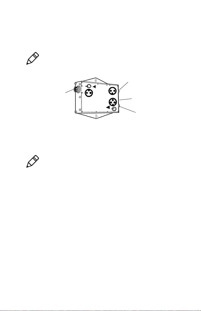
Understanding Power Supply LEDs
A single or a pair of green light-emitting diodes (LEDs), located
near the output connectors on the power supply
(P/N 851-070-003), light up whenever you apply voltage to the
output power cable. Mount the power supply in a location that
allows easy visibility to LEDs for troubleshooting.
Note: This document assumes that you have already installed
the vehicle mount printer on your forklift and that you have the
correct power supply and power supply input cable for your
forklift before you proceed with the installation.
Note: Use the hardware supplied in the kit, or equivalent, to
mount the power supply. Do not use sheet metal screws or other
less permanent or rugged mounting solutions.
Chapter 1 — Introduction
4 Forklift Power Supply Installation Guide
The main output LED indicate that the main power is
functioning (3-pin connector). The secondary power LED
indicates the heater power (2-pin connector) is functioning.
Power Supply LED
Using the Input Power Cable
The input cable from the power supply is approximately 2.74 m
(9.0 feet) long. One end has a 4-pin connector, the other has a 2-
pin connector. By cutting off the unneeded connector, a single
cable can meet either 4 or 4.5 A current requirements. The cut
end is then terminated for connection to the forklift power
source. For instructions on attaching the power cable, see
“Mounting the Power Supply” on page 11.
Note: If the secondary LED is not lit, the input power to the
DC-DC converter is less than 9 to 10 Vx. It will continue to
provide 12 V output power to the main power connector.
Output connector
(secondary power)
Green LEDs
(power output indicators)
Output connector
(main power)
Input connector
Note: Keep the cable as short as possible. Extra cable picks up
noise, adds power loss, and can snag on equipment.
The input power cable may be shortened as needed. It should
not be extended on 12 V or lower systems. On higher voltage
systems, extensions should be kept to a minimum and should
be of equivalent or lower gauge (larger diameter) wire. Keep the
cable as short as possible. Extra cable picks up noise, adds power
loss, and can snag on equipment.

Chapter 1 — Introduction
Forklift Power Supply Installation Guide 5
Using the Inline Fuse
A snap-twist inline fuse holder is furnished as part of this kit. It
must be connected as close as possible (electrically and
physically) to the forklift power source. It provides catastrophic
failure, short-circuit protection for the entire input power cable
and the power supply input. The fuse holder contains a 3AB, 20
A/250 Vx (.25 inch x 1.25 inch) fast-blow fuse recommended for
installations with 12 V automotive batteries. For other vehicle
battery voltages, please refer to the table below. These alternate
fuses are not provided with the kit and must be obtained
separately. In general, smaller fuse ratings offer faster acting
protection.
Note: If your fuse fails, diagnose the problem and then correct it
before replacing the fuse with the exact same size and type you
are replacing.
Recommended Fuse Values
Lift Voltage Fuse Ratings Description
12V 20A Fast-blow (ships with power
supply)
24V 10A Slow-blow, maximum fuse value
36V 6A Slow-blow, maximum fuse value
48V 5A Slow-blow, maximum fuse value
Do not replace the fuse with larger fuse values than
recommended. Use of a larger fuse may result in damage to
equipment.

Chapter 1 — Introduction
6 Forklift Power Supply Installation Guide
Using the Output Power Cable
Output power cables (P/N 236-193-001) are approximately 2.2 m
(7.2 feet) long and have a durable 2-pin connector to mate with
the power supply. The connector on the far end of the cable is
specific to the vehicle cradle for the printer. These rugged
connectors have heavy-duty metal housings and enhanced strain
relief to provide added reliability in the mobile environment. For
a diagram of the output cable, see the next section.
Contents of the Forklift Power Supply Kit
Installing the Printer With the Forklift Power Supply Kit
Note: Ensure that you have the correct output power cables for
the mobile printer you are installing.
Contents of Forklift Power Kit (P/N 203-880-002)
Description Part Number Quantity
Installation kit, vehicle power
supply
203-804-002 1
DC/DC converter 6-60 Vin/12
Vout (power supply)
851-070-003 1
Vehicle dock (AV8) forklift cable
(output cable)
236-193-003 1
Forklift Power Supply
Installation Guide
932-011-xxx 1
6-60 V
Fuse
Printer
and vehicle cradle
Cable input
DC/DC power supply
(“converter”)
Cable output
-
-
+

Chapter 1 — Introduction
Forklift Power Supply Installation Guide 7
Cable assembly (input cable) 226-340-004 1
Fuse holder assembly 315-075-003 1
Fuse, 20 A ceramic FB 315-074-003 1
Bolt, 3/8-16 x 1-1/2-inch 800-099-001 2
Washer, 3/8-inch 803-099-001 4
Nut, 3/8-16 802-099-001 4
Adjustable wire clamps 808-011-001 8
Self-tap screw #6 x 5/8-inch 800-008-003 8
3/8-inch terminal ring 809-165-001 2
#10 terminal ring 809-083-009 3
Self-tapping screw, 800-012-000 1
#8 flat washer 803-084-000 1
Snap-in bushing 807-065-003 1
Screw, 1/4-20 x 1-1/4 inch 801-194-002 2
Flat washer 803-100-001 2
Locking nut 802-117-000 2
Washer, split-lock 803-042-001 2
Cable tie, locking 808-002-000 6
H-S tubing, black, 1/8-inch
diameter
321-650-003 30.5 cm
H-S tubing, black, 3/8-inch
diameter
321-650-006 15.2 cm
Bead, split w/sleeve 309-065-006 1
Plug, 2-socket circular 311-638-00 1
Plug, 4-socket circular 311-638-
006 1
311-638-006 1
Cable, 4 cond 18 AWG, foil-
shielded
321-295-005 274.3 cm
Shield bead, .590/.275/1.10L,
300HM 309-091-008 2
309-091-008 2
Contents of Forklift Power Kit (P/N 203-880-002) (continued)
Description Part Number Quantity
Chapter 1 — Introduction
8 Forklift Power Supply Installation Guide
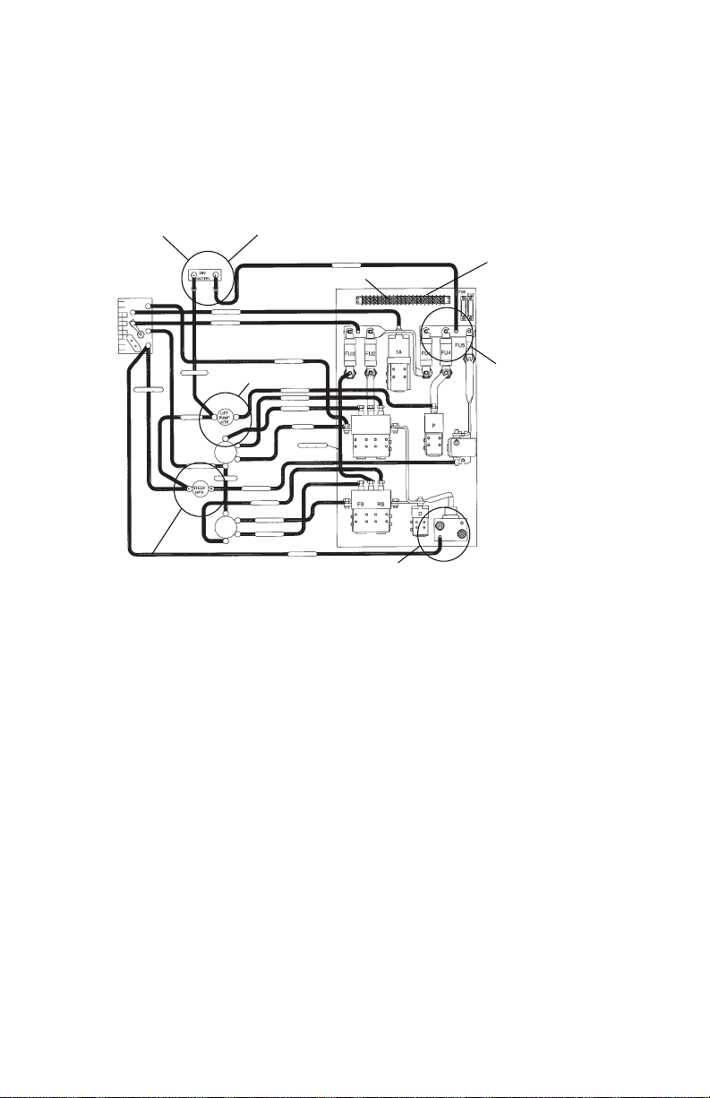
Wiring Diagram
This wiring diagram outlines several possible connections to the
power source in a forklift. Use this illustration as a reference
during the planning phase of your power supply installation.
Power Source Connection Possibilities
Distribution panels
work better than direct
connect to motors
Power-
Acceptable
Negative - Worst
Regenerative Braking System, very
large voltage spikes
Negative - Marginal
Large output spikes
possible on motors
Negative-Marginal
Connector to battery - Best + To DC/DC converter
Power-Acceptable

9
2Installing the Forklift
Power Supply
This chapter describes how to install the
forklift power supply. This chapter contains
these topics:
•Installation Recommendations
•Preparing the Power Input Cable
•Mounting the Power Supply
•Installing the Input Power Cable
•Connecting the Power Cable to the
Forklift
•Terminating the Input Cable
•Connecting to the Forklift Battery

Chapter 2 — Installing the Forklift Power Supply
10 Forklift Power Supply Installation Guide
Installation Recommendations
Review the forklifts you want to use before you start. Plan the
installation by following these safety and utility
recommendations:
•Install the power cable at the forklift power source if possible
or at the point where the connection is first made to the lift.
•Keep the power cable length as short as possible.
•Connect the negative lead to a point on the lift that other
electronic systems use.
•Read the label on the power supply and verify that the input
voltage rating is correct for the forklift in which you will be
installing the printer.
•Remember that the supply with the lower input voltage
rating (6-60 Vx) has a 4-pin input connector. Design a
bracket that would be common to multiple lifts with pre-
attached devices to simplify the device installation and
service. Designing a common bracket would reduce your
installation time because the mounting bracket would be
more straightforward and consistent. It would also simplify
service because you can take the entire bracket down and
replace it with another bracket while troubleshooting the
system away from the lift.
Installation Overview
Carry out the primary installation steps in the order outlined
below. The sections that follow include detailed steps for each
segment of the vehicle power supply installation process.
To install the vehicle power supply
1Connect the input cable to the power supply.
2Mechanically install and secure the power supply.
3Route and secure the power cable.
Equipment failure or damage will result if the vehicle power
source voltage does not fall within the power supply input
voltage rating.
Table of contents
Other Intermec Power Supply manuals


Popular Power Supply manuals by other brands

PowerBox
PowerBox T200 user manual

Sens
Sens EnerGenius DC Installation & operation manual

Fractal design
Fractal design Integra R2 user manual

Matsusada Precision
Matsusada Precision PZJ Series instruction manual

GW Instek
GW Instek GRA-441 Assembly manual

Agilent Technologies
Agilent Technologies 6641A operating guide


