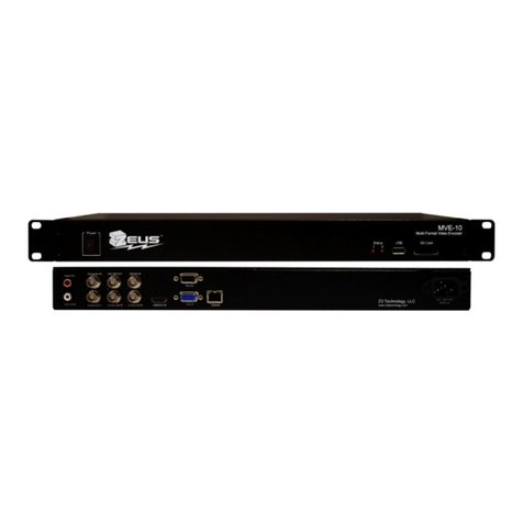
International Datacasting P56 Series User manual

1
P56x Manual 14032011

2
P56x Manual 14032011
Manual for P56x

3
P56x Manual 14032011
P56x Contact Information
International Datacasting Corporation Europe
Address : Marga Klompélaan 18
6836 BH ARNHEM
The Netherlands
Telephone : +31 26 323 6969
Fax : +31 26 323 3952
Web site : http://www.datacast.com

4
P56x Manual 14032011
P56x Contact Information.......................................................................................................... 3
Safety Information..................................................................................................................... 8
Conformity ................................................................................................................................ 9
1. Introduction ..................................................................................................................... 10
1.1. General functionality ................................................................................................. 10
1.2. Scope of Delivery...................................................................................................... 10
2. First Start ......................................................................................................................... 11
2.1. Before Start ............................................................................................................... 11
2.2. Back Panel Views...................................................................................................... 11
2.2.1. Encoder P561 ..................................................................................................... 11
2.2.2. Decoder P562..................................................................................................... 12
2.2.3. Codec P560 ........................................................................................................ 12
2.3. Installation for P56x models ...................................................................................... 12
2.4. LEDs......................................................................................................................... 14
2.5. Front panel keyboard ................................................................................................. 15
2.6. Front Panel Display ................................................................................................... 16
2.7. Default IP settings ..................................................................................................... 18
3. On System HTTP/Web-server .......................................................................................... 19
3.1. Navigation menu ....................................................................................................... 20
3.2. Status menu ............................................................................................................... 21
3.2.1. Codec ................................................................................................................. 21
3.2.2. Network ............................................................................................................. 22
3.2.3. Revisions............................................................................................................ 22
3.2.4. System Health .................................................................................................... 22
3.3. Configuration menu................................................................................................... 22
3.3.1. Codec ................................................................................................................. 23
3.3.2. Network ............................................................................................................. 23
3.3.3. ISDN (ISDN models only) ................................................................................. 24
3.3.3.1. ISDN Settings ............................................................................................. 24

5
P56x Manual 14032011
3.3.3.2. ISDN Status ................................................................................................ 24
3.3.4. SNMP ................................................................................................................ 24
3.3.4.1. SNMP Settings ............................................................................................ 25
3.3.4.2. SNMP Traps ................................................................................................ 25
3.3.5. Security .............................................................................................................. 25
3.3.6. Alarms................................................................................................................ 26
3.3.7. Date & Time....................................................................................................... 26
3.3.8. Profiles............................................................................................................... 26
3.4. Firmware Upload menu ............................................................................................. 27
3.5. Restart menu ............................................................................................................. 27
3.5.1. Restart ................................................................................................................ 27
3.5.2. Hard Reboot ....................................................................................................... 28
3.5.3. Hard Reboot with Defaults ................................................................................. 28
4. System Configuration ...................................................................................................... 29
4.1. Network address configuration at the unit.................................................................. 29
4.2. Network configuration using the Web Interface ......................................................... 31
4.3. P56x configuration using the Web Interface............................................................... 32
4.4. P560 Codec Configuration......................................................................................... 32
4.4.1. Sample Rate ....................................................................................................... 33
4.4.2. Encoder Channels............................................................................................... 33
4.4.2.1. Audio input ................................................................................................. 33
4.4.2.2. Analog level offset[dB] ............................................................................... 33
4.4.2.3. Encoding algorithm ..................................................................................... 33
4.4.2.4. Channel mode (Layer II) ............................................................................. 34
4.4.2.5. Channel mode (AAC LC) ............................................................................ 34
4.4.2.6. Channel mode (HE-AACv1)........................................................................ 34
4.4.2.7. Channel mode (HE-AACv2)........................................................................ 34
4.4.2.8. Channel mode (Lin PCM)........................................................................... 34
4.4.2.9. Linear PCM format ..................................................................................... 35
4.4.2.10. Bitrate ......................................................................................................... 35
4.4.2.11. UDP Destinations (Elementary Stream)....................................................... 35
4.4.3. Encoder MPEG-TS (DVB) ................................................................................. 35
4.4.4. Encoder Data Output .......................................................................................... 35
4.4.5. Decoder Data Source .......................................................................................... 35
4.4.6. Decoder Channels............................................................................................... 36
4.4.6.1. Audio output ............................................................................................... 36

6
P56x Manual 14032011
4.4.6.2. Output buffer[msec] .................................................................................... 36
4.4.6.3. Analog level offset[dB] ............................................................................... 36
4.4.7. Ancillary Data .................................................................................................... 36
4.4.7.1. Transport mode ........................................................................................... 36
4.4.7.2. RS232 baud rate .......................................................................................... 36
4.5. P561 Encoder Configuration...................................................................................... 36
4.5.1. Sample Rate ....................................................................................................... 37
4.5.2. Encoder Channels............................................................................................... 37
4.5.2.1. Audio input ................................................................................................. 37
4.5.2.2. Analog level offset[dB] ............................................................................... 37
4.5.2.3. Encoding algorithm ..................................................................................... 37
4.5.2.4. Channel mode (Layer II) ............................................................................. 38
4.5.2.5. Channel mode (AAC LC) ............................................................................ 38
4.5.2.6. Channel mode (HE-AACv1)........................................................................ 38
4.5.2.7. Channel mode (HE-AACv2)........................................................................ 38
4.5.2.8. Bitrate ......................................................................................................... 38
4.5.2.9. DVB specific settings .................................................................................. 38
4.5.3. Encoder MPEG-TS (DVB) ................................................................................. 39
4.5.3.1. DVB table selection..................................................................................... 39
4.5.3.2. Transport stream bitrate (bits/sec)................................................................ 39
4.5.3.3. DVB specific settings .................................................................................. 39
4.5.4. Encoder Data Output .......................................................................................... 39
4.5.4.1. Output mode................................................................................................ 39
4.5.4.2. UDP destination IP ...................................................................................... 40
4.5.4.3. UDP destination port ................................................................................... 40
4.5.5. Ancillary Data .................................................................................................... 40
4.5.5.1. Transport mode ........................................................................................... 40
4.5.5.2. RS232 baud rate .......................................................................................... 40
4.6. P562 Decoder Configuration ..................................................................................... 40
4.6.1. Decoder Data Source .......................................................................................... 40
4.6.2. Decoder Channels............................................................................................... 41
4.6.2.1. Audio output ............................................................................................... 41
4.6.2.2. Output buffer[msec] .................................................................................... 41
4.6.2.3. Analog level offset[dB] ............................................................................... 41
4.6.3. Ancillary Data .................................................................................................... 41
4.6.3.1. Transport mode ........................................................................................... 41

7
P56x Manual 14032011
4.6.3.2. RS232 baud rate .......................................................................................... 41
4.7. P56x Configuration using SNMP............................................................................... 41
5. System Update................................................................................................................. 42
6. Reset to Factory Defaults ................................................................................................. 43
6.1. Via front panel keyboard............................................................................................ 43
6.2. Via web interface....................................................................................................... 43
7. Error handling.................................................................................................................. 44
8. Technical specifications ................................................................................................... 45
8.1. Models ...................................................................................................................... 45
8.2. General Technical Data.............................................................................................. 46
8.3. Supported bit rates..................................................................................................... 46
8.3.1. Supported bit rates MPEG-1 Layer 2 .................................................................. 46
8.3.2. Supported bit rates AAC..................................................................................... 47
8.4. Connectors: ............................................................................................................... 47
8.4.1. Audio Analog In (LEFT / RIGHT)...................................................................... 48
8.4.2. Audio Analog Out (LEFT / RIGHT) ................................................................... 48
8.4.3. Audio Digital (AES / EBU) ................................................................................ 48
8.4.4. Ethernet 10 / 100 CTRL / DATA......................................................................... 49
8.4.5. Layout ANCILLARY DATA connector .............................................................. 49
8.4.6. Layout GPIO connector...................................................................................... 50

Safety Information
Electrical Safety
To prevent electric shock or hazard, do not attempt to disassemble
the unit.
Operation Safety
Avoid dust, humidity and temperature extremes. Do not place
product in any area where it may become wet.
Place the unit in a horizontal position and do not place anything
heavy on it.
Before using the product, make sure all cables are correctly
connected and the power cable is not damaged.
If you encounter te
qualified service technician or our
gevonden..
This symbol of the crossed out wheeled bin indicates that the product
(electrical and electronic equipment)
municipal waste. Check local regulations for disposal of electronic
products.
Electrical Safety
To prevent electric shock or hazard, do not attempt to disassemble
Operation Safety
Avoid dust, humidity and temperature extremes. Do not place
product in any area where it may become wet.
Place the unit in a horizontal position and do not place anything
Before using the product, make sure all cables are correctly
connected and the power cable is not damaged.
If you encounter te
chnical problems with the product, contact a
qualified service technician or our
Fout! Verwijzingsbron niet
This symbol of the crossed out wheeled bin indicates that the product
(electrical and electronic equipment)
should not be placed in
municipal waste. Check local regulations for disposal of electronic
8
To prevent electric shock or hazard, do not attempt to disassemble
Avoid dust, humidity and temperature extremes. Do not place
the
Place the unit in a horizontal position and do not place anything
Before using the product, make sure all cables are correctly
chnical problems with the product, contact a
Fout! Verwijzingsbron niet
This symbol of the crossed out wheeled bin indicates that the product
should not be placed in
municipal waste. Check local regulations for disposal of electronic

Conformity
The product complies with all the relevant safety requirements of the
appropriated directives.
RoHS:
The product complies with the
2002/95/EC.
EMV:
The product conforms to the following EU directives:
2006/95/EC Low Voltage Directive
2004/108/ EC EMC Directive
The product complies with all the relevant safety requirements of the
appropriated directives.
The product complies with the
Conformity as defined by the guideline
2002/95/EC.
The product conforms to the following EU directives:
2006/95/EC Low Voltage Directive
2004/108/ EC EMC Directive
9
The product complies with all the relevant safety requirements of the
Conformity as defined by the guideline

10
1. Introduction
1.1. General functionality
The P56x series is an Audio Encoder/Decoder/Codec for up to 8 stereo channels
(encoder channels, decoder channels or mixed). It is delivered in a 19'' 1U housing.
The connection depends on the configuration of the ordered device.
1.2. Scope of Delivery
The delivery contains:
•Unit
•Power Connector
•User Manual

2. First Start
2.1. Before Start
Check if scope of delivery (see section
the included packing list.
Installation in rack
When installing the
should make sure that the housing has the necessary air exchange
and if one P56x
Series mounted on top of the other you should have
a cooling system that produces an air current to prevent heat
accumulation.
Avoid dust, humidity, and temperature extremes. Do not place the
product in any area where it may become wet.
2.2. Back Panel Views
2.2.1. Encoder P561
Check if scope of delivery (see section
Scope of Delivery
) is complete with
When installing the
P56x
Series in a rack or another assembly you
should make sure that the housing has the necessary air exchange
Series mounted on top of the other you should have
a cooling system that produces an air current to prevent heat
Avoid dust, humidity, and temperature extremes. Do not place the
product in any area where it may become wet.
11
) is complete with
help of
Series in a rack or another assembly you
should make sure that the housing has the necessary air exchange
Series mounted on top of the other you should have
Avoid dust, humidity, and temperature extremes. Do not place the

2.2.2. Decoder P562
2.2.3. Codec P560
2.3. Installation for P56x
models
Mount the rack-
mount 19” 1U unit and connect the
1. Audio Connectors LEFT 1
-
Please connect an analog stereo input signal to any two of the
connectors.
In case of a digital input signal, please connect the digital stereo input
signal to any LEFT con
nector. The inputs can be configured to be analog or digital.
F
or configuration of “audio input” refer to sections 4.4
P561 Encoder Configuration
and 4.6
Up to 8 audio connectors can be either assigned to analog or digital input and output
signals in variable combinations.
Following configurations are available:
models
mount 19” 1U unit and connect the
following connectors:
-
4/ RIGHT 1-4, AES/EBU
Please connect an analog stereo input signal to any two of the
LEFT and RIGHT
In case of a digital input signal, please connect the digital stereo input
nector. The inputs can be configured to be analog or digital.
or configuration of “audio input” refer to sections 4.4
P
560 Codec Configuration
and 4.6
P562 Decoder Configuration.
Up to 8 audio connectors can be either assigned to analog or digital input and output
signals in variable combinations.
Following configurations are available:
12
LEFT and RIGHT
In case of a digital input signal, please connect the digital stereo input
nector. The inputs can be configured to be analog or digital.
560 Codec Configuration
, 4.5
Up to 8 audio connectors can be either assigned to analog or digital input and output

13
•Encoder: up to 4 analog inputs or up to 8 digital AES/EBU inputs or mixed
•Decoder: up to 4 analog outputs or up to 8 digital AES/EBU outputs or mixed
•Codec: up to 2 analog inputs or 4 digital AES/EBU inputs or mixed and up to 2
analog outputs or 4 digital AES/EBU outputs or mixed
Depending on the way the unit was ordered, the analog connectors have to be
connected to the correct LEFT and RIGHT inputs.
2. Ethernet ports
•ETHERNET 10/100 CTRL
Please connect the network to the LAN interface connector ETHERNET 10/100
CTRL, for the controlling of the device.
•ETHERNET 10/100 DATA (Models without ISDN operation only)
Then connect the data network to the LAN interface connector ETHERNET 10/100
DATA, for the transport stream output over IP.
3. ASI connectors
ASI 1 or ASI 2
Please connect the ASI cable to ASI 1 or ASI 2 for transport stream output.
4. ISDN (Advanced ISDN models only)
Please connect the rightmost Audio connector to the ISDN connector.
5. GPIO
Please connect the GPIO Connector to the control device.
6. ANCILLARY DATA
Output signal e.g. RDS
7. Option 1 ( future option )
8. Option 2 ( future option )
9. A/C power
There are two possible device variants:
a) One A/C power connector and switch.
Plug in the A/C power connector and switch on the unit.
b) Two A/C power connectors for redundant unit.
Plug in the A/C power connector.

2.4. LEDs
Status LEDs
1. Power
The unit has AC power.
2. RUN
The unit has successfully completed its boot cycle and is running.
3. STATUS 1
The unit is running and streaming data.
4. STATUS 2
STATUS 2 lights up if a valid AES signal has been detected at the digital audio input
otherwise no
AES signal (LED off) has been detected at the digital audio input and
the unit has switched to the
analog
updated approximately every 500msec.
5. ERROR
An error has occurred and the
P56x
The unit has successfully completed its boot cycle and is running.
The unit is running and streaming data.
STATUS 2 lights up if a valid AES signal has been detected at the digital audio input
AES signal (LED off) has been detected at the digital audio input and
analog
input connectors. The AES-
signal state is
updated approximately every 500msec.
P56x
has stopped processing.
14
STATUS 2 lights up if a valid AES signal has been detected at the digital audio input
AES signal (LED off) has been detected at the digital audio input and
signal state is

2.5. Front panel keyboard
With the front panel keyboard you can configure and display the status of the
Buttons
Generally there are three kinds of buttons:
•Cursor buttons
•ESC button
•ENTER button
1. Cursor buttons
The cursor buttons enable all
navigations through the menus and switch between
different screens.
2. ESC button
The ESC button always leads to the next exit. Pressing ESC several times
eventually leads back to the status screen.
3. ENTER button (top right)
This button leads into a menu to ma
made, by pressing it on the “save” field.
With the front panel keyboard you can configure and display the status of the
Generally there are three kinds of buttons:
navigations through the menus and switch between
The ESC button always leads to the next exit. Pressing ESC several times
eventually leads back to the status screen.
This button leads into a menu to ma
ke modifications and confirms any changes
made, by pressing it on the “save” field.
15
With the front panel keyboard you can configure and display the status of the
P56x.
navigations through the menus and switch between
ke modifications and confirms any changes

2.6. Front Panel Display
After switching-
on the unit, the Qbit logo appears for a short time before the status
screen is shown on the display.
After the boot process, the
unit is running the last saved configuration. In case the
unit is powered up the first time, it is running the factory configuration. You need to
set up the IP address for configuration. See section 4.1
configuration at the unit
and 4.2
Process:
displays the function (Encoder, Decoder, Codec
Codec-
Decoder) and the state;
Blinking “** Running**” means no failure, otherwise the a
failure is displayed.
Input:
displays the channel number and the configuration of the audio input
(analog or digital)
Codec:
displays the stream
Output:
displays the audio output
Pressing the ENTER button leads you to the Main screen. In this
can select the following options:
•Network (CTRL)
•
Network (DATA) (N/A for ISDN models)
In the Main menu area the navigation is possible with the
and the system settings can be configured by selecting the highlighted
Pressing the ENTER button on the highlighted option leads you to the menu DATA or
CTRL for editing the system settings.
address fields is done by using the
into one of the address fields and back, ESC always leads to the next exit and
on the unit, the Qbit logo appears for a short time before the status
unit is running the last saved configuration. In case the
unit is powered up the first time, it is running the factory configuration. You need to
set up the IP address for configuration. See section 4.1
Network address
and 4.2
Network configuration using the Web Interface
displays the function (Encoder, Decoder, Codec
-Encoder or
Decoder) and the state;
Blinking “** Running**” means no failure, otherwise the a
ppropriate
failure is displayed.
displays the channel number and the configuration of the audio input
displays the stream
displays the audio output
Pressing the ENTER button leads you to the Main screen. In this
screen the user
can select the following options:
Network (DATA) (N/A for ISDN models)
In the Main menu area the navigation is possible with the
and
cursor buttons
and the system settings can be configured by selecting the highlighted
option.
Pressing the ENTER button on the highlighted option leads you to the menu DATA or
CTRL for editing the system settings.
Navigating through the screen and inside the
address fields is done by using the
or
and
or
cursor buttons. ENTER leads
into one of the address fields and back, ESC always leads to the next exit and
16
on the unit, the Qbit logo appears for a short time before the status
unit is running the last saved configuration. In case the
unit is powered up the first time, it is running the factory configuration. You need to
Network configuration using the Web Interface
.
ppropriate
displays the channel number and the configuration of the audio input
screen the user
cursor buttons
option.
Pressing the ENTER button on the highlighted option leads you to the menu DATA or
Navigating through the screen and inside the
cursor buttons. ENTER leads
into one of the address fields and back, ESC always leads to the next exit and

discards any changes made. Pressing ESC several times eventually leads back to
the status screen. To confirm any changes made, the ENTER button has to be
pressed on the “save” field.
For configuration refer to sections 4.4
Configurationor 4.6 P
562 Decoder
There are two channel level meter screens to check
channels.
Escape to the channel screen can be done by pressing the
Pressing the
or
button several times changes between
channel level meter screen, horizontal or vertical.
There are two diagrams, one for each channel as a horizontal
overview of all implemented audio channels as a vertical
Channel screen: horizontal-bar
chart
Channel screen: vertical-bar
chart
If you have more than one implement
audio
channel screens by using the
The channel screen can only be requested but not changed.
For P560 Codec only:
Within the status screen you can switch between the encoder status scree
decoder status screen by pressing the
discards any changes made. Pressing ESC several times eventually leads back to
the status screen. To confirm any changes made, the ENTER button has to be
For configuration refer to sections 4.4
P560 Codec Configuration, 4.5 P
561 Encoder
562 Decoder
Configuration.
There are two channel level meter screens to check
the activity of the used audio
Escape to the channel screen can be done by pressing the
or
button several times changes between
status screen,
channel level meter screen, horizontal or vertical.
There are two diagrams, one for each channel as a horizontal
-bar
chart, and an
overview of all implemented audio channels as a vertical
-bar chart.
chart
chart
If you have more than one implement
ed audio
channel you can choose the different
channel screens by using the
and
cursor buttons.
The channel screen can only be requested but not changed.
Within the status screen you can switch between the encoder status scree
n and the
decoder status screen by pressing the
and
cursor buttons.
17
discards any changes made. Pressing ESC several times eventually leads back to
the status screen. To confirm any changes made, the ENTER button has to be
561 Encoder
the activity of the used audio
button.
status screen,
chart, and an
channel you can choose the different
n and the

18
2.7. Default IP settings
By default the unit has got the following IP settings:
Address: 192.168.093.151
Netmask: 255.255.255.000
Gateway: 000.000.000.000

3.
On System HTTP/Web
It is not recommended to use the web interface for the configuration of the
unit´s IP addresses. If you forget the actual IP address, the device
become unreachable via IP.
The P56x
provides an integrated web
the unit is reachable via IP. Refer to section 4.1
unit
for information how to set the IP address via front panel display.
Open your web browser and type in the IP address of the unit to be changed. The
P56x homepage and a pop-
up window appears which asks for the required
authentication.
Type the user name and password in and confirm with the OK button.
On System HTTP/Web
-server
It is not recommended to use the web interface for the configuration of the
unit´s IP addresses. If you forget the actual IP address, the device
become unreachable via IP.
provides an integrated web
-
server, so you can access them as soon as
the unit is reachable via IP. Refer to section 4.1
Network address configuration at the
for information how to set the IP address via front panel display.
Open your web browser and type in the IP address of the unit to be changed. The
up window appears which asks for the required
Type the user name and password in and confirm with the OK button.
19
It is not recommended to use the web interface for the configuration of the
unit´s IP addresses. If you forget the actual IP address, the device
may
server, so you can access them as soon as
Network address configuration at the
Open your web browser and type in the IP address of the unit to be changed. The
up window appears which asks for the required

20
Shut down the browser to log off the P56x web-server.
3.1. Navigation menu
The navigation menu supports the following:
•Display the system status
•Configuration of the network and P56x
•Upload of a new firmware version
•Restart of the system after new configuration or firmware upload
Menu items are:
•Home
•Status
•Configuration
•Firmware Upload
•Restart
After a few seconds of inactivity, the P56x homepage leads you always to the
Status menu screen. This menu gives you an overview of the general system status
according to the model.
Note:
Default username: q56xadmin
Default password: qbit
Username and password are case sensitive
This manual suits for next models
2
Table of contents
Popular Media Converter manuals by other brands

Keysight Technologies
Keysight Technologies 11667C Operating and service manual

ZeeVee
ZeeVee ZvPro 250 Get going guide

Badger Meter
Badger Meter Blancett B220-885 user manual

Siemens
Siemens Synco 200 SEZ220 Documentation on basics

MSB Technology
MSB Technology The Select DAC user guide

Optoma
Optoma ThemeScene HD3000 user guide