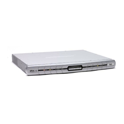
International Datacasting STAR Generation 2 User manual

STAR Receiver
Generation 2
For Audio Networks
User’s Guide
Revision 1.4

S T A R G e n 2 R e c e i v e r U s e r ’ s G u i d e
Page 2 of 47
Table of Contents
SAFETY WARNINGS................................................................................................................................4
GETTING STARTED .................................................................................................................................5
Models..................................................................................................................................................5
How to Use This Guide ........................................................................................................................5
QUICK START...........................................................................................................................................5
What You Should Have Received........................................................................................................5
The Front Panel....................................................................................................................................6
The Rear Panels –STAR-Four & STAR-Two......................................................................................7
Default Settings....................................................................................................................................7
First Installation and Configuration of the STAR...............................................................................7
USER INTERFACE....................................................................................................................................9
Remote Control with a WEB Browser ..................................................................................................9
The Menu Bar.......................................................................................................................................9
Identity....................................................................................................................................................9
Input......................................................................................................................................................10
SAT-IN.............................................................................................................................................10
IP-IN.................................................................................................................................................11
DVB-TS.................................................................................................................................................12
Decoder................................................................................................................................................13
Decoder Audio.................................................................................................................................13
Decoder Backup Channel x.............................................................................................................14
Decoder Data ..................................................................................................................................15
Output...................................................................................................................................................15
Control..................................................................................................................................................16
Control MGMT IP.............................................................................................................................16
Control MGMT Notification Mode....................................................................................................17
Control MGMT Notification Priority..................................................................................................18
Control MGMT Notification Destination...........................................................................................18
Control I/O .......................................................................................................................................18
Control ACMM.................................................................................................................................18
Alarm ....................................................................................................................................................19
Alarm Menus and Sub Menus.........................................................................................................20
Status ...................................................................................................................................................21
Utility ....................................................................................................................................................25
Logout ..................................................................................................................................................28
ADVANCED TOPICS ..............................................................................................................................29
Using your PMR...................................................................................................................................29
Time Shifting.......................................................................................................................................29
Using Date and Time..........................................................................................................................30
Recording and Playback Reports.......................................................................................................31
GUI TIPS..................................................................................................................................................32
Drop down Menus ..............................................................................................................................32
Valid numeric Ranges ........................................................................................................................32
Text in Red.........................................................................................................................................32
FAQ’S ......................................................................................................................................................33
Why are there periods of silence in my playback?.............................................................................33
If a reboot occurs during playback what happens to the playback? ..................................................33

S T A R G e n 2 R e c e i v e r U s e r ’ s G u i d e
Page 3 of 47
Why can I not always edit active time shift recording or playbacks? .................................................33
I changed my SD card; do I lose all the recording and playback schedules?....................................33
How many recordings can I store?.....................................................................................................33
Can I take information off the receiver? .............................................................................................33
If a playback is interrupted, what will happen?...................................................................................33
How many playbacks can I add to a scheduled event?.....................................................................34
How long does the recording and playback information stay on the receiver?..................................34
What happens to recordings over Daylight Savings Time changes and on a leap year?..................34
The Warning LED is illuminated, what does this mean?....................................................................34
The Alarm LED is showing, what does this mean?............................................................................34
REMOTE CONTROL BY SNMP..............................................................................................................36
CONNECTOR SPECIFICATIONS...........................................................................................................37
KEYPAD CONTROL ...............................................................................................................................38
Measurement Displays.......................................................................................................................38
Settings Menu Flowchart....................................................................................................................39
WEEE DISPOSAL INSTRUCTIONS.......................................................................................................45
WARRANTY & SERVICE INFORMATION.............................................................................................45

S T A R G e n 2 R e c e i v e r U s e r ’ s G u i d e
Page 4 of 47
Safety Warnings
THE UNIT MUST BE INSTALLED BY A QUALIFIED SERVICE PERSON AND THE EXTERNAL
EARTH CONNECTION MUST BE MADE BEFORE CONNECTING THE AC SUPPLY.USE A
GROUNDED POWER OUTLET ONLY.
AN ANTI-SHOCK DEVICE MUST BE INSTALLED ON THE ANTENNA CABLE CONNECTING TO
THE UNIT.
THE UNIT MUST BE GROUNDED AT THE REAR PANEL GROUND CONNECTION.
DO NOT OPERATE THE UNIT IN DIRECT SUNLIGHT,ADUSTY OR DAMP ENVIRONMENT AND
DO NOT BLOCK THE VENTILATION HOLES.THE UNIT IS DESIGNED TO OPERATE IN A
TEMPERATURE RANGE OF 0ºC TO 40ºC.THE POWER RATING AND HEAT GENERATION OF
THE UNIT ARE SUCH THAT IT CAN BE PLACED IN A 19” CABINET WITHOUT SPECIAL
COOLING FACILITIES.HOWEVER,SUFFICIENT CLEARANCE MUST BE MAINTAINED
BETWEEN THE UNIT AND OTHER EQUIPMENT (A 1RU GAP).
DO NOT OPEN THE UNIT FOR ANY REASON.THIS IS DANGEROUS AND MAY VOID YOUR
WARRANTY.
IF THE UNIT FAILS TO OPERATE CALL YOUR SERVICE PROVIDER CUSTOMER SUPPORT.
THE STAR IS A 19” 1U RACK-MOUNTING UNIT WITH CONNECTOR ACCESS AT THE
REAR.THE UNIT CAN BE MOUNTED AT THE FRONT OF A 19”RACK USING AN
APPROPRIATE MOUNTING SET.HOWEVER,THE USE OF LATERAL SUPPORT IS
STRONGLY RECOMMENDED.

S T A R G e n 2 R e c e i v e r U s e r ’ s G u i d e
Page 5 of 47
Getting Started
International Datacasting Corporation (IDC) would like to thank you for purchasing this STAR Generation 2
receiver (herein referred to as the “receiver”). This User’s Guide provides step by step instructions on how to
connect the receiver, access satellite services, and set system and audio output configurations.
Models
Your STAR Generation 2 receiver is one of a familyof STAR receivers. A datasheet at the end of this document
provides the Technical Specifications of your STAR receiver. Readers of this manual who use a STAR-Two
receiver should ignore any references to audio 3 & 4, decoder 3 & 4 or channel 3 & 4.
How to Use This Guide
This guide describes the operation of your receiver through the GUI and through the keypad interface. Within
the document you will find:
oa Quick Start section about connecting to the receiver and what the displays mean.
oa User Interface section explaining how to use the GUI interface to configure the receiver and
enable the outputs.
oan Advanced Topics section on how to use the Professional Media Recorder (if installed).
oa GUI Tips section explaining extra information and on-screen choices.
oa FAQ section.
oa Keypad Control section for local control of your receiver.
Quick Start
If you have installed IDCproducts before, youcan skip this section. If not, you will be familiarized with the status
and controls of the STAR receiver prior to being shown how to find the receivers IP Address and how to connect
to it through the GUI to configure the receiver for use.
What You Should Have Received
You should have received the following package:
oOne (1) STAR- Generation 2 Receiver;
oOne (1) power cord, suitable for use in your country;
oOne (1) copy of this User’s Guide – also available online from the IDC CustomerService FTP site.
You will need audio cables to connect the receiver to your system. Please keep one set of packaging that your
receiver came in, to allow for a safe return for repair if required.

S T A R G e n 2 R e c e i v e r U s e r ’ s G u i d e
Page 6 of 47
The Front Panel
The STAR front panel contains nine LED indicators, a headphones jack and a keypad LCD combination.
[1] Headphones
[2] Status information: STAR-Four STAR-Two
The status information of the receiver is shown in the LEDs as described in the table below. A blank cell shows
an unused status/colour combination.
[3] LCD
The LCD display is used to view receiver status, view receiver configurations and/or set receiver configurations.
How to access these settings is described in the section Keypad Control.
[4] Keyboard
LED status indication
Indication
OFF
GREEN / Flashing Green
RED
YELLOW
LOCK
Unit disconnected
or power failure
Locked to carrier
Not locked to carrier
WARNING
No warning
Warning
ALARM
No alarm
Alarm
AUDIO 1/2
No service
Audio OK / Playing local file
PID/MPE-IP or audio error
REMOTE
No M & C link
Link connected remotely
Local control; link available
AUDIO 3/4
No service
Audio OK / Playing local file
PID/MPE-IP or audio error
OPTION
Future Use
RECORD
Recording
/ Recording programming
1
2
3
4
Scroll buttons (4)
Select button
Cancel button

S T A R G e n 2 R e c e i v e r U s e r ’ s G u i d e
Page 7 of 47
The Rear Panels – STAR-Four & STAR-Two
[1] Grounding
[2] Mains AC 100-240v built in fuse 2.5A
[3] Alarm contacts (3)
[4] Audio In (Future use)
[5] Audio Channels & Relays 1, 2, 3 & 4
[6] ASI In or ASI Out [Factory installed option]
[7] Data LAN
[8] RS232 Comm port
[9] Monitor & Control LAN
[10] L-band input and loopthrough
[11] SD card slot
[12] Recovery reset
Default Settings
Your STAR receiver is supplied with these default settings:
1. Control mode is: remote
2. IP mode is: DHCP
First Installation and Configuration of the STAR
1. Connect power to the power inlet without connecting the L-band cable to your STAR receiver. The front
panel LCD will show “Star Four G2 Booting OS”. The LEDs on the front panel show (on the left):
2. After a few seconds all LEDs flash once and the LCD screen will display “Initializing”. When initialization
is complete after a few seconds, the LEDs show (on the right), with no external connections:
1
3
5A
5C
7
9
10
12
11
8
4
2
5B
5D
6

S T A R G e n 2 R e c e i v e r U s e r ’ s G u i d e
Page 8 of 47
INDICATIONS
COLOR
LOCK
NONE
WARNING
YELLOW
ALARM
RED
AUDIO 1
NONE
AUDIO 2
NONE
REMOTE
NONE
AUDIO 3 /OPTION 1
NONE
NONE
AUDIO 4 /OPTION 2
NONE
NONE
RECORD
NONE
INDICATIONS
COLOR
LOCK
RED
WARNING
RED
ALARM
RED
AUDIO 1
RED
AUDIO 2
RED
REMOTE
NONE
AUDIO 3 /OPTION 1
RED
NONE
AUDIO 4 /OPTION 2
RED
NONE
RECORD
NONE
3. Connect the STAR to a DHCP IP network. If a DHCP network is not available you can use the LCD to
configure a static IP address (Control>MGMT> IP Static Address). The STAR default is 192.168.0.1. Then
connect the STAR with a switch or computer; and set your computer IP address in the same range.
4. Connect a personal computer to the receiver, open a web browser and connect to the receiver by typing the
IPaddress of the receiver in your browsers address bar.
5. Login with: Username: admin. Password: 12345. You can change the login username and password
with the web GUI in the “CONTROL>MGMT>IP” menu under “Web”.
Your STAR receiver is nowready for use.
Note: On subsequent startup of the STAR receiver a comprehensive check of the SD card structure and content
takes place. This can delay the appearance of Trigger information on the Utility Trigger page by up to 20
seconds.

S T A R G e n 2 R e c e i v e r U s e r ’ s G u i d e
Page 9 of 47
User Interface
The receiver can be configured through the Graphical User Interface or from the front panel Keypad.
Remote Control with a WEB Browser
When you have logged in, you will see the Web Configuration Manager page.
The Menu Bar
There are 8 top level menus and a logout button in the menu bar presented here in order left to right.
Identity
In the Identitypage you can fill in specific information that will be visible on the Welcome page and you can also
include a link that points to a manual.
Device name, Device type,
Serial number, Firmware
version and activated Options.
Menu bar (see below for details).
Follow the Link to an online
Manual. Define the link in the
“IDENTITY” menu. See next page.
Monitoring Status & Routing.
Warning & alarms indicator.
Log and Syslog viewing links.
Time, Date& Synchronization
with SNTP server.

S T A R G e n 2 R e c e i v e r U s e r ’ s G u i d e
Page 10 of 47
DEVICE NAME, DEVICE LOCATION, DEVICE CONTACT, and DEVICE INFO 1-12: enter additional
information which will be visible at the WELCOME page of the WEB GUI. This information can be a link to
another website.
DEVICE MANUAL LINK: this link to a server can be defined to point to a manual. The link button MANUAL will
be found on the menu bar when a link is defined. Link Examples are: file://///server/share/path, ftp://server/file,
ftps://server/file, http://sitelink, https://sitelink.
Input
There are 2 input sources: SAT-IN (which is a satellite L-Band signal) and IP-IN (a Transport Stream over IP
input). A factory installed optional ASI input is also available, and is set up under Menu: DVB-TS> INPUT.
SAT-IN
Different types of outdoor LNBs are supported. For easy setup, the Local Oscillator (LO) frequency can be
entered. However, when the STAR receiver is used with Netmanager control the LO frequency needs to be set
to 0 KHz, and all receiver frequencies need to be entered in the L-band range only.
NCC = Network Control Channel, which contains the network control data generated by IDC’s Netmanager2.
Polarization in the Carrier definition menu’s are only available when the LNB mode is set to “Universal”.
The preferred carrier setting is useful when a transition to a carrier is needed. This function is also supported
and controlled by NCC. If only one Carrier setting is required the Prefered can be set to “Carrier A (or B) only.

S T A R G e n 2 R e c e i v e r U s e r ’ s G u i d e
Page 11 of 47
The options to set the other carrier will be removed from the receivers interface when “Carrier A (or B) only” is
selected. This feature is not controlled by NCC.
The 12 digit BISS session keys A and B are normally provided from the head end. They can be entered here
and show as “- - - - “ when not present and “ * * * *” when present.
IP-IN
LOCAL PORT Mode: Select between AUTO (up to 1Gbit) or 100 Mbit (Half or Full duplex).
LOCAL PORT IP Address: This is the IP Address in the LAN network.

S T A R G e n 2 R e c e i v e r U s e r ’ s G u i d e
Page 12 of 47
INPUT STREAM IP Address/UDP Port: This is the IP Address/Port number on which the MPEG2 TSoverIP
stream is received.
DVB-TS
INPUT: Decoder input can be selected between SAT-IN (L-band tuner), IP-IN (TSoIP) or ASI-IN (As Factory
installed option only). .
PID LIST: This allows you to enter and enable the Network Time Protocol (NTP) PID, the Network Control
Channel (NCC) PID, the Electronic Channel Guide (ECG) PID and the FlexKey (ECM) PID if the option is
installed. MPE PIDs that are required to decode IP Audio services are automatically loaded to each decoder’s
PID list and are not shown here.
DVB-TS FLEXKEY: (Optional) This setting is needed to identify the IP address and port number which contains
the ECM messages sent by FlexkeyEncryptor. Requires ECM PID.

S T A R G e n 2 R e c e i v e r U s e r ’ s G u i d e
Page 13 of 47
Decoder
Decoder Audio
CHANNEL x Audio:
STREAM: when stream is set to MPE then select from:
MODE: OFF, CHAN.GUIDE, USER DEFINED, TONE.
Note: If Channel Guide mode is selected, the receiver will populate the service list automatically.
The channel information is provided by the SDP packets from the Event Managers at the head-
end. The MPE PID (ECG PID) for the SDP packets must be added to the receiver PID list to get
the list of Services. The Channel Guide is the list of programs you can select in MPE mode. The
user selects the wanted service, and the unit will select the appropriate IP address and PORT
number. In MPE mode this address and port has to be done manually.
Note: If tone is selected the receiver outputs a 1Khz note.
STREAM: when stream is set to PES then select from:
MODE: OFF, PSI, PID, TONE.
Note: In PSI mode the receiver will populate its service list from the PSI table in the DVB carrier.
The user selects the wanted service, and the unit will select the appropriate PID. In PID mode this
PID has to be set manually.
Note: If tone is selected the receiver outputs a 1Khz note.
SERVICE: shows the list of services available. When there is no list “SIGNAL?” will be shown.
15 kHz LOWPASS: ON/OFF. Enabling the low pass filter limits the upper frequency range to 15Khz
with a 3db/octave attenuation.
GAIN: Set the gain from -18 to +18 dB, in steps of 1 dB.
STEREO/MONO: Select Stereo (Dual), Mono L+R, Mono L, Mono R.
DELAY: Input presentation delay from 0 to 8000 milliseconds.

S T A R G e n 2 R e c e i v e r U s e r ’ s G u i d e
Page 14 of 47
OPTIONAL (not shown):
LIMITER ENABLED: ON/OFF.
LIMITER LEVEL: -50 to 0 dBFS, in steps of 1 dB.
LIMITER RECOVERY: 20 (Fast) to 100 (Slow) Milliseconds recovery time.
Decoder Backup Channel x
The backup for each audio channel can be enabled/disabled and the order of choice for the backup
source can be defined. Additionally each backup source can be viewed and or configured. As delivered
there are no audio backup files on the SD card. Multiple audio files (.mp2 or .mp3) can be stored in the
SD card root directory, but only one can be identified as the default file for each decoder. If the Service
Operator has delivered a backup playlist this will be played instead of the default file (If enabled). Consult
Service Operator for full details.
PRIORITY: Select the order of the available backup sources.
BACKUP PLAYLIST: Select the audio file from the SD card to be played as backup for this Decoder.
Note: If a Backup Playlist is available from the Head end it will be played instead. If the Backup
Playlist has any missing content, that content will be skipped over and the playlist will continue to
play (loop playback). If there is no Backup Playlist the receiver will go to the next priority Backup.
IP STREAM: Choose the SOURCE of the Backup audio from: INTERNET SERVICE; RTP/IP AUDIO or
MPEG TS OVER IP. Once selected the required SOURCE calls up the appropriate set of parameters to
specify the addressing.
Note: In INTERNET SERVICE source, Port Mapping uses the Service ID+10,000 as the port
number (User equipment configuration is required). User Defined allows the user to specify the
port number.
Note: In MPEG TS over IP, Auto in PID Mode uses as backup any PID in the IP-IN transport
stream that matches the current program. Manual allows the user to specify the PID played.

S T A R G e n 2 R e c e i v e r U s e r ’ s G u i d e
Page 15 of 47
Decoder Data
CHANNEL x Data:
STREAM: when stream = MPE (in menu DECODER>AUDIO) then:
MODE: OFF, ANC. DATA AUDIO CH1 (Data on Channel xA), ASYNC. DATA (Data on channel xB).
Note: ANC. DATA is data transport in the ancillary field of coded audio. ASYNC. DATA is data
transport in the MPE RTP header of audio stream.
STREAM: when stream = PES (in menu DECODER>AUDIO) then:
MODE: OFF, ANC. DATA (data on Channel xA), PRIV. DATA (data on Channel xB).
Note: ANC. DATA is data transport in the ancillary field of coded audio. PRIV. DATA is data
transport in a separate PID of the transport stream.
FORMAT: IRT, J.52.
Note: these formats for embedded Async data are only available if Device Special 2 is installed.
PROCESS: MUX, OFF.
BAUD: Output baud rate of the Anc/Async data: 1200, 2400, 4800, 9600, 19k2, 38k4, 57k6 baud.
Output
MODE: Auto (up to 1GB), 100Mb HD, 100Mb FD.
IP ADDRESS: The source address of the output stream.
OUTPUT STREAM: Enabled,
Note: In Disabled mode the (multicast) IP Address and UDP Port are not available.
Note: ASI-OUT is available only with Factory installed option: ASI-OUT.

S T A R G e n 2 R e c e i v e r U s e r ’ s G u i d e
Page 16 of 47
Control
Control MGMT IP
Choose the parameters to configure the network connections, utilize SNMP, specify the SNTP server, a
Syslog server, configure the web access and change the username/password combination.

S T A R G e n 2 R e c e i v e r U s e r ’ s G u i d e
Page 17 of 47
MODE: DCHP, MANUAL
Note: In DCHP mode Static Address, Subnet Mask and Gateway Address are not available. .
Control MGMT Notification Mode
Choose the parameter (ALL; HEARTBEAT; SETTING CHANGED; CONTROL MODE CHANGED;
CONTROL MODE LOCAL SUPPRESS) that produces a notification and the type of that notification (OFF;
WARNING; WARNING+ALARM) to the SNMP trap set under Control>MGMT>Notification>Destination.

S T A R G e n 2 R e c e i v e r U s e r ’ s G u i d e
Page 18 of 47
Control MGMT Notification Priority
Select the priority for the notifcation of an alarm in a parameter. Each parameter shown on the Control MGMT
Notification Mode Alarm Mode list can be assigned a priority between 1 and 4294967295 with 1 being the
highest priority. The default value is 0 and indicates No Priority
Control MGMT Notification Destination
Enable/Disable notifications to the chosen SNMP destinations.
Control I/O
This will allow operators to view and change the status of the contacts manually for testing. Please note that
Decoder Data Process needs to be switched to OFF. (Supportdepends on thedevice configuration).
Control ACMM
View and enter the Trigger PID parameters and the PID, IP address and corresponding port for each of
the XD packet streams received by your Star receiver. Do not change these parameters without
consulting your Service Operator.
ENABLE /DISABLE: Enable/Disable participation in network-wide trigger activation.
Note: Allow or prevent triggering of receiver by head end regardless of channel being played.
TRIGGER PID: PID containing trigger list.

S T A R G e n 2 R e c e i v e r U s e r ’ s G u i d e
Page 19 of 47
Alarm
The following settings are available in the ALARM submenus:
MODE : OFF = Warning and Alarm are switched off.
: Warning Only Upon an error condition the Warning light on the front
will be activated.
:Warning+RelayA Upon an error condition, after the warning delay period
has passed, the Warning light on the front panel will
illuminate. It will remain illuminated until the alarm delay
period has passed, at which point the Warning LED will
turn off, the Alarm Led will flash red and relay A will
become active.
: Warning+RelayB Upon an error condition, after the warning delay period
has passed, the Warning light on the front panel will
illuminate. It will remain illuminated until the alarm delay
period has passed, at which point the Warning LED will
turn off, the Alarm Led will flash red and relay B will
become active.
: Warning+RelayC Upon an error condition after the warning delay period
has passed, the Warning light on the front panel will
illuminate. It will remain illuminated until the alarm delay
period has passed, at which point the Warning LED will
turn off, the Alarm Led will flash red and relay C will
become active.

S T A R G e n 2 R e c e i v e r U s e r ’ s G u i d e
Page 20 of 47
LEVEL Not present for all parameters. When present it is
programmable between the limits revealed when you
hover your mouse over the Level field.
W- DELAY Delayin seconds before the warning light will be activated.
A- DELAY Delay in seconds before the alarm light and relay will be
activated.
Note: to receive an alarm on the relay outputs, the alarms must be properly configured.
1. Warning Delay (W-DELAY) is programmable between 0 and 599 seconds.
2. Alarm Delay(A-DELAY) is programmable between 1 and 600 seconds.
The warning-delayshould always be less than the alarm-delay. When a warning-delay is entered which is larger
than the alarm-delay, the alarm-delay will automatically be set to the warning-delay-time + 1 second.
It is good practice to disable Alarms for items that do not need to be monitored. For example, if you are using
IP- IN and are not connected to a Satellite feed, then disable the SAT- IN related alarms.
Alarm Menus and Sub Menus
Shows information about and allows setting of the alarms for input and audio levels including backup and
data. The alarm information can also be printed. Three sub-menus with multiple sub-menus contain the
information:
INPUT: the ASI- IN, SAT- IN or IP- IN parameters.
DECODER: the PSI, AUDIO, BACKUP and DATA parameters for all channels.
PMR: the Recording and Playback parameters for the PMR.
The Alarm mode contains multiple pull down menus for selection of the item tomonitor.
After selection, in the EDIT mode, each selected item (MODE, LEVEL, WARNING DELAY and ALARM
DELAY) can be independently set (see examples below). Hover over a field underlined “…………” to see the
valid range. Individually alarmed items (RF LOCK, POWER etc.,) on a page can be saved individually or the
page can be completed then saved.
Table of contents
Other International Datacasting Receiver manuals
