International Safety Instruments Surveyor Instructions for use
Copyright 2001 International Safety Instruments, Inc. 17
Owners Operation Manual
Thermal Imaging System
International Safety Instruments, Inc.
Copyright 2001
SURVEYOR

Copyright 2001 International Safety Instruments, Inc. 15
Owner’s Operation Manual
WARNING
Disassembly of the components beyond the procedures described
herein shall not be performed. Additional disassembly may cause
component damage and shall be performed only by authorized
personnel or ISI.
INTERNATIONAL SAFETY INSTRUMENTS, INC.
922 Hurricane Shoals Road Lawrenceville, GA 30043
770-962-2552 888-ISI-SAFE (toll free) FAX 770-963-2797
Part Number 084061 Issue A September 2001
Artwork Number A49089 Issue A September 2001
Thermal Imaging System
SURVEYOR

Copyright 2001 International Safety Instruments, Inc.
14
TABLE OF CONTENTS
Preface
Warnings and Exclusions 1
1.0 Specifications 3
2.0 System Components 4
3.0 General Operation 4
3.1 Battery Installation 4
3.2 Red Button Operation 5
3.3 Black Button Operation 5
3.3.1 Videomix
3.3.2 Reverse Polarity
3.4 Kevlar Handstrap 5
3.5 Kevlar Neckstrap 6
3.6 Battery Life Indicator 6
3.7 SensorTemperatureWarning 6
3.8 SettingTime & Date 7
3.9 SettingTemperature Scale 7
4.0 Options & Accessories 8
4.1 Pyrometer 8
4.2 Video Mix 8
4.3 Reverse Polarity 9
4.4 Pistol Grip Handle 9
4.5 Surveyor Transmitters 9
5.0 Inspection and Maintenance 10
5.1 General Inspection After Each Use 10
5.2 Periodic Inspection 11
5.3 Battery Maintenance 11
5.4 Cleaning 12
6.0 Warranty 13

Copyright 2001 International Safety Instruments, Inc. 1
PREFACE
______________________________________________________________________________________
IMPORTANT POINTS - PLEASE READ CAREFULLY
THE ISI SURVEYOR THERMAL IMAGING SYSTEM IS NOT LIFE
SUPPORT EQUIPMENT AND SHOULD NOT BE USED AS SUCH.
FAILURETO PROPERLY MAINTAIN AND OPERATETHIS PROD-
UCT COULD RESULT IN ITS’FAILURE LEADINGTO POSSIBLE
INJURY AND/OR DEATH.
INTENT
This manual is intended to acquaint owners’and users’with the operation
of the SURVEYOR Thermal Imaging System and to provide important
safety information and limitations.All information, illustrations and specifi-
cations in this manual are based on the latest product information avail-
able at the time of printing.The right is reserved to make changes at any
time without notice.
IMPORTANT
All personnel using this product shall be thoroughly familiar
with the operation, inspection and safety precautions out-
lined in this manual.
Equipment should be thoroughly checked and cleaned after
exposure to intense heat or harsh chemicals.
The ISI SURVEYOR is designed to be simple to use and easy to maintain
and will operate for many years if properly handled, maintained and
cleaned.The instructions for care and use given in this manual must be
read, understood and carefully followed before the equipment is used.
The procedures in this manual DO NOT render ISI liable for any losses or
injury arising from actions based on use of same.
Spare parts and accessories are available through your local ISI autho-
rized distributor. Service beyond the scope of this manual is not recom-
mended.If a problem arises, the equipment should be removed from
service, tagged for repair and forwarded to the factory for evaluation and/
or repair.

Copyright 2001 International Safety Instruments, Inc.
2
DESCRIPTION
The SURVEYORThermal Imaging System is designed to provide the
trained user with the ability to see in dark and smoke filled environments.
Engineered to withstand the rigors of firefighting, the SURVEYOR can be
used for search and rescue, size-up, seat of fire location, HazMat and
overhaul operations.Once integrated into the Standard Operating Proce-
dures, the SURVEYOR will become one of the most important firefighting
tools used to save lives and property.
OPERATOR INFORMATION,WARNINGS, LIMITATIONS &
TRAINING REQUIREMENTS
All operators must read, understand and be thoroughly familiar with the
operation and use of the equipment and the contents of this operators
manual prior to first use.
WARNING: Improper use or abuse of this equipment in a hazard-
ous environment or atmosphere could result in serious injury or
even death.
As with all fire service equipment, standard operating procedures must be
written, implemented and followed for the thermal imaging systems.
Priority should be given to proper egress should the equipment malfunc-
tion or fail while inside the fire scene.
All operators and potential operators should receive training in a con-
trolled fire scene simulation (i.e.training tower or live burn) before actual
use in a fire environment.Training shall include egress procedures should
the camera system fail.
Thermal Imaging Cameras and their accessories are not life support
equipment and shall not be used as such.
The service life or battery duration of this camera can be reduced by
heavy usage or extreme environmental conditions.Every fire scene and
environment is unique and therefore battery duration can not be predeter-
mined to an exact time limit.The “Low Battery Indicator” warning SHALL
be adhered to and requires IMMEDIATE egress upon implementation.
Users’should only enter a hazardous environment with a fully charged
battery.The fire environment affects the duration of the battery and
therefore exact duration time will vary from incident to incident.
Exposure to extreme high heat environments for an extended period of
time and repeated exposures to high heat environments may result in the

Copyright 2001 International Safety Instruments, Inc. 3
degradation of the thermal image and possible damage to the camera
sensor.Allow for adequate cool down when exposed to extreme high heat
before reusing the camera.The user shall adhere to the “SensorTem-
peratureWarning”section (3.7) of this manual.The thermal imaging
camera is not capable of seeing through glass, water or reflective objects.
Although IP67 waterproof, the camera cannot be used underwater.
The SURVEYOR is not rated as “intrinsically safe.” Use extreme caution
and avoid explosive atmospheres when operating this camera.
Radio transmissions and other electromagnetic radiation may cause
interference with the SURVEYOR.
WARNING:NEVER point the thermal imaging camera directly at
the sun.
1.0 SPECIFICATIONS
CONFIGURATION: HAND HELD
CASE CONSTRUCTION: ULTEM
DIMENSIONS:
Height 7.25 inches with visor
Width 6.5 inches
Length 13.0 inches
SENSOR: DIGITAL BST SOLID STATE
ARRAY SIZE: 320 x 240
WEIGHT: 6 lbs, 1 oz. with battery
POWER SOURCE: 6V Rechargeable NiMH Battery
OPERATINGTIME: up to 3 hours
FIELD OFVIEW: 59o
NETD: < 0.1oC
VIDEO OUTPUT: EIA, 525 lines, 60Hz
Copyright 2001 International Safety Instruments, Inc.
4
2.0 SYSTEM COMPONENTS
THE SURVEYOR COMES STANDARDWITH:
(1)Thermal Imaging Camera
(2) Rechargeable NiMH Batteries
(1) External Battery Charger
(1) Internal Battery Charger
(1) Kevlar® Neckstrap
(1) Carrying Case
(1) Cigarette Lighter Adapter
(1) Operation Manual
(1) External Battery Charger Manual
(1) Warranty Card
3.0 GENERAL OPERATION
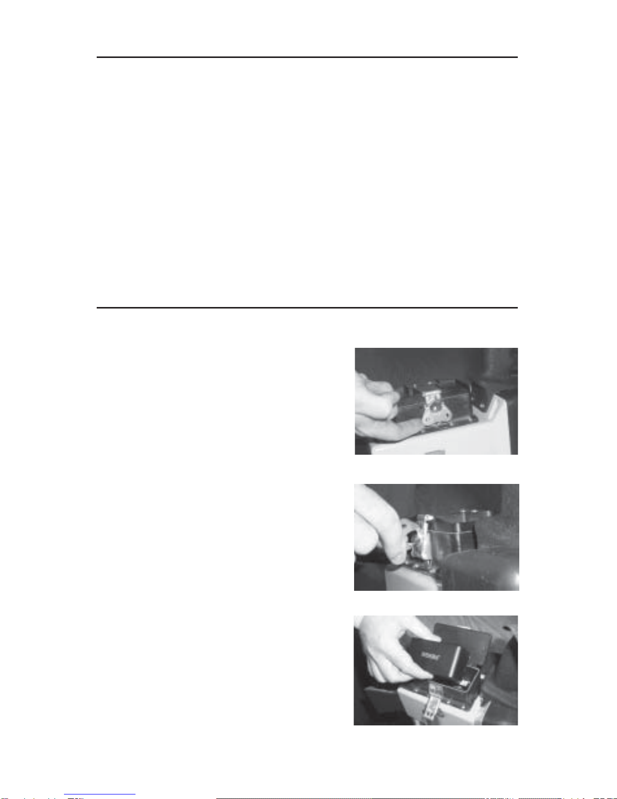
3.1 BATTERY INSTALLATION
3.1.1 Place the camera upside
down with the LCD screen facing
you. Loosen the cam-lock fas-
tener by pulling up on the butterfly
shaped handle until it is perpen-
dicular to the battery compart-
ment.Turn the handle towards
you until the cam-lock hook
separates from the latch plate.
Open battery compartment lid.
3.1.2 Place the battery, contact
side down, into the compartment.
With the Duracell battery, it does
not matter which direction the
battery is placed as long as the
contact side is facing down.
3.1.3 Close the lid. Line the cam-
lock hook up with the latch plate
and turn butterfly handle away
form you until totally secure.Push
down on the butterfly handle to
lock.Be sure the butterfly handle
is facing towards the top of the
camera when in the locked
position.

Copyright 2001 International Safety Instruments, Inc. 5
WARNING: Replacement batteries must exactly match the con-
figuration and ratings of the original batteries supplied with the
Surveyor. Use of unapproved batteries may result in system
malfunction or failure which could lead to injury or death.
3.2 RED BUTTON OPERATION - ON/DELAY OFF MODE
3.2.1 To turn the camera on, push
the red button for about one
second then release.The camera
will take between 15 to 30 seconds
to warm up and provide a thermal
image. To turn the camera off,
push and hold the red button until
theimage disappears.
3.3 BLACK BUTTON OPERATIONS
3.3.1VIDEO MIX (if installed)
3.3.1.1 To initiate theVideo Mix
feature, push and hold down
the black button.To endVideo
Mix feature, release the black
button.(See section 4.2 for
explanation of this feature.)
3.3.2 REVERSE POLARITY (if in-
stalled)
3.3.2.1 To initiate the Reverse
Polarity feature, push or click
the black button.(See section
4.3 for explanation of this
feature.)
3.4 KEVLAR® HANDSTRAP
3.4.1 On the right side of the camera is a fire retardant adjust-
able handstrap by which to hold the camera.(See maintenance
section for replacement procedures.)
3.4.2 The handstrap can be used by either sliding your hand
through it and gripping the camera or, grasping the handstrap by
placing your hand over and through the top of the straps.
3.4.3 To loosen the hand strap, grip the buckle tab and push
away from your body parallel to the strap.To tighten, simply pull
on the free end of the strap to pull through the buckle.

Copyright 2001 International Safety Instruments, Inc.
6
3.5 KEVLAR® NECKSTRAP
3.5.1 Attach neckstrap to “D” ring located at the rear handstrap
connection.Neckstrap can be worn several different ways and is
up to the users discretion.
3.6 BATTERY LIFE INDICATOR
3.6.1 A battery life icon is visible on the lower left hand side of
the screen and indicates the level of battery power available.
NOTE:It is recommended to have a full battery indicated before
entering a fire scene.
3.6.2 When the battery level decreases to approximately 5
minutes of battery life left, the words “Low Battery” will flash on
the screen.Operator should immediately leave the hazardous
environment.
3.7 SENSORTEMPERATURE WARNING
3.7.1 Should the internal temperature of the camera begin to
reach it’s operating limit, the words“Critical Failure Immanent” will
appear on the screen.Operator must immediately leave the
hazardous environment when warning appears.
NOTE:Due to the numerous environmental variations between
fire scenes, there is no way to predict the amount of time before
sensor shutdown after the warning appears on screen.
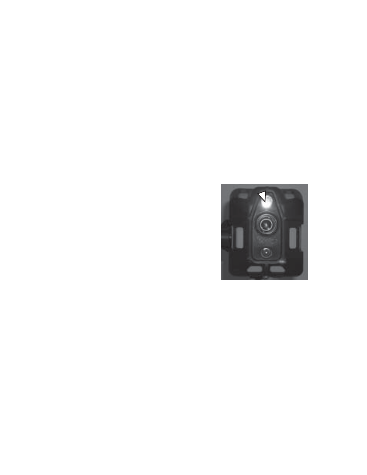
Connecting External Battery Charger
Internal Battery
Compartment and
pods for setting
time, date, and
temperature
Illustration 1
12
3

Copyright 2001 International Safety Instruments, Inc. 7
3.8 SETTING DATE & TIME (see Illustration 1)
3.8.1 Place the camera upside down with the LCD screen facing
you. Loosen the cam-lock fastener by pulling up on the butterfly
shaped handle until it is perpendicular to the battery compart-
ment.Turn the handle towards you until the cam-lock hook
separates from the latch plate.Open battery compartment lid.
Remove battery if present.
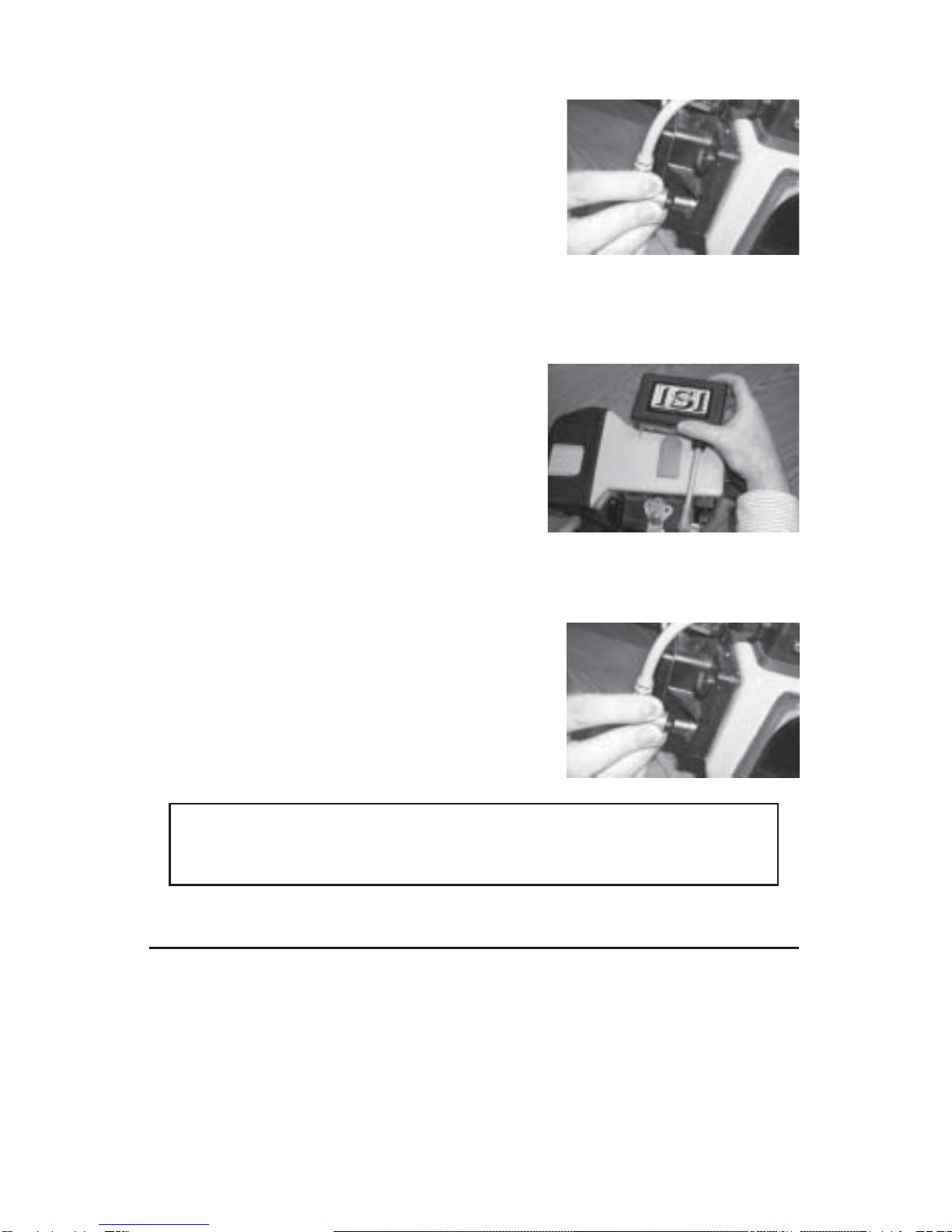
3.8.2 Plug the power cord to the external charger. Remove the
dust cap from the external charging jack on the top side of the
camera (1).Line up the charger plug with the jack using the
guide.With very little force, slide the plug into jack (2). Screw the
lock ring down.Plug the external charger into an AC outlet.
3.8.3 Turn the camera on by pushing the red button.Locate the
cursor pods “A” and “B” inside the battery compartment (3).Using
a toothpick or end of a paper clip, depress and hold pod ”B” down
until the date and time appear on the screen.The hour should be
highlighted and blinking.Adjust the hour by pressing the“A” pod
until displayed hour is shown.To move to the next setting, press
pod “B” and to adjust the setting press the “A” pod.This process
will take you through minutes, seconds, month, date, century (first
two digits of the year) and the decade (last two digits of the year).
If no button is depressed for a short time, all the changes are
saved and the date and time disappear from the screen.
3.8.4 Place the battery (contact side down) into the compart-
ment.With the Duracell battery, it does not matter which direction
the battery is placed as long as the contact side is facing down
(see section 3.1).
3.8.5 Close the lid.Line the cam-lock hook up with the latch plate
and turn butterfly handle away from you until totally secure.Push
down on butterfly handle to lock. Be sure the butterfly handle is
facing towards the top of the camera when in the locked position.
3.9 SETTINGTEMPERATURE SCALE (see Illustration 1)
3.9.1 Place the camera upside down with the LCD screen facing
you. Loosen the cam-lock fastener by pulling up on the butterfly
shaped handle until it is perpendicular to the battery compart-
ment.Turn the handle towards you until the cam-lock hook
separates from the latch plate.Open battery compartment lid.
Remove battery if present.
3.8.2 Plug the power cord to the external charger. Remove the
dust cap from the external charging jack on the top side of the
camera (1).Line up the charger plug with the jack using the
Copyright 2001 International Safety Instruments, Inc.
8
guide.With very little force, slide the plug into jack (2). Screw the
plug down.Plug the external charger into an AC outlet.
3.8.3 Turn the camera on by pushing the red button.Locate the
cursor pods “A” and “B” inside the battery compartment (3).Using
a toothpick or end of a paper clip, depress and hold both the “A”
and “B” pods buttons simultaneously until the screen reads
“Select Crosshairs”.Press the “A”pod down twice.The screen
should read “SelectTemp Scale”.Press the “B” pod down to
reveal the current scale.Press the “A” pod to switch between °F
and °C.If no button is pressed for a short period of time, the
change will be saved and the “SelectTemp Scale” will disappear
from the screen.
4.0 OPTIONS & ACCESSORIES
4.1 PYROMETER
4.1.1 The pyrometer is a non-
contact temperature measurement
feature that allows firefighters to
estimate the surface temperature of
objects from a remote location.When
the pyrometer is installed, the
internal view finder will be equipped
with small crosshairs in the center of
the screen.To measure the tempera-
ture of an object, place the
crosshairs on the center of the
object. The approximate surface
temperature of the object is displayed on the bottom right corner
of the view finder, and also transmitted to a remote monitor when
used in conjunction with the internal transmitter.
The Pyrometer measures the temperature of an area one foot in
diameter to every 30 feet of distance.For example, if the object is
90 feet away, a 3 foot diameter is used to determine the tempera-
ture.If the object is 7.5 feet away, the diameter is only 3 inches.
The further away the object, the more ambient air influences the
temperature reading.The readout is in graduations of approxi-
mately 4oF or 2oC.
4.2VIDEO MIX (see Illustration 1)
4.2.1TheVideo Mix option is a combination of a thermal and
video image.The Video Mix ratio is user settable between 80%
and20%.

Copyright 2001 International Safety Instruments, Inc. 9
4.2.2To adjust its setting, place the camera upside down with the
LCD screen facing you.Loosen the cam-lock fastener by pulling
up on the butterfly shaped handle until it is perpendicular to the
battery compartment.Turn the handle toward you until the cam-
lock hook separates from the latch plate.Open battery compart-
ment lid.Remove battery if present.
4.2.3 Plug the power cord to the external charger.Remove the
dust cap from the external charging jack on the top side of the
camera (1).Line up the charger plug with the jack using the
guide.With very little force, slide the plug into jack (2). Screw the
locking ring down.Plug the external charger into an AC outlet.
Turn the camera on by pushing the red button.
4.2.4 Locate pod “D” inside the battery compartment and using a
jewelers screwdriver, adjust the mixture to your desired setting
(3).Test the setting by pushing and holding down the black
button.
4.3 REVERSE POLARITY
4.3.1The reverse polarity option changes the heat signature from
white hot to black hot.Provides greater clarity and definition to
the scene. Black-hot or white-hot is indicated on the video display.
Polarity is transmitted to the video receiver.
4.4 PISTOL GRIP HANDLE
4.4.1 To install the pistol grip handle, line up the handle with the
three threaded inserts and use the three screws to secure the
handle to the camera.Use the supplied washers on the screws.
4.4.2 To use the handle, place your hand through the wrist strap
and grip firmly.
4.5 SURVEYORTRANSMITTERS
4.5.1 CONNECTING THEVIDEO-LINK PLUS.
4.5.1.1 TheVIDEO-LINK PLUS
transmitter connects to the side
rail connector on the left side of
the Surveyor camera. You must
line up the side rail connector -
it can only go in one way.DO
NOT FORCE.
4.5.1.2 Connect the 8 inch di-pole antenna to theVIDEO-
LINKPLUSTransmitter.
Copyright 2001 International Safety Instruments, Inc.
10
4.5.1.3 Remove the cap from the 4 way wire connector on
the camera.
4.5.1.4 Connect theVIDEO-
LINK PLUSTransmitter to the
Surveyor using the 4 way wire
connection located below the
view finder, toward the back of
the Surveyor.
4.5.1.5 Turn the Surveyor ON - this automatically turns on
theVIDEO-LINK PLUS.
4.5.2 CONNECTING THE DUAL-
CHANNEL 2.4
4.5.2.1 Slide the transmitter
onto the side rail on the left
hand hide of the camera.You
must line up the side rail
connector - it can only go in
one way.DO NOT FORCE.
4.5.2.2 Remove the cap (if present) off the 4 pin connector of
the camera.
4.5.2.3 Attach theTransmitter’s
cable to the 4 pin camera
connector by lining up the slot in
the transmitter’s connector with
the rail of the camera’s connec-
tor. Be sure NOT to force the
connection.
For receiver set-up and operation, see the appropriate
wireless communication manual.
5.0 INSPECTION AND MAINTENANCE
5.1 GENERAL INSPECTION AFTER EACH USE
NOTE: The thermal imaging camera should be tested before
each use.
5.1.1 Inspect the camera, batteries and optional transmitter for
structural, heat and/or chemical damage.Cameras with signs of
damage should be taken out of service and returned to the
factory for repair.(Call ISI customer service at 888-474-7233 for a
return authorization number.)

Copyright 2001 International Safety Instruments, Inc. 11
5.1.2 Inspect side strap, wrist strap and neckstrap along with
neckstrap clip and “D” ring for damage and/or fraying.If any strap
is frayed or damaged, replace before next use.Check that all
screws are tight.
5.1.2.1 To replace side strap, using the proper torx driver,
remove the two screws and washers.Attach the new side
strap and secure in place with the washer and screw.
5.1.3 Inspect visor and front bumper for cracks, rips or wear.
Special attention should be given to the areas used for side strap
connection.
5.1.4 Inspect the battery compartment gasket for cracks and/or
misalignment.Replace before next use if cracks are present.
5.1.5 Check that warning labels are intact and legible.
5.1.6 Inspect charging port for visible damage.Ensure dust cover
is attached.
5.1.7 Inspect pyrometer window for cracks.
5.2 PERIODIC INSPECTION
5.2.1 WEEKLY INSPECTION
5.2.1.1 Inspect battery charger for proper operation and
LED indicators. (See battery charger manual for details.)
Check charger contact points for corrosion or damage.
5.2.1.2 Inspect all batteries for damage, leakage, and
corrosion, and for damage to the contacts.
5.3 BATTERY MAINTENANCE
5.3.1 INTERNAL BATTERY CHARGING
5.3.1.1 Place battery in camera (see section 3.1).
5.3.1.2 Plug the power cord to the external charger. Remove
the dust cap from the camera charging jack.Line up the
charger plug with the jack.With very little force, slide the plug
into the jack.Screw the plug down.Plug the external charger
into an AC outlet.Depending on the existing battery power
level and the age of the battery, a full charge will take be-
tween 3 to 5 hours.The LED light on the camera will be solid
red while charging and solid green while cooling down.When
the battery has been fully charged, the LED light will flash
between red and green.

Copyright 2001 International Safety Instruments, Inc.
12
5.3.2 EXTERNALBATTERYCHARGING
5.3.2.1 All new batteries must be fully charged before first
use.A normal battery will take between three to five hours to
charge. Simply place battery in the charger, check to see the
green light is on, and allow to fully charge.
NOTE:A fully or partially
charged battery will indicate
“empty” when first put into
charger.Time to register or fully
charge will depend upon the
amount of charge in battery
when first placed onto the
charger.
5.3.2.2 It is not recommended
that a battery be left in the
camera when not in use unless it
is being externally charged for
the battery will drain more rapidly
than if stored outside of the
camera.
5.3.3 BATTERY REFRESHING
5.3.3.1 To refresh the battery, simply place on the charger
and push the refresh button.The yellow light should be on to
indicate the refresh cycles.A complete refresh should take a
minimum of eight to ten hours.
5.3.2.2 Refreshing of batteries should take place about every
three to six months depending upon usage.When a notice-
able difference in time performance is apparent on fully
charged batteries, a refresh of the battery(s) is recom-
mended.
NOTE:Please read the battery charger manual included with
the camera for additional information.
5.4 CLEANING
5.4.1 CAMERA HOUSING
5.4.1.1To clean the camera housing use a medium bristle
brush or sponge and a mild non-detergent dishwashing soap.
Do not use bleach or any other compound containing chlo-
rine.

Copyright 2001 International Safety Instruments, Inc. 13
5.4.2 OPTICAL LENS & PYROMETER WINDOW
5.4.2.1 To clean the optical lens use lens paper and photog-
raphy grade lens cleaner available at your local camera store.
Do not use paper towels or any other abrasive material for
they will scratch the lens.
6.0 WARRANTY
International Safety Instruments, Inc.warrants this product to the original
owner to be free of defects in material and workmanship for one year
from the date of purchase. ISI’s obligation under this warranty is limited to
the replacement or repair, at ISI’s option, of any proven defective part if
returned to ISI in Lawrenceville, GA, or an authorized distributor.Shipping
charges shall be prepaid by the owner.Upon inspection, ISI will repair all
products that prove to have been defective from normal use and service.
This warranty does not apply to equipment malfunction or damage
resulting from accident, alteration, misuse, or abuse of the equipment
including, but not limited to, power surges, over exposure to heat, defec-
tive power supply, abnormal wear and tear or other perils outside the
design tolerances of the system.In addition, this warranty does not apply
to elastomer or rubber components since they can be adversely affected
by undue exposure to heat, sun, water, ozone, or other deteriorative
elements.The decision as to what constitutes normal use shall be made
solely by ISI.
To maintain this warranty, the purchaser must perform maintenance and
inspections as prescribed in the operation and maintenance manual
which shall include prompt replacement or repair of defective parts.
This warranty is expressed in lieu of all other warranties, expressed or
implied, and all other obligations and liabilities on ISI’s part.ISI neither
assumes nor authorizes any other firm or person to assume on ISI’s
behalf any liability in any way connected to the sale of ISI Products.
Batteries, battery charger, and cables are covered by separate
manufacturer’s warranties and are not covered by this ISI warranty.

Copyright 2001 International Safety Instruments, Inc.
16
ATTENTION
ByorderoftheUnitedStatesDepartmentofCommerce
BureauofExportControl,thisThermalImagingCamera
maynotbeshippedorhand carried outside theborders
ofthe owner’shomecountrywithoutfirstobtainingthe
properexportlicensefromtheirrespectivegovernment
departmentortheUnitedStatesDepartmentofCom-
merce. Violation ofthiswarning may resultinfine or
imprisonmentaccordingtotheUnitedStatesExport
AdministrationRegulations,15CFR,Parts730-774.
INTERNATIONAL SAFETY INSTRUMENTS, INC.
922 Hurricane Shoals Road Lawrenceville, GA 30043
770-962-2552 888-ISI-SAFE (toll free) FAX 770-963-2797
Thermal Imaging System
SURVEYOR
Table of contents
Other International Safety Instruments Thermal Camera manuals


