International Thermal Research Prospector User manual

20101112 rev6
International Thermal Research
www.pioneerspaceheaters.com i
Installation and
Operating Manual
Revised for Drill Shack Modification
CERTIFIED TO CSA A D UL STA DARDS

ii International Thermal Research
Table of Contents
Table of Contents .........................................................................i
Table of Contents ........................................................................ ii
Overview....................................................................................1
1. Safe Operation ......................................................................1
2. DOs and DO NOTs .................................................................2
3. Components..........................................................................4
4. Installation ...........................................................................6
5. Operation ........................................................................... 12
6. Oil Control alve.................................................................. 14
7. Maintenance ....................................................................... 15
8. Trouble Shooting ................................................................. 16
READ THESE I STRUCTIO S A D SAVE FOR FUTURE REFERE CE

International Thermal Research
www.pioneerspaceheaters.com 1
Overview
Thank you for purchasing International Thermal Research’s
(ITR) Prospector space heater.
The Prospector Heater is a vaporizing-type oil burner space
heater with a simple, effective design that produces radiant and
convection heat through the efficient combustion of liquid fuel.
With regular maintenance and proper operation your heater will
function satisfactorily for many years.
The heat output range for your modified Prospector heater is 20,000 to 35,000 BTU’s.
This is sufficient capacity to heat areas such as cabins, workshops, small warehouses, etc.
Table 1: General Information
Oil Consumption Chimney draught
Nominal heat
output min max min Max Weight Flue diameter
35,000 BTU/Hr 0.32 US Gal/h 0.41 US Gal/h .050” W.C. .060” W.C. 58 Lbs Ø6 inches
10,2 kW 1,20 Liter/h 1,56 Liter/h 12,5 Pa 15 Pa 26 kg 152,4 mm
1. Safe Operation
Proper installation, operation and maintenance procedures laid out in this manual, as well
as local government requirements, must be followed to insure the safe operation of your
Prospector. CSA standard B139, Installation Code for Oil Burning Equipment, UL896, or
NFPA#31 are standards that apply to this equipment.
Make sure you read, and understand these instructions and save them for future
reference. If you have any questions or don’t understand anything in this manual, contact
your authorized ITR dealer.
Make sure you read and
understand this manual
before installing and
operating your
Prospector. If you have
any questions, or
require any explanation,
please contact your
authorized ITR dealer.

2 International Thermal Research
. DOs and DO NOTs
All heaters must be installed according to the installation rules mandated by local,
state/provincial and federal government authorities. These regulations deal with
various matters including heater and flue set backs and fuel storage. DO determine
what regulations apply in your local area. DO OT install the heater or flue unless
installation conforms with the regulations governing your location.
All heaters and stoves, whether they burn solid or liquid fuel, exist for one reason – to
produce heat. Therefore common sense says that all heater parts will be hot when the
unit is operating. DO OT touch heater parts if the heater is running. You’ll get
burned.
Your heater is designed to burn clean #1 and #2 diesel fuel. If you burn any other fuel
or burn contaminated diesel, you will void your warranty, cause damage to the fuel
control valve (Toby) and may cause a fire or even an explosion. DO use only the right
fuel. DO OT use any other fuel, under any circumstances.
Fuel delivery from the tank to the heater is important. Any fuel leaks can result in a
dangerous fire. DO inspect the entire fuel line for leaks before firing the heater. DO
OT start the heater until any leaks are properly fixed.
Because of the unique vaporizing design of the heater, correct draft conditions are
essential for the heater to operate in a satisfactory manner. DO check the draft on the
setup of the heater by using a draft meter and ensure the heater is operating under the
recommended setting. If a draft meter is not present, the draft conditions MUST be
estimated. See the details in the manual for estimating the draft conditions.
All fuel burning heaters require oxygen to operate and they get that oxygen from the
air. DO inspect the space below the burner to make sure there are no blockages and, if
there is any dust or dirt remove it. DO inspect the exhaust flue (stove pipe) to make
sure it is not blocked. DO OT start the heater until any blockages have been
removed.
Oxygen for combustion comes from the air in the same space as the heater and as that
air is used in the combustion process it goes up the exhaust flue. Since you are also in
the same space as the heater, if the air in the room is not replaced, all the oxygen
needed to keep the heater burning, and you alive, will run out. DO make sure that you
have a window or door opened a bit to allow fresh air to enter. DO OT operate the
heater in an air tight room. To do so will lead to oxygen deprivation and, if the
condition continues, will result in death.
During shipping, the S-tube may become dislodged from the center fuel up tube. If the
S-tube has become dislodged, which can be seen through the glass on the lid, the top
of the heater must be removed to position the S-tube over the fuel up-tube. DO OT
operate the heater without initially checking the position of the S-tube.

International Thermal Research 3
DO OT operate the heater without both a complete exhaust stack in place and correct
draft conditions. Excessive carbon will form in the fuel up-tube and will have to be
cleaned out for the heater to function correctly.
DO mount the heater securely to a non-combustible floor. If a heater is not solidly
secured, and it gets knocked over, it will spill the burning fuel all over the floor. This
will create a serious fire hazard that could burn down the building housing the heater.
DO OT start the heater until it is properly secured.
All liquid fuel heaters run best when they are level. DO make sure your heater is level
before you start it.
If, after the heater has been fired, you smell smoke or exhaust fumes, shut the heater
down immediately and examine the stove pipe for leaks or loose fittings. DO OT
continue to operate the heater until any leaks are repaired. The fumes are poisonous.
DO vent all exhaust gases outside.
DO OT ever attempt to relight the heater when it is hot. If the unit is shut down for
any reason DO wait until it cools down to room temperature before re-firing.
All heaters, regardless of the type or make, can malfunction and all manufacturers
recommend that heaters are not left running unattended. DO OT leave the heater
running unattended. The Prospector is mechanically capable of operating unattended,
but if there is a malfunction ITR accepts no responsibility or liability for any damage
caused, regardless of the type or extent of the damage. THIS PARAGRAPH
CO TAI S LA GUAGE THAT LIMITS THE MA UFACTURER’S LIABILITY.
DO install carbon monoxide and smoke detectors in the same room as the heater;
The Canadian Standards Association (CSA) has some additional consumer tips for
space heaters.
Some of those tips are:
DO OT hang wet clothing above the heater to dry it. The clothing can catch fire
as it dries
DO supervise young children when in the same room as the heater
DO OT keep gasoline, solvents or other flammable or vapourizing liquids in the
same room as the heater.
More tips can be found on http://www.csa.ca/consumers/consumer_tips/.

4 International Thermal Research
3. Components
A.) Prospector major external components
Heater Shell (1) – The
heater shell assembly is the
area of the heater
containing the perforated
burner shell.
Top Lid (2) – Contains a
sight glass to observe the
flame.
Guard (3) – Perforated
shield surrounding the
Prospector
Valve Heat Shield (4) –
Shield between control valve
and burner shell.
Toby Oil Control Valve (5) – Located on the side of the heater and controls the
amount of gravity fed fuel supplied to the burner. Turning the control knob will
allow more or less fuel to enter the burner. See sections 5 & 6.
Drain Valve (6) – To fill up the primer cup or to drain fuel from the control valve.
Fuel Connection (7) – ¼” NPT female threaded fitting
Fuel shut off valve (8) – Opens or closes the flow from the fuel tank to the Oil
Control alve .
Flue Collar (9) – To attach a Ø6” Flue stack.
Reamer Tool (10) – To clean the Up-Tube from soot and carbon build up.
Primer Cup (11) – Attached with a chain and used to start-up the heater.
Removable Handle (12) – Used to open the lighting port or top lid. Do not leave
the handle on the unit when heater is running. Handle gets too hot to touch.
Draft regulator (13) – To maintain a stable draft

International Thermal Research 5
B.) Prospector major internal components
Up–Tube (20) – Receives fuel from the oil control valve and permits fuel vapours
to flow into the S-Tube (25) during operation.
High Fire Ring (21) – Clean below High Fire Ring periodically, remove any build up
of soot or hard carbon deposits and vacuum.
Burner Shell (22) – Area of the heater where combustion occurs. The perforated
Burner Shell contains an up-tube (20) welded to the base of the shell and a
removable, capped S–Tube (25) which sits over the welded up-tube. The Burner
Shell is permanently mounted inside the Burner Shell Assembly (1) and can be
accessed by removing the Top Lid (2).
Burner Base (23) – Bottom of Burner Shell (22). Periodic cleaning from soot and
carbon build up required.
Burner Heat Shield (24) – Heat shield to keep heat inside the Burner Shell and
away from the bottom of the Prospector Unit.
S-Tube (25) – The large capped tube in the center of the perforated Burner Shell is
the S-Tube. During shipping, the S-tube may become dislodged from the center fuel
up tube (20). If the S-tube has become dislodged, which can be seen through the
glass on the lid, the top of the heater must be removed to position the S-tube over
the fuel up-tube. DO OT operate the heater without initially checking the position
of the S-tube.
During operation, fuel flows through the Up-Tube (20) where its level is gravity
maintained with the Toby Control alve (4). Fuel vaporizes due to combustion heat
and is expelled from the up-tube, down through the S-tube and into the perforated
burner shell where it ignites.
Note: If any parts appeared damaged, do not operate the heater. Contact your
authorized Prospector Dealer.

6 International Thermal Research
When unpacking the heater, remove any packing material from the side of the
burner canister and around the air intake area.
4. Installation
A.) Location and Mounting
The Prospector heater may be placed on a flat level surface made of material that
can resist heat. Hardwood, plywood, concrete, etc. are acceptable. The Prospector
should not be mounted directly on a carpeted floor. Use a solid platform or rigid
heat resistant material between the carpet and the heater.
Ideally a large open space would best suit the heater. The surfaces of the heater
and the flue stack will be generating heat and should be taken into consideration
when mounting the heater.
The minimum standard clearance between the heater and any combustible building
construction other than the floor is 20 inches (51 cm). The minimum standard
clearance between the exhaust vent pipe and any combustible building construction
is 12 inches (30.5 cm).
The minimum standard clearance between the heater and any metal building
construction is 1 inch (2.5 cm). The minimum standard clearance between the
exhaust vent pipe and any metal building construction is 1 inch (2.5 cm). Note that
these metal surfaces cannot make contact with combustible surfaces. If the metal
surfaces are placed on top of combustible surfaces, they must be separated with
non-combustible spacers and spaced such that the temperature rise of the
combustible surface does not exceed 65° C (149° F).
Metal surfaces mentioned above include:
•
••
•Stainless steels (AISI types)
•
••
•Carbon steel sheets and plates
•
••
•Cast iron and low-alloy cast steels
•
••
•Galvanized and sheradized steels and iron and galvannealed steel
•
••
•Aluminized and calorized steel
•
••
•Chromized steel
•
••
•Ceramic coated carbon steels
•
••
•High-alloy cast steels
An unlevelled heater will not operate properly and could be dangerous. Adjust the
heater perfectly level in all directions before mounting.
The heater should be securely mounted to the floor. The legs contain a ¼” hole for
directly fastening the heater to the floor.
International Thermal Research 7
B.) Exhaust Flue Stack and Draft
OIL BUR I G APPLIA CES MUST BE CO ECTED TO FLUES HAVI G SUFFICIE T
DRAFT AT ALL TIMES TO E SURE SAFE A D PROPER OPERATIO OF THE BUR ER.
All heaters must be installed according to the installation rules mandated by local,
state/provincial, and federal government authorities. These regulations deal with
various matters including heater and flue set backs and fuel storage. DO determine
what regulations apply in your local area. DO OT install the heater or the exhaust
flue stack unless the installation conforms with the regulations governing your
location.
The Prospector does not come with an exhaust flue stack. Blue stove pipe or All-
Fuel “L” type vent capable of continuous use for flue gas temperatures up to 1000˚F
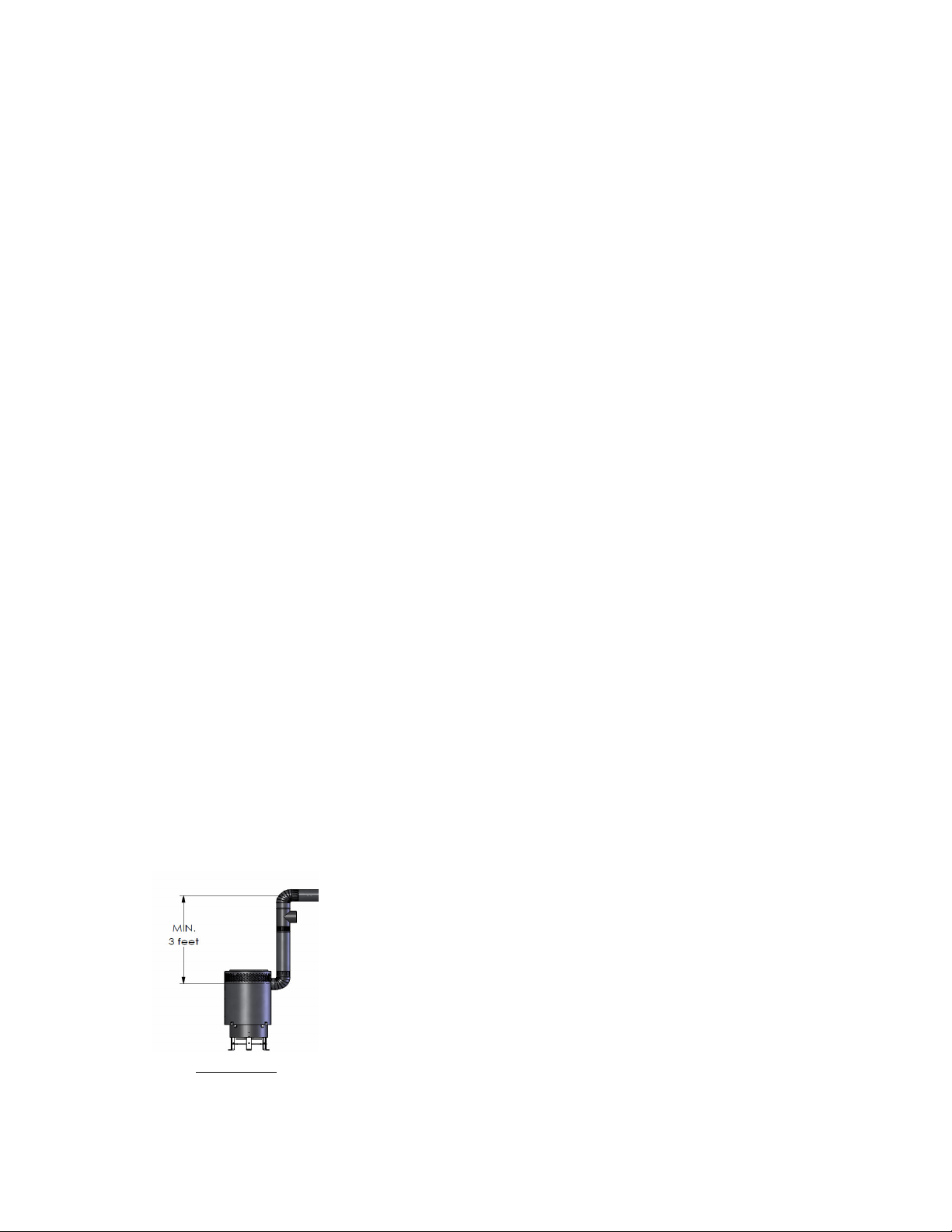
may be used. Always use a 6 inch diameter, ninety degree elbow off the heater.
Attach a 90 degree elbow directly to the heater. The non crimped end of the
exhaust elbow is designed to slide over the heater exhaust collar. Fix the elbow to
the heater collar. Attach a minimum of three feet of the same 6 inch diameter flue
stack to the elbow. After this point, you may transition into a larger diameter stack.
Appropriate parts for the appropriate flue stack must be purchased at your local
heating and ventilation companies. As all installations differ, it is necessary that you
follow all local, state/provincial, and federal guidelines in selecting the type,
method, and location of the exhaust flue stack for your particular situation.
Before hooking up the Prospector to a chimney flue stack (6 inch diameter), check
if the chimney is in good condition and that the quality of the flue pipe will allow
sufficient draft.
DO OT connect horizontal exhaust stacks directly off the heater. The heater will
not operate correctly and will not stay lit. The heater requires a 90 degree exhaust
elbow and a minimum three foot vertical rise before further elbows and exhaust
stack lengths are added. A maximum horizontal length of 3’ is allowed. Make sure
to have a ¼” slope rise per foot minimum. Each foot of horizontal length requires
1.5 feet of additional vertical stack height.
The minimum flue stack height for an angled roof with top opening exit and a
vertical only flue stack is 9 feet (2.74 m). For a vertical sidewall exit with a
horizontal run of three feet, the minimum vertical stack height is 13 feet (4 m).

8 International Thermal Research
The chimney flue should extend at least 2’ (0.6 m) above the highest roof surface or
structure within 10’ (3.0 m) horizontally of the chimney to prevent down drafts.
Exhaust location: angled
roof (standard
configuration)
Exhaust locatio
n:
vertical sidewall
(optional) configuration)
Prospector
heater
with a three foot
horizontal run.
13 feet of vertical
stack height in total
is required versus
the standard 9 feet.
SAMPLE EXHAUSTS:
ROOF EXIT
AND SIDEWALL EXIT

International Thermal Research 9
Install the included draft regulator which is necessary in order to maintain stable
draft in certain conditions.
DRAFT CO DITIO S All heaters require the proper draft.
If a draft meter is available, set the heater to the recommended water column
reading. The recommended draft for the Prospector is between .040-.060 inches
water column. This is measured 18” (45cm) up the stack, before the draft regulator,
and with the final exhaust stack configuration in place. Follow the manufacturer’s
instruction for the installation, location, and adjusting of the draft regulator.
If a draft meter is not available, estimate the draft (see below).
TO ESTIMATE THE DRAFT Set up the heater with the final exhaust stack
configuration in place. Start the heater, and set the heater to operate at the #1
setting (position indicated by the first raised notch on the fuel control
valve) only. Do not operate the heater at any other setting or the flame will be
distorted. After 10 minutes of operation, view the burner flame through the glass lid
on the top of the heater. Look for the level of the tips of the flame relative to the
top of the S-tube. The correct draft is approximated by the flame tips at the same
height as the top of the S-tube.
TO ADJUST THE DRAFT In general, the draft can be increased by increasing the
existing vertical stack height. Decrease the draft by decreasing the existing vertical
stack height. If a draft regulator is present, adjust the settings on the draft
regulator until the desired draft setting is reached. Follow the manufacturer’s
instructions on use of the regulator.
HIGH DRAFT
:
The tips of the
flame are at a
level lower than
the top of the “S”
tube.
CORRECT DRAFT
:
The tips of the flame
are at the same level
as the top of the “S”
tube
LOW DRAFT
:
The tips of the
flame are at a level
higher than the top
of the “S” tube.
10 International Thermal Research
The Prospector emits very little carbon and soot into the flue system. However it
may be convenient to design your flue system so it can be brushed clean if
necessary.
For safe operation, it is highly recommended that the installed exhaust system be
inspected by a qualified professional to ensure the suitability of the type and
method of the installation.
During operation, the heater produces harmful carbon monoxide (CO) and other
gases. To prevent CO poisoning, ensure the exhaust stac sections fit together
snugly and that the exhaust gases are properly vented through the roof or sidewall.
C.) Venting and Air Supply
The heater consumes about 4000 ft3 of air per 1 US gallon of oil. This air enters the
heater through the air inlets and exits the chimney as combustion gas.
The Prospector should be installed in a well ventilated area that allows the
entrance of outside fresh air.
Connecting to Oil Tank
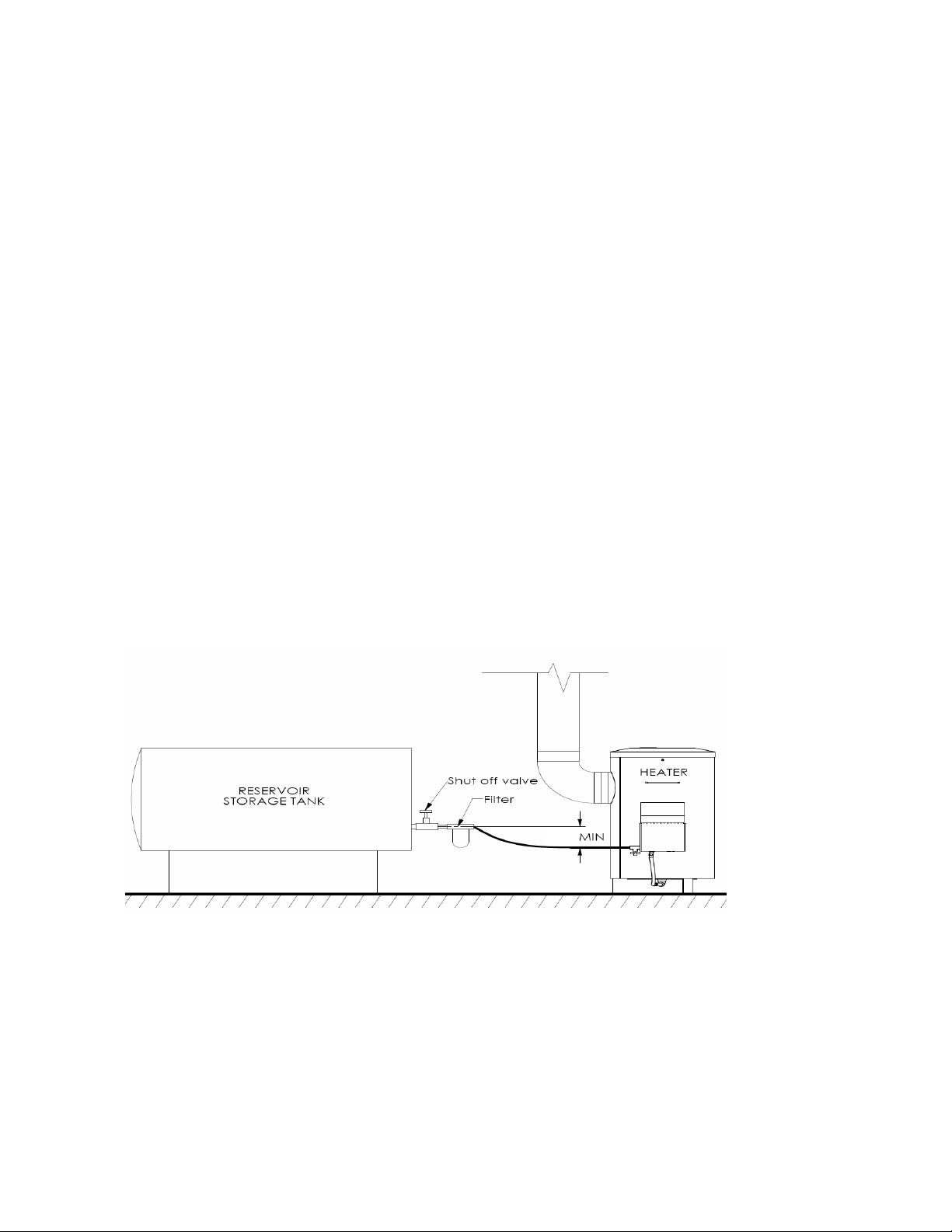
The external oil tank is to be installed in accordance with the manufacturer’s
instructions and the standard to which the tank has been manufactured.
Make sure that the tank outlet is 24” (60 cm) higher than the inlet of the oil control
valve (gravity fed). A good quality filter should be placed at the tank exit to ensure
a clean supply of fuel.
24”
International Thermal Research 11
The fuel line must be clear of any air prior to operating the heater. A fuel line kit or
a solid fuel line both must be cleared of air once the fuel line is attached to the
heater (shown below)
When the fuel tank is installed outdoors in very cold temperatures, it is preferable
to use #1 diesel fuel and a ¾” fuel line to avoid any viscosity problems.
The fuel line can be connected to the oil control valve using a ¼” NPT male fitting.
INSTALLATION OF THE HEATER, FLUE STACK AND FUEL TANK MUST BE INSTALLED IN
ACCORDANCE WITH THE REGULATION OF AUTHORITIES HA ING JURISDICTION, NFPA
#31, CSA STANDARD B139. AND UL896.
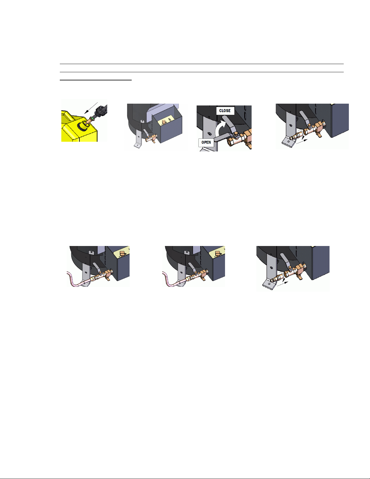
USI G A FUEL LI E KIT
Place the fuel line filter with attached hose into the
fuel of the fuel tank. Remove the brass nipple from the kit and apply sealant to
the threads. Screw into the ball valve fitting of the heater and tighten until leak
free. Do not over tighten or the threads will be damaged and leakage may occur.
Connect the fuel line to the heater using the female quick connect fitting. Turn the
heater ball valve lever to the OPEN position and open the fuel drain valve.
Squeeze the primer bulb until fuel flows in a steady stream from the drain valve.
Catch the fuel in a separate container, then close the fuel drain valve. The fuel line
is clear of air.
USI G A SOLID FUEL LI E
Connect the solid fuel line to the heater. Turn the
ball valve lever to the OPEN position and open the fuel drain valve. Start the fuel
flowing from the fuel tank and wait until fuel flows in a steady stream from the
drain valve. Catch the fuel in a separate container, then close the fuel drain valve.
The fuel line is clear of air.

12 International Thermal Research
5. Operation
The Prospector heater requires a break in period between 1 and 2 hours. During this
period, some smoke and fumes may be generated from the heater shell itself; make sure
there is enough ventilation for the smoke and fumes to escape the living or operating
areas.
A.) Starting the Prospector Heater
To start the Prospector Heater:
DO OT OPERATE THE HEATER WITHOUT BOTH A COMPLETE EXHAUST STACK
IN PLACE AND CORRECT DRAFT CONDITIONS. EXCESSI E CARBON WILL FORM
IN THE FUEL UP-TUBE AND WILL HA E TO BE CLEANED OUT FOR THE HEATER
TO FUNCTION CORRECTLY.
DO NOT USE ANY UNAUTHORIZED FUELS OR MIX DIFFERENT FUELS. ONLY CLEAN
UNCONTAMINATED DIESEL #1 OR #2 FUEL IS TO BE USED. USING ANY OTHER FUELS
COULD CAUSE A FIRE AND/OR EXPLOSION. DO OT USE GASOLINE, CRANKCASE OIL,
OR ANY OIL CONTAINING GASOLINE.
•Check for any leaks in the fuel system. Locate and repair any leaks and/or clean any
spills before igniting the heater.
•Check the exhaust flue stack for any blockage or anything that might obstruct the
exhaust gases. The flue stack must be vented outdoors. Do not let any exhaust gas
flow into any living or operating areas.
•Check the exhaust flue stack and the attachment point to the heater for any leaks.
Correct any problems before igniting the heater.
•Check the airway around the base of the heater to ensure that the heater receives a
clear, unobstructed supply of combustion air.
•Open the fuel shut-off valve from the fuel tank.
•Lift up on Toby alve Actuating Lever fully and release to
ensure that the fuel can run into the float bowl of the valve.
•Place the primer cup below the fuel drain valve located beside
the Toby valve. Open the drain valve and allow the fuel to
drain into the primer cup. Close the drain valve once the cup is
full.

International Thermal Research 13
•Open the lighting port lid on the side of the burner shell
and insert the cup inside the heater to the gap just beyond
the high fire ring and before the circular plate. Pour the
contents of the cup onto the burner base by turning the
cup upside down. This will create a puddle of fuel at the
burner bottom. Do not pour the fuel onto the ring or
circular plate.
•When the burner is being lit, it is usually desirable to use a
match or gas lighter and a small ball of tissue paper for
lighting. Use the paper to clean the primer cup of the
remaining oil and place it in the cup.
•Insert the cup with the paper inside the burner through the
lighting port and position it at the same position as the
“pour” position. Light the paper and turn the cup upside
down so that the burning paper lands in the puddle of fuel
at the bottom of the burner.
•Take the primer cup out and close the lighting port.
•Place the control knob on the Toby control valve to the first raised “I” mark setting
(LOW) next to the “O” mark.
•Wait ten to fifteen minutes for the flames to settle down before setting the control
knob on the Toby control valve to your desired temperature. The “0” is the OFF
setting and a half turn counter clockwise is the highest fuel setting on the burner.
•If the flame dies out, wait for the heater to cool down to room temperature before
repeating the starting procedures.
DO NOT ATTEMPT TO START OR RE-IGNITE THE BURNER WHEN THE BURNER IS HOT.

14 International Thermal Research
•Do not leave a heater running unattended. ITR accepts no responsibility for any
damages caused by leaving the heater running unattended.
B.) Turning off the Prospector Heater
To turn off the Prospector Heater:
•Turn the control knob on the TOBY Oil alve to the OFF position marked “0” on the
lid.
•Turn off the Fuel Shut Off alve from the fuel tank to the heater.
•The flame will die out in about five minutes.
ALWAYS KEEP THE OIL AL E TURNED OFF WHEN THE HEATER IS NOT OPERATING.
6. Oil Control Valve
A.) Toby Oil Valve
The TOBY Oil alve is a continuous flow level control valve designed for controlling
fuel flow to the Prospector heater.
TOBY Oil alves are factory preset to work with your heater. Do not tamper with it.
If you have questions or concerns, please contact your authorized Prospector
Dealer.
TOBY Oil alves are very simple to operate; the key parts to operating a TOBY
alve for the Prospector are the Control knob and the actuating lever. The control
knob controls the fuel flow rate and can be rotated counter clockwise from the off
position, which is the “0” marked on the lid to the high fire position, which is the
last “I” mark on the lid. The Toby alve Actuating Lever allows fuel to run into the
float bowl of the valve when it is placed in an up position.
B.) Toby Valve safety features

International Thermal Research 15
The TOBY Oil alve has two safety features incorporated into the design of the valve.
•High temperature fuel cut off system. If the temperature of the fuel exceeds
100 degrees Celsius (212 degrees Fahrenheit), fuel will be shut off at the
outlet of the valve. Once this occurs, the valve is no longer operable and a
new valve is required for the heater to operate.
•Tilt levelling switch. The Toby Oil alve will shut off at the outlet of the valve
when the angle of the valve exceeds the following: lengthwise 5 degrees,
width wise 15 degrees.
Toby alves are ULC Listed and DIN approved. The Toby valve requires no
maintenance and has no user serviceable parts.
7. Maintenance
A.) Regular Maintenance
To ensure that your Prospector heater operates properly;
•every 750 hours of operation or;
•if the output of the heater appears to be have decreased from the same valve
setting or;
•if the exhaust exhibits smoke
perform the following maintenance:
•In normal operation, carbon and soot will accumulate in the area of the
burner base, heater up tube or underneath the high fire ring. These
deposits must be periodically removed.
•Working on a cold burner, ensure that the fuel control valve on the
heater and the fuel supply to the heater has been turned off. Remove
the burner lid and see if there is any soot around or on the perforated
burner shell or high fire ring. If so, brush off and vacuum clean.
•Loosen and remove any carbon build up in the center up-tube itself.
Remove the bottom heat shield. Locate the clean-out plug at the
bottom of the burner shell assembly. Place the supplied fuel filler cup
below the opening of the clean-out threaded plug. Use a wrench and
remove the threaded plug from the bottom of the assembly. Any
quantity of fuel still present in the fuel line will drain into the filler cup.
Carefully insert the metal cleaning auger into the up-tube and loosen
any hard carbon deposits within the tube by using an up/down twisting
motion of the auger. This will loosen any deposits and allow them to
fall through the opening of the threaded plug. Do not use a side to
side motion or excessive force or you will distort, bend, or

16 International Thermal Research
break the welded up-tube. Continue until the tube is clear of any
accumulated deposits. Replace the clean-out plug into the bottom of
the burner shell assembly and re-tighten. A pipe sealant or other
appropriate sealing compound should be applied to the threads. Check
this threaded plug fitting for any leaks when the heater fuel flow is
again re-started. Re-tighten if necessary.
Additional regular maintenance items include:
•Check for any leaks in the fuel system, cracked hoses or suspect areas where
a leak might occur and correct.
•Check the flue stack for any damage or areas that might allow flue gases to
leak into your heating area and correct.
•Check the flue stack for any blockages and/or soot and remove and correct
•Check for fuel strainer blockage and replace if necessary
•The Toby valve requires no maintenance and has no user adjustable parts
B.) Storing the Heater
On storing the heater for an extended period:
•Perform the previous maintenance steps
•Clean the heater with a rag and spray or wipe with a light mist of oil inside
the burner area and outside to prevent rusting.
•Drain all fuel lines and any fuel from the heater
ATTE TIO : Regular maintenance is required for the Prospector heater to
perform as designed. Failure to maintain the heater as required will not only
void your warranty but can cause the heater to be dangerous to operate.
8. Trouble Shooting
A.) Symptom: Burner does not keep lit, flame shuts off.
Recommendations: On a cold heater
•Check for Fuel Shut off alve in the ON position.
•Check the Control Actuator lever on the Toby alve and ensure it is at the on
position by lifting it up fully and releasing. (This lever does not stay in the
upright position during normal operation)
•Check the Control Knob on Toby alve is not set to “0” or OFF position.
•Check for incorrect or poor quality fuel.

International Thermal Research 17
•Check for blockages in fuel inlet. ( i.e. fuel strainer plugged and/or fuel line to
heater obstructed)
•Check for blockages in air inlet or exhaust outlet (flue stack).
•There may be air bubbles in fuel line. Give the ine a quick shake to dislodge
bubbles.
•Check for soot or carbon deposit that may have built up inside the up-tube,
under the high fire ring, or on the perforated burner shell.
B.) Symptom: Heater does not provide adequate heat and flame appears weak.
Recommendation: On a cold heater
•Check for incorrect or poor quality fuel.
•Check for adequate fuel supply. Ensure the fuel supply valve is open.
•Check fuel line or fuel strainer for blockage of fuel and correct as necessary.
•Check sections of exhaust stack assembly for leakage or blockage and correct
as necessary.
•Check intake opening at bottom of heater for free airflow.
•Heavy winds or other weather conditions can increase the draft of the heater.
Ensure you have a draft regulator installed and it is connected properly.
•Check for soot or carbon deposit build up inside up-tube, under high fire ring,
or on perforated burner shell.
•Check S-tube for proper seating on up-tube. Wait 30 minutes for heater to
cool down to room temperature before checking internal tubes.
C.) Symptom: Heater rumbles and or flame appears high on top.
Recommendations:
•Set the Toby valve to a lower setting.
•Check for incorrect or poor quality fuel.
•Check bottom of heater for free airflow.
•Insufficient exhaust stack height could lower the draft of the heater; ensure
you have the recommended draft or consult with your authorized Pioneer
dealer for the need of a longer flue stack height.
ote: If Prospector heater is still not functional, contact your authorized
Prospector dealer or ITR.

18 International Thermal Research
ITR IN CANADA: ITR IN THE UNITED STATES:
2431 Simpson Road 11915 NE 56th Circle, Suite B
Richmond, BC, Canada 6X 2R2 ancouver WA USA 98682
Tel: 1-800-755-1272 or 604-278-1272 Tel: 1-800-993-4402 or 360-993-4877
Other manuals for Prospector
1
Table of contents
Other International Thermal Research Heater manuals


Popular Heater manuals by other brands

HK Instruments
HK Instruments DPT-Flow-4 Series installation instructions

SOLAC
SOLAC TH8325 Instructions for use

Honeywell
Honeywell VERSA HEAT HHF260 owner's manual

Wardenaar Infrarood Verwarming
Wardenaar Infrarood Verwarming IP55 Series manual

EOS
EOS Moment W Assembly and operating instruction

Adler Europe
Adler Europe AD 77 user manual


