InterPuls Combifast Instruction Manual


THIS MANUAL IS THE PROPERTY OF - InterPuls S.p.A. - ANY COPYING, EVEN PARTIAL, IS STRICTLY PROHIBITED
MI - 2
MANUFACTURER
InterPuls S.p.A
ADDRESS
Via: F. Maritano, 11
Postal code 42020 - Albinea (RE) - ITALY
Tel.: +39 0522 347511
Telefax: +39 0522 348516
Website: www.milkrite-interpuls.com
E-mail: [email protected]
TYPE OF DOCUMENT
Instruction, Use and Maintenance Manual
DOCUMENT CODE
1420066_EN
EDITION
02.17
PRODUCT
Combifast®
YEAR OF MANUFACTURE
2017
InterPuls is a registered trade mark of InterPuls SpA.
The information contained in this document is not binding and can be modified without notice. References in
this document to manufacturer trademarks are for identification only. Certain company and product names
used throughout the document are trademarks of their respective owners.

Combifast® - Instruction Manual, Operation and
Maintenance original instructions
1420066_02.17_EN
THIS MANUAL IS THE PROPERTY OF - InterPuls S.p.A. - ANY COPYING, EVEN PARTIAL, IS STRICTLY PROHIBITED
MI - 3
Summary
Combifast®........................................................................................................................................................ 1
1GENERAL INFORMATION .................................................................................................................... 4
1.1 General information and safety warnings...................................................................................... 4
1.1.1 Important warnings .................................................................................................................... 4
1.1.2 Symbol used in this manual....................................................................................................... 4
1.1.3 Rules and regulations for the user............................................................................................. 4
1.1.4 Limitation of liability.................................................................................................................... 4
1.2 Prior using the product................................................................................................................... 4
1.2.1 Requirements and rules for personnel and Safety Rules.......................................................... 4
1.3 Disposal......................................................................................................................................... 5
1.3.1 General regulation ..................................................................................................................... 5
1.4 Fire prevention............................................................................................................................... 5
1.4.1 Fire prevention........................................................................................................................... 5
1.4.2 Safety regulations...................................................................................................................... 5
1.4.3 Characteristic of extinguishers................................................................................................... 5
2DESCRIPTION OF THE DEVICE........................................................................................................... 6
2.1 General characteristics.................................................................................................................. 6
3TECHNICAL FEATURES ....................................................................................................................... 7
4FORESEEN AND UNFORESEEN USE................................................................................................. 7
4.1 Foreseen use................................................................................................................................. 7
4.2 Unforeseen use.............................................................................................................................. 7
5INSTALLATION ...................................................................................................................................... 8
5.1 Operations for milking.................................................................................................................. 10
6COMBIFAST WITH PORTABLE .......................................................................................................... 11
6.1 Combifast with Portable iMilk401 and Portable iMilk401 Lite...................................................... 11
6.1.1 Connection without data download.......................................................................................... 11
6.1.2 Connection with data download............................................................................................... 12
6.2 Combifast with Portable Acr Smart.............................................................................................. 13
7MAINTENANCE.................................................................................................................................... 14
7.1 Daily maintenance ....................................................................................................................... 14
7.2 Periodical maintenance ............................................................................................................... 14
8TROUBLE SHOOTING......................................................................................................................... 15
9SPARE PARTS DIAGRAM................................................................................................................... 16

1420066_02.17_EN
Combifast® - Instruction Manual, Operation and Maintenance
original instructions
THIS MANUAL IS THE PROPERTY OF - InterPuls S.p.A. - ANY COPYING, EVEN PARTIAL, IS STRICTLY PROHIBITED
MI - 4
1 GENERAL INFORMATION
1.1 General information and safety warnings
1.1.1 Important warnings
To safeguard the operator and prevent any damage to the equipment, before carrying out any kind of
operation it is important to have read and fully understood the instruction manual.
1.1.2 Symbol used in this manual
The following symbols are used in this manual to highlight indications and warnings which are of particular
importance:
WARNING
This symbol indicates health and safety regulations designed to protect operators and/or any
exposed persons.
CAUTION
This symbol indicates that there is a risk of causing damage to the equipment and/or its
components.
NOTE
This symbol is used to highlight useful information.
1.1.3 Rules and regulations for the user
WARNING
Any failure to observe the warnings provided in this manual may lead to equipment
malfunctions or damage to the system.
1.1.4 Limitation of liability
InterPuls S.p.A. declines all liability for damage to persons, animals and/or things caused by incorrect use of
the equipment.
1.2 Prior using the product
1.2.1 Requirements and rules for personnel and Safety Rules
WARNING
Before using the device, the operator must carefully read the manual.
The person using the device must be of legal age and be trained and physically and mentally
fit. He or she must also have been provided with adequate information on how to operate the
device.
During the assembly and activation of the device, follow the instructions in the manual and
rules and regulations applying to health and safety at the workplace.
As the Portable ACR-SMART is an operator hand-held device, the operator must wear non-
slip safety shoes during use to prevent damage from accidental falls of the device

Combifast® - Instruction Manual, Operation and
Maintenance original instructions
1420066_02.17_EN
THIS MANUAL IS THE PROPERTY OF - InterPuls S.p.A. - ANY COPYING, EVEN PARTIAL, IS STRICTLY PROHIBITED
MI - 5
1.3 Disposal
1.3.1 General regulation
The appliances must be disposed of only and exclusively by specially authorized waste disposal companies
in accordance with all relative legislation and prescriptions.
The packaging must be consigned to the relative authorized companies to be recycled.
1.4 Fire prevention
1.4.1 Fire prevention
NOTE
The device is not equipped with fire extinguishers.
The operator must make sure that the place in which the appliance is installed is equipped
with an adequate number of suitable fire extinguishers. The extinguishers must be positioned
where they are clearly visible and protected from damage and improper use.
1.4.2 Safety regulations
WARNING
It is strictly prohibited to extinguish fires involving electrical equipment with water!
1.4.3 Characteristic of extinguishers
Use powder, foam or halogen extinguishers which must be positioned next to the device.
Operating personnel must receive adequate instruction on how to use the extinguishers.
1420066_02.17_EN
Combifast® - Instruction Manual, Operation and Maintenance
original instructions
THIS MANUAL IS THE PROPERTY OF - InterPuls S.p.A. - ANY COPYING, EVEN PARTIAL, IS STRICTLY PROHIBITED
MI - 6
2 DESCRIPTION OF THE DEVICE
2.1 General characteristics
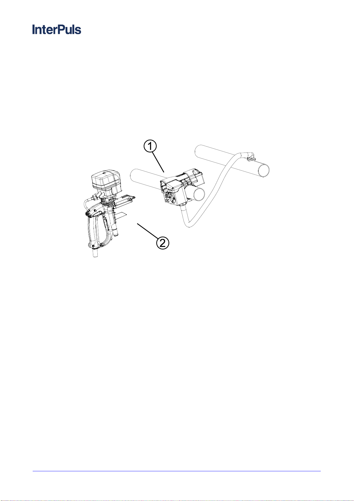
CombiFast®is a connecting system designed to simultaneously connect milk, vacuum, electrical power
supply and data transfer lines.
It is made of light, shock absorbent thermoplastic and features a practical handle which makes it easy to
transport and use.
Combifast®consists of a fixed part (rif. 1), assembled on the milk line, and a mobile one (rif. 2).
Combifast is available in different versions:
With milk and vacuum connectors.
With milk, vacuum and electrical power supply connectors.
With milk, vacuum, electrical power supply and data transfer connectors.
Suitable for use with air pulsator.
Suitable for use with electronic pulsator.
Combifast® - Instruction Manual, Operation and
Maintenance original instructions
1420066_02.17_EN
THIS MANUAL IS THE PROPERTY OF - InterPuls S.p.A. - ANY COPYING, EVEN PARTIAL, IS STRICTLY PROHIBITED
MI - 7
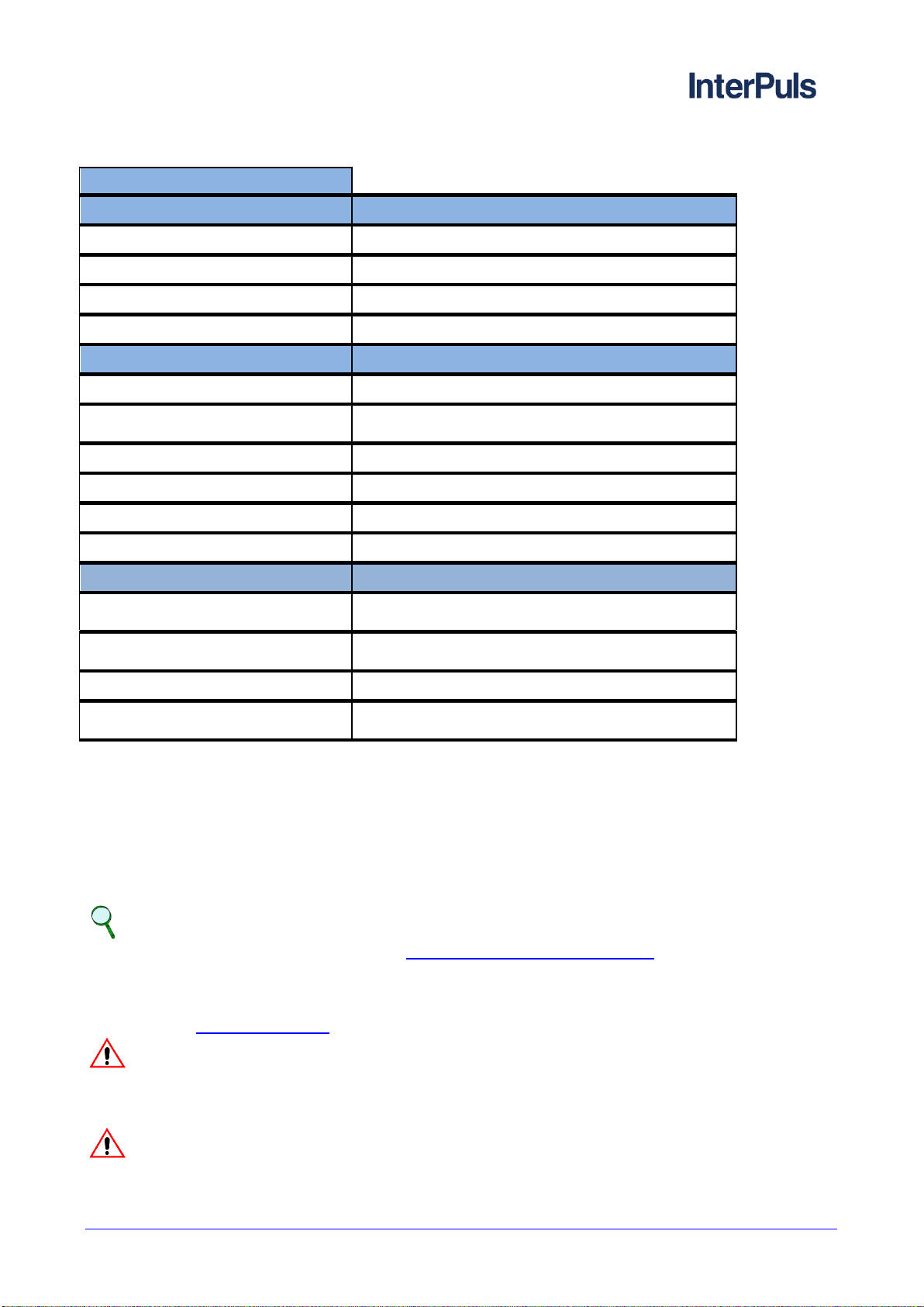
3 TECHNICAL FEATURES
Technical specifications
MOVABLE component
Milk Line (IDxOD)
16x18 mm (0.63x0.7 in)
Vacuum Line (IDxOD)
14x19 mm (0.55x0.74 in)
Dimensions (LxWxH)
240x240x89 mm (9.44x9.44x3.5 in)
Weight
0.146 Kg (0.32 lb)
FIXED component
Milk Line
OD 40 –50,8 –52 –63
Diameter stainless steel milk tube
opening
22 mm (0.86 in)
Diameter vacuum tube opening
22 mm (0.86 in)
Vacuum Connector (IDxOD)
14x19 mm (0.55x0.74 in)
Dimensions (LxWxH)
173 x 148 x 102 mm (6.81x5.82x4.01 in)
Weight
0.506 kg (1.11 lb)
Operation specifications
Operating vacuum
between 36 and 60kPa (typically 50kPa)
between 10.63 and 17.71 “Hg (typically 14.76 “Hg)
Operating temperatures
(environment)
-5ºC ÷ +40ºC (23°F ÷ 104°F)
Transport/storage temperatures
-20ºC ÷ +50ºC (-4°F ÷ 122°F)
Temperature of the washing
mixture
Min 60°C - Max 90°C (Min 140°F –Max 194°F)
4 FORESEEN AND UNFORESEEN USE
4.1 Foreseen use
CombiFast®is a connecting system designed to simultaneously connect milk, vacuum, electrical power
supply and data transfer lines.
Suitable for any round-the-shed milking system, CombiFast®can be used in conjunction with Portable
iMilk401, iMilk401 Lite and Acr Smart. They allow pulsation control, measurement of milk extracted (only with
Portable iMilk401 and iMilk401 Lite) and automatic cluster removal
NOTE
For further information see chapter 6 - COMBIFAST WITH PORTABLE.
4.2 Unforeseen use
The machinery, as outlined in this manual, must not be used for purposes other than those foreseen and
indicated in the 4.1 - Foreseen Use section.
WARNING
Any use other than the one covered in this manual is considered improper use and is
therefore forbidden. InterPuls S.p.A. declines any liability associated with any use of the
device other than the one covered in this manual.
WARNING
Application of loads is forbidden.

1420066_02.17_EN
Combifast® - Instruction Manual, Operation and Maintenance
original instructions
THIS MANUAL IS THE PROPERTY OF - InterPuls S.p.A. - ANY COPYING, EVEN PARTIAL, IS STRICTLY PROHIBITED
MI - 8
5 INSTALLATION
Step
Description
1
Foresee the installation of one fixed component for
every 2 animals.
Pierce the milk (ref. 3) and vacuum (ref. 4) lines
with a 22 mm (0.86 in) diameter drill bit.
CAUTION
Carefully sand the holes to avoid damaging the
gaskets.
Fig. 1 –Piercing and installation of lines
NOTE
Foresee one movable component
for every 5 fixed components.
Fig. 2 –Layout example
Combifast® - Instruction Manual, Operation and
Maintenance original instructions
1420066_02.17_EN
THIS MANUAL IS THE PROPERTY OF - InterPuls S.p.A. - ANY COPYING, EVEN PARTIAL, IS STRICTLY PROHIBITED
MI - 9
Step
Description
2
Install the fixed component on the milk line by
twisting the pair of screws (ref. 5) to the end;
carefully tighten the nut (ref. 6) located on the lower
half-shell to fully fasten.
CAUTION
To not over tighten the nut (ref. 6).
For optimal fastening, fully twist the nut once
after contact with the milk tube.
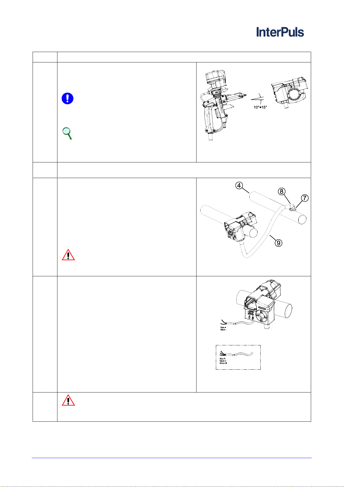
NOTE
In order to facilitate the installation, it is
suggested that the movable component be put
at an angle of 10 ~ 15° to the horizontal surface.
Fig. 3 –Suggested angle for fixed
components
3
Install the gasket (ref. 7) onto the vacuum line (ref. 4) and therefore, subsequently, the vacuum
withdrawal nipple (ref. 8) at a 90° angle.
4
Connect the fixed component to the vacuum nipple
(ref. 8) with the piece of tube (ref. 9). The length of
this piece must be adapted, in order to avoid harsh
curves or the partial twisting of the tube on itself.
Connect the claw’s milk tube to the Combifast’s
movable component ID 14 milk tube using a
suitable piece of milk tube (2.5m –8.2 ft
suggested).
Connect the pulsator to the claw with an equivalent
pulsator tube.
WARNING
The tube (ref. 9) must be positioned at a
distance from the animals.
Fig. 4 –Connection of fixed component to
the vacuum nipple
5
For systems which foresee milking with LP20 /
LP30 electronic pulsators, the fixed component’s
power supply must be connected to the IT
transformer.
Fig. 5 –Connection of pulsator’s power
supply / data transfer lines to the IT
junction box
6
WARNING
For the electrical version, verify that the connection of the cable to the main line is
perfectly isolated from the surrounding environment.
1420066_02.17_EN
Combifast® - Instruction Manual, Operation and Maintenance
original instructions
THIS MANUAL IS THE PROPERTY OF - InterPuls S.p.A. - ANY COPYING, EVEN PARTIAL, IS STRICTLY PROHIBITED
MI - 10
5.1 Operations for milking
Milking with Combifast is carried out as follows:
Step
Description
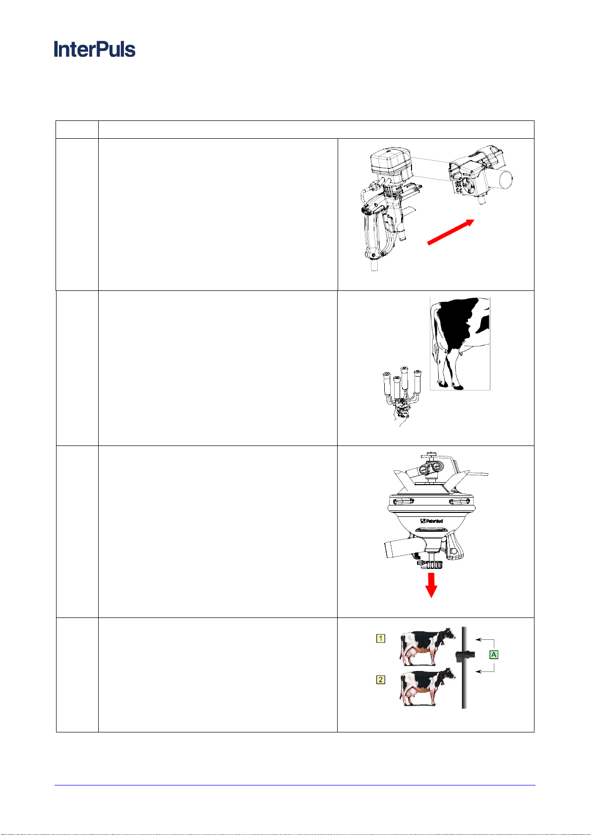
1
Insert the movable component in the fixed
component angled horizontally to facilitate insertion.
Fig. 1 –Insertion movable component
2
Attach the milking cluster to the animal (1) and
begin milking.
Fig. 2 –Application of milking cluster
3
Upon termination of milking, close the milking claw
valve and remove the cluster from the animal (1).
Fig. 3 –Valve closure
4
Open the claw valve and attach the cluster to the
next animal (2).
Milk the animal (2).
Upon termination of milking, close the milking claw
valve and remove the cluster from the animal.
Fig. 4 –Milking 1 and 2

Combifast® - Instruction Manual, Operation and
Maintenance original instructions
1420066_02.17_EN
THIS MANUAL IS THE PROPERTY OF - InterPuls S.p.A. - ANY COPYING, EVEN PARTIAL, IS STRICTLY PROHIBITED
MI - 11
Step
Description
5
Remove the movable component
from the first fixed component (A)
and insert it into the subsequent fixed
component (B).
Continue with the milking of animals
3 and 4.
Fig. 5 –Milking 3 and 4
6 COMBIFAST WITH PORTABLE
As shown in the following diagrams, CombiFast®can be connected to Portable iMilk401, oMilk401 Lite and
Acr Smart.
NOTE
For further details of use relating to Portable iMilk401, iMilk401 Lite and Acr Smart refer to the
relevant manuals.
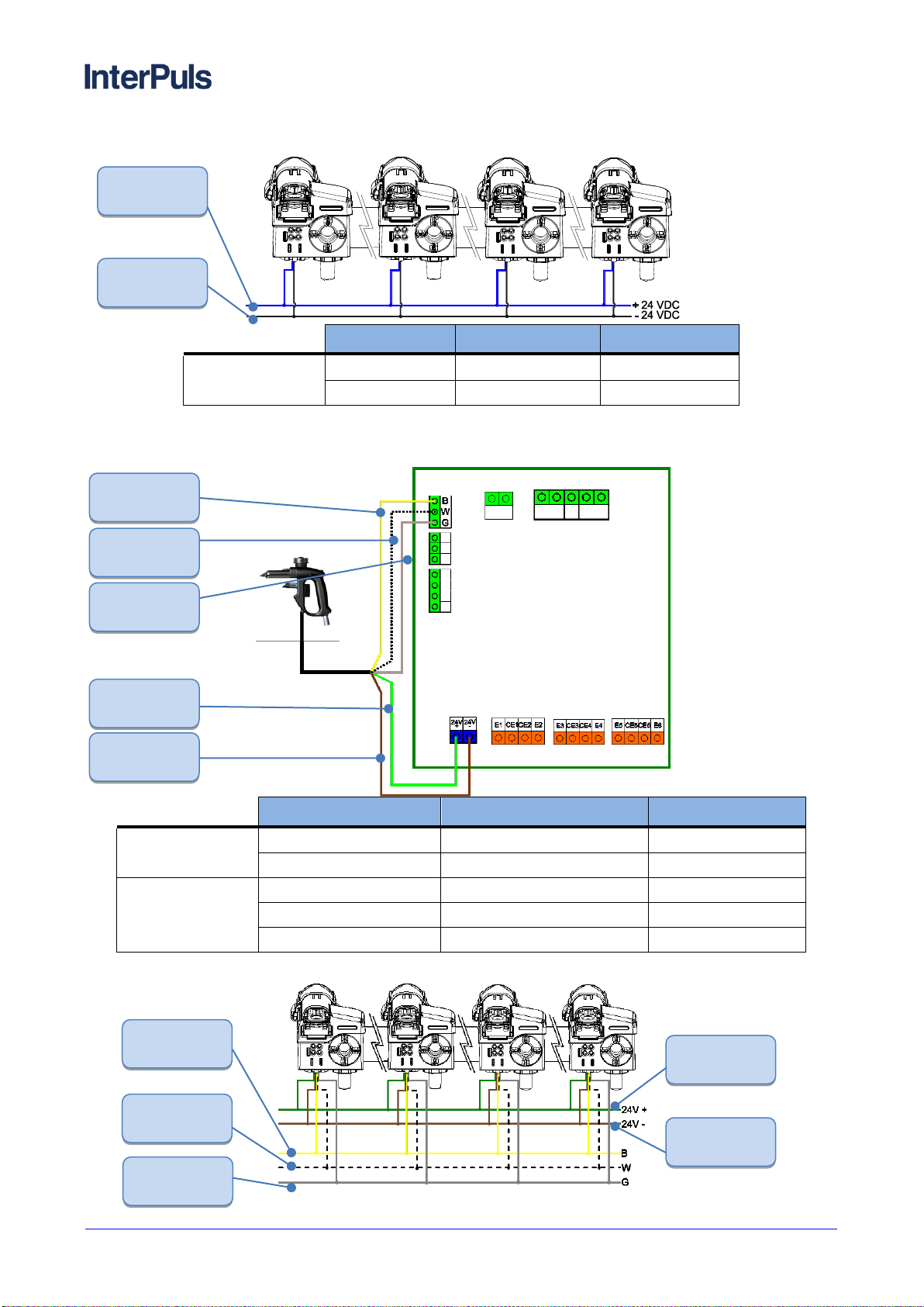
6.1 Combifast with Portable iMilk401 and Portable iMilk401 Lite
6.1.1 Connection without data download
6.1.1.1 Movable part
Terminal
Description
Cable Colour
POWER SUPPLY
SUPP.
24V +
BLUE
SUPP.
24V -
BLACK
BLUE
BLACK
1420066_02.17_EN
Combifast® - Instruction Manual, Operation and Maintenance
original instructions
THIS MANUAL IS THE PROPERTY OF - InterPuls S.p.A. - ANY COPYING, EVEN PARTIAL, IS STRICTLY PROHIBITED
MI - 12
6.1.1.2 Fixed Part
Terminal
Description
Cable Colour
POWER SUPPLY
SUPP.
24V +
BLUE
SUPP.
24V -
BLACK
6.1.2 Connection with data download
6.1.2.1 Movable Part
Terminal
Description
Cable Color
POWER SUPPLY
+24VDC
24VDC POWER SUPPLY
GREEN
-24VDC
CAN BUS
BROWN
CAN BUS
B
DATA DOWNLOAD
YELLOW
W
DATA DOWNLOAD
WHITE
G
DATA DOWNLOAD
SCREEN
6.1.2.2 Fixed Part
BLUE
BLACK
BROWN
WHITE
YELLOW
GREEN
SCREEN
GREEN
YELLOW
BROWN
WHITE
SCREEN

Combifast® - Instruction Manual, Operation and
Maintenance original instructions
1420066_02.17_EN
THIS MANUAL IS THE PROPERTY OF - InterPuls S.p.A. - ANY COPYING, EVEN PARTIAL, IS STRICTLY PROHIBITED
MI - 13
Terminal
Description
Cable Colour
POWER SUPPLY
+24VDC
SUPP.
GREEN
-24VDC
SUPP.
BROWN
SUPPLY
B
DATA DOWNLOAD
YELLOW
W
DATA DOWNLOAD
WHITE
G
DATA DOWNLOAD
SCREEN
6.2 Combifast with Portable Acr Smart
CN2 Terminal
Description
Cable Colour
POWER SUPPLY
1
24VDC (+)
BLUE
2
24VDC (-)
BLACK
GLOBE
3
GLOBE
BLUE
4
BLACK
CN1 Terminal
Description
Cable Colour
LE30
PULSATOR
9
Rear Pulsations
BLUE
10
Common
BLACK
11
Front Pulsations
BROWN
LE30
CONTROL
VALVE
12
Shut-off Valve
BLUE
13
CV20 Common
BLACK
14
DVC 1000
BROWN
SENSOR
15
HFS SENSOR
BLUE
16
BLACK
BLUE
BLACK
BROWN
BLUE
BLUE
BLUE
BLUE
BLACK
BLACK
BLACK
BLACK
1420066_02.17_EN
Combifast® - Instruction Manual, Operation and Maintenance
original instructions
THIS MANUAL IS THE PROPERTY OF - InterPuls S.p.A. - ANY COPYING, EVEN PARTIAL, IS STRICTLY PROHIBITED
MI - 14
7 MAINTENANCE
7.1 Daily maintenance
The product must be washed after every milking session:
Fixed component:
The areas of milk flow within the fixed component are automatically washed after every milking
session, when the system’s washing program is activated.
Movable component:
Every movable component is placed in the washing room on special fixed ledges dedicated to the
washing and stocking of the product until the following milking session.
7.2 Periodical maintenance
Combifast requires the following maintenance interventions on an annual basis:
Check the tightness of nut and screws:
- Check that the fastening nut and screws are correctly tightened.
Fig. 1 –Tightening of screws
External cleaning:
- Insert the movable component in the fixed component.
- Clean using a stream of room temperature water.
- Upon completion of the washing program, remove the
movable component from the fixed component.
Fig. 2 –External cleaning
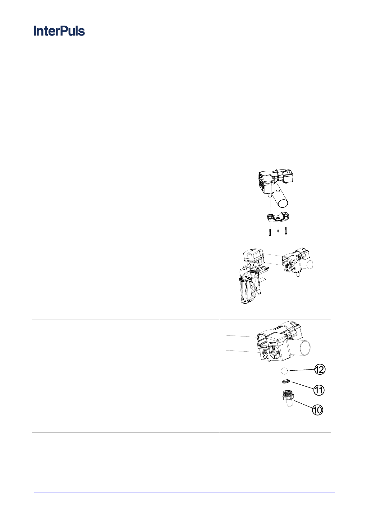
Periodic cleaning of compartment containing the vacuum
float ball:
- Disconnect the vacuum line from the straight nipple (ref. 10).
- Unscrew the straight nipple (ref. 10) avoiding that the black
gasket (ref. 11) and vacuum float ball (ref. 12) fall.
- Clean the compartment containing the vacuum float ball and the
edge of the gasket, where the ball sits, with warm water and a
neutral detergent.
- Carefully dry the components and insert the gasket (ref. 11)
onto the apposite part of the straight nipple (ref. 10), until
connected.
- Rest the ball (ref. 12) on the nipple complete with gasket.
- Tighten all components.
- Reconnect the vacuum line.
Fig. 3 –Cleaning of compartment
containing vacuum float ball
Check the tightness of the nipple (ref. 10):
Ensure the nipple (ref. 10) is screwed in.
This verification is vital to avoid the breaking of the movable component’s nipple.
Combifast® - Instruction Manual, Operation and
Maintenance original instructions
1420066_02.17_EN
THIS MANUAL IS THE PROPERTY OF - InterPuls S.p.A. - ANY COPYING, EVEN PARTIAL, IS STRICTLY PROHIBITED
MI - 15
8 TROUBLE SHOOTING
PROBLEM
DETECTED
POSSIBLE
CAUSE
SOLUTION
Problems
interesting the
movable
component
Incorrect
positioning of the
ball (ref 12, see
figure previous
page) ) in the
fixed component
Position the ball as indicated in the 7.2 - Periodical maintenance
section of this manual.
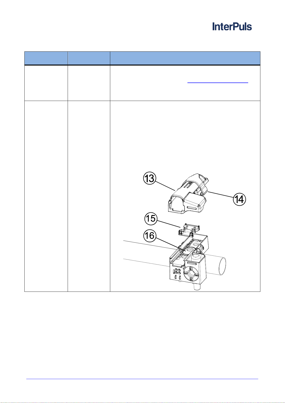
Problems
interesting /
removing of fixed
/ movable
component
Poor lubrication
upper surface of
milk gasket
Lubricate the sliding surface of the fixed component ‘s rectangular
drawer with vaseline oil or silicone spray as detailed below:
Dismantle the hood (ref. 13) by sliding the attached slider
(ref. 14).
Extract the rectangular drawer complete with steel spring
(ref 15).
Lubricate the upper surface (ref. 16) of the milk gasket in
contact with the drawer with a small quantity of vaseline oil
or silicone spray.
Reposition the drawer (ref. 15).
Reposition the hood (ref. 13) blocking it with the slider (ref.
14).

1420066_02.17_EN
Combifast® - Instruction Manual, Operation and Maintenance
original instructions
THIS MANUAL IS THE PROPERTY OF - InterPuls S.p.A. - ANY COPYING, EVEN PARTIAL, IS STRICTLY PROHIBITED
MI - 16
9 SPARE PARTS DIAGRAM
Table of contents
Other InterPuls Farm Equipment manuals


Popular Farm Equipment manuals by other brands


MacDon
MacDon FlexDraper FD2 Series installation instructions

Alamo
Alamo Bush Hog AGR Series Operator's manual

LMC
LMC RXT Series Operator's manual

Finn
Finn HydroSeeder T75 Operator Instructions And Parts Manual

Sulky
Sulky Tramline CE 300 Original instructions

Cumberland
Cumberland PNEG-240 Installation and operation manual