MacDon FlexDraper FD2 Series User manual

FD2 Series
FlexDraper®Header for Combines
Steel Finger Kits (MD #311054, 311055, 311068, and 311069)
Installation Instructions
215505 Revision A
Original Instruction
Featuring MacDon FLEX-FLOAT Technology®
The Harvesting Specialists.

FD2 Series FlexDraper®Header
Published March 2021
© 2021 MacDon Industries, Ltd.
The information in this publication is based on the information available and in effect at the time of printing. MacDon
Industries, Ltd. makes no representation or warranty of any kind, whether expressed or implied, with respect to the
information in this publication. MacDon Industries, Ltd. reserves the right to make changes at any time without notice.

Introduction
This document explains where to install the different steel fingers in the correct locations for FD230 and FD235 headers. A
list of parts included in each kit is provided in Chapter 2 Parts List, page 5.
Installation time
Installation time for this kit is approximately 3 hours.
Conventions
The following conventions are used in this document:
•Right and left are determined from the operator’s position. The front of the header is the side that faces the crop; the
back of the header is the side that connects to the combine.
•Unless otherwise noted, use the standard torque values provided in the header operator’s manual and technical
manual.
NOTE:
This document is currently available in English only.
215505 iRevision A


215505 iii Revision A
Introduction ................................................................................................................................................i
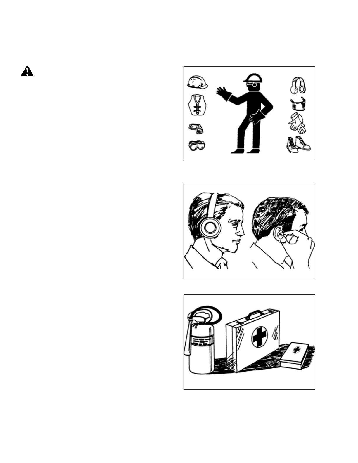
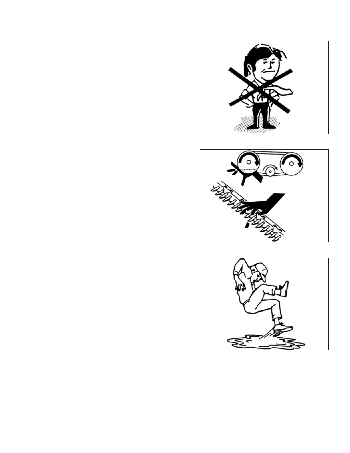
Chapter 1: Safety ........................................................................................................................................ 1
1.1 Signal Words .........................................................................................................................................1
1.2 General Safety .......................................................................................................................................2
Chapter 2: Parts List.................................................................................................................................... 5
2.1 Steel Finger Kit MD #311054 (FD230, Double Reel, Five Bats) .........................................................................5
2.2 Steel Finger Kit MD #311055 (FD230, Double Reel, Six Bats)...........................................................................6
2.3 Steel Finger Kit MD #311068 (FD235, Double Reel, Five Bats) .........................................................................7
2.4 Steel Finger Kit MD #311069 (FD235, Double Reel, Six Bats)...........................................................................8
Chapter 3: Steel Finger Placement............................................................................................................. 9
3.1 FD230, Double Reel, Five and Six Bats –Narrow......................................................................................... 10
3.2 FD230, Double Reel, Five and Six Bats –Wide............................................................................................ 11
3.3 FD235, Double Reel, Five and Six Bats –Narrow......................................................................................... 12
3.4 FD235, Double Reel, Five and Six Bats –Wide............................................................................................ 13
Chapter 4: Removing Existing Fingers and Bushings............................................................................... 15
4.1 Removing Bushings and Steel or Plastic Fingers from Reels .......................................................................... 15
Chapter 5: Installation Instructions ......................................................................................................... 25
5.1 Installing Bushings and Steel Fingers to Reels ............................................................................................ 25
5.2 Installing Reel Endshields ....................................................................................................................... 33
5.2.1 Installing Reel Endshields at Outboard Cam End ................................................................................ 34
5.2.2 Installing Reel Endshields at Inboard Tail End .................................................................................... 39
5.2.3 Installing Reel Endshields at Inboard Cam End................................................................................... 43
5.2.4 Installing Reel Endshields at Outboard Tail End ................................................................................. 48
TABLE OF CONTENTS


215505 1Revision A
Chapter 1: Safety
Understanding and following safety procedures consistently will help to ensure the safety of machine operators and
bystanders.
1.1 Signal Words
Three signal words, DANGER,WARNING, and CAUTION, are used to alert you to hazardous situations. Two signal words,
IMPORTANT and NOTE, identify non-safety related information.
Signal words are selected using the following guidelines:
DANGER
Indicates an imminently hazardous situation that, if not avoided, will result in death or serious injury.
WARNING
Indicates a potentially hazardous situation that, if not avoided, could result in death or serious injury. It may also be
used to alert against unsafe practices.
CAUTION
Indicates a potentially hazardous situation that, if not avoided, may result in minor or moderate injury. It may be used
to alert against unsafe practices.
IMPORTANT:
Indicates a situation that, if not avoided, could result in a malfunction or damage to the machine.
NOTE:
Provides additional information or advice.

215505 2Revision A
1.2 General Safety
Protect yourself when assembling, operating, and servicing machinery.
Figure 1.1: Safety Equipment
CAUTION
The following general farm safety precautions should be part of
your operating procedure for all types of machinery.
Wear all protective clothing and personal safety devices that
could be necessary for the job at hand. Do NOT take chances.
You may need the following:
•Hard hat
•Protective footwear with slip-resistant soles
•Protective glasses or goggles
•Heavy gloves
•Wet weather gear
•Respirator or filter mask
Figure 1.2: Safety Equipment
In addition, take the following precautions:
•Be aware that exposure to loud noises can cause hearing
impairment or loss. Wear suitable hearing protection devices
such as earmuffs or earplugs to help protect against loud
noises.
Figure 1.3: Safety Equipment
•Provide a first aid kit in case of emergencies.
•Keep a properly maintained fire extinguisher on the machine.
Be familiar with its proper use.
•Keep young children away from machinery at all times.
•Be aware that accidents often happen when the Operator is
tired or in a hurry. Take time to consider the safest way.
NEVER ignore warning signs of fatigue.
SAFETY

215505 3Revision A
Figure 1.4: Safety around Equipment
•Wear close-fitting clothing and cover long hair. NEVER wear
dangling items such as scarves or bracelets.
•Keep all shields in place. NEVER alter or remove safety
equipment. Make sure driveline guards can rotate
independently of shaft and can telescope freely.
•Use only service and repair parts made or approved by
equipment manufacturer. Substituted parts may not meet
strength, design, or safety requirements.
Figure 1.5: Safety around Equipment
•Keep hands, feet, clothing, and hair away from moving parts.
NEVER attempt to clear obstructions or objects from a
machine while the engine is running.
•Do NOT modify the machine. Unauthorized modifications
may impair machine function and/or safety. It may also
shorten the machine’s life.
•To avoid injury or death from unexpected startup of the
machine, ALWAYS stop the engine and remove the key from
the ignition before leaving the operator’s seat for any reason.
Figure 1.6: Safety around Equipment
•Keep service area clean and dry. Wet and/or oily floors are
slippery. Wet spots can be dangerous when working with
electrical equipment. Be sure all electrical outlets and tools
are properly grounded.
•Keep work area well lit.
•Keep machinery clean. Straw and chaff on a hot engine are
fire hazards. Do NOT allow oil or grease to accumulate on
service platforms, ladders, or controls. Clean machines before
storage.
•NEVER use gasoline, naphtha, or any volatile material for
cleaning purposes. These materials may be toxic and/or
flammable.
•When storing machinery, cover sharp or extending
components to prevent injury from accidental contact.
SAFETY


215505 5Revision A
Chapter 2: Parts List
A parts list is provided in this instruction so that you can confirm that you have received all required parts before you begin
installation.
2.1 Steel Finger Kit MD #311054 (FD230, Double Reel, Five Bats)
$
%
&
'
(
Ref
Part
Number Description Quantity
1311324 FINGER –LH SINGLE CONCENTRIC 10
2 311323 FINGER –RH SINGLE CONCENTRIC 4
3 311322 FINGER –TAIL END INBOARD 5
4311321 FINGER –TAIL END OUTBOARD 5
5137092 FINGER 135
6 220941 CLAMP –TINE TUBE BUSHING, CENTER RIB (BOX OF 5) 6
7273052 RETAINER –END FINGER 10
A108172 BOLT –HEX HD M10 X 1.5 X 65-8.8-AA1J 10
B184584 WASHER –CON SPRING M10 STL SAE 10
C135800 NUT –HEX CTR LOC SPCL M10 X 1.5-9-AA1J 10
D137118 BOLT –BTN HD RIB NK 3/8 NC 149
E30228 NUT –FLG DT SM FACE 3/8-16 UNC-GR5-AA1J 149

215505 6Revision A
2.2 Steel Finger Kit MD #311055 (FD230, Double Reel, Six Bats)
$
%
&
'
(
Ref
Part
Number Description Quantity
1311324 FINGER –LH SINGLE CONCENTRIC 12
2 311323 FINGER –RH SINGLE CONCENTRIC 6
3 311322 FINGER –TAIL END INBOARD 6
4311321 FINGER –TAIL END OUTBOARD 6
5137092 FINGER 135
6 220941 CLAMP –TINE TUBE BUSHING, CENTER RIB (BOX OF 5) 8
7273052 RETAINER –END FINGER 12
A108172 BOLT –HEX HD M10 X 1.5 X 65-8.8-AA1J 12
B184584 WASHER –CON SPRING M10 STL SAE 12
C 135800 NUT –HEX CTR LOC SPCL M10 X 1.5-9-AA1J 12
D137118 BOLT –BTN HD RIB NK 3/8 NC 153
E30228 NUT –FLG DT SM FACE 3/8-16 UNC-GR5-AA1J 153
PARTS LIST

215505 7Revision A
2.3 Steel Finger Kit MD #311068 (FD235, Double Reel, Five Bats)
$
%
&
'
(
Ref
Part
Number Description Quantity
1311324 FINGER –LH SINGLE CONCENTRIC 30
2 311323 FINGER –RH SINGLE CONCENTRIC 18
3 311322 FINGER –TAIL END INBOARD 5
4311321 FINGER –TAIL END OUTBOARD 5
5137092 FINGER 143
6 220941 CLAMP –TINE TUBE BUSHING, CENTER RIB (BOX OF 5) 8
7273052 RETAINER –END FINGER 10
A108172 BOLT –HEX HD M10 X 1.5 X 65-8.8-AA1J 10
B184584 WASHER –CON SPRING M10 STL SAE 10
C 135800 NUT –HEX CTR LOC SPCL M10 X 1.5-9-AA1J 10
D137118 BOLT –BTN HD RIB NK 3/8 NC 191
E30228 NUT –FLG DT SM FACE 3/8-16 UNC-GR5-AA1J 191
PARTS LIST

215505 8Revision A
2.4 Steel Finger Kit MD #311069 (FD235, Double Reel, Six Bats)
$
%
&
'
(
Ref
Part
Number Description Quantity
1311324 FINGER –LH SINGLE CONCENTRIC 36
2 311323 FINGER –RH SINGLE CONCENTRIC 24
3 311322 FINGER –TAIL END INBOARD 6
4311321 FINGER –TAIL END OUTBOARD 6
5137092 FINGER 171
6 220941 CLAMP –TINE TUBE BUSHING, CENTER RIB (BOX OF 5) 10
7273052 RETAINER –END FINGER 12
A108172 BOLT –HEX HD M10 X 1.5 X 65-8.8-AA1J 12
B184584 WASHER –CON SPRING M10 STL SAE 12
C 135800 NUT –HEX CTR LOC SPCL M10 X 1.5-9-AA1J 12
D137118 BOLT –BTN HD RIB NK 3/8 NC 231
E30228 NUT –FLG DT SM FACE 3/8-16 UNC-GR5-AA1J 231
PARTS LIST

215505 9Revision A
Chapter 3: Steel Finger Placement
Refer to the following illustrations during the installation process to make sure the fingers are placed in the correct
locations for your application:
•3.1 FD230, Double Reel, Five and Six Bats –Narrow, page 10
•3.2 FD230, Double Reel, Five and Six Bats –Wide, page 11
•3.3 FD235, Double Reel, Five and Six Bats –Narrow, page 12
•3.4 FD235, Double Reel, Five and Six Bats –Wide, page 13

215505 10 Revision A
3.1 FD230, Double Reel, Five and Six Bats –Narrow
$
%
&
'
(
Figure 3.1: Left Side Narrow
1 - MD #137092 2 - MD #311321 3 - MD #220941 4 - MD #273052
A - MD #108172 B - MD #184584 C - MD #135800 D - MD #137118 E - MD #30228
$
%
$
%
Figure 3.2: Right Side Narrow
1 - MD #137092 2 - MD #311324 3 - MD #220941 A - MD #137118 B - MD #30228

215505 11 Revision A
3.2 FD230, Double Reel, Five and Six Bats –Wide
$
%
&
'
(
'
(
Figure 3.3: Left Side Wide
1 - MD #137092 2 - MD #311321 3 - MD #311323 4 - MD #220941 5 - MD #273052
A - MD #108172 B - MD #184584 C - MD #135800 D - MD #137118 E - MD #30228
$
%
$
%
$
%
Figure 3.4: Right Side Wide
1 - MD #137092 2 - MD #311324 3 - MD #311323 4 - MD #220941 A - MD #137118 B - MD #30228
STEEL FINGER PLACEMENT

215505 12 Revision A
3.3 FD235, Double Reel, Five and Six Bats –Narrow
$
%
&
'
(
'
(
'
(
Figure 3.5: Left Side Narrow
1 - MD #137092 2 - MD #311321 3 - MD #311324 4 - MD #311323 5 - MD #220941 6 - MD #273052
A - MD #108172 B - MD #184584 C - MD #135800 D - MD #137118 E - MD #30228
$
%
$
%
$
%
Figure 3.6: Right Side Narrow
1 - MD #137092 2 - MD #311324 3 - MD #311323 4 - MD #220941 A - MD #137118 B - MD #30228
STEEL FINGER PLACEMENT

215505 13 Revision A
3.4 FD235, Double Reel, Five and Six Bats –Wide
$
%
&
'
(
'
(
'
(
Figure 3.7: Left Side Wide
1 - MD #137092 2 - MD #311321 3 - MD #311324 4 - MD #311323 5 - MD #220941 6 - MD #273052
A - MD #108172 B - MD #184584 C - MD #135800 D - MD #137118 E - MD #30228
$
%
$
%
$
%
Figure 3.8: Right Side Wide
1 - MD #137092 2 - MD #311324 3 - MD #311323 4 - MD #220941 A - MD #137118 B - MD #30228
STEEL FINGER PLACEMENT

Other manuals for FlexDraper FD2 Series
4
This manual suits for next models
2
Table of contents
Other MacDon Farm Equipment manuals

MacDon
MacDon D1X Series User manual

MacDon
MacDon FlexDraper FD1 Series User manual

MacDon
MacDon M155 User manual

MacDon
MacDon D1X Series User manual

MacDon
MacDon FlexDraper FD1 Series User manual

MacDon
MacDon D65 User manual

MacDon
MacDon FlexDraper FD1 Series User manual

MacDon
MacDon M1 Series User manual

MacDon
MacDon HC10 Guide

MacDon
MacDon 5020 User manual