FERPINTA Herculano S1ET User manual
// OPERATOR’S MANUAL
S1ET
EN

ÍNDEX
INTRODUCTION____________________________________________
GENERAL MODEL IDENTIFICATION___________________________
EQUIPEMENT IDENTIFICATION______________________
AXLE IDENTIFICATION _____________________________
SIMBOLOGY_______________________________________________
EC” DECLARATION OF CONFORMITY _______________
SAFETY ALERTS ____________________________________
GENERAL SAFETY RULES_____________________________________
SAFETY____________________________________________________
WARNING LABELS POSITION ________________________________
TECHNICAL SPECIFICATION_________________________________
INITIAL COUPLING TO TRAILER_______________________________
HYDRAULIC SYSTEMS_______________________________________
HYDRAULIC SYSTEM CONNECTIONS ________________
HYDRAULIC DRAWBAR_____________________________
TIPPING SYSTEM___________________________________
HYDRAULIC BRAKING SYSTEM______________________
PNEUMATIC BRAKING SYSTEM_______________________________
ELETRICAL CONNECTION SYSTEM____________________________
SIGNALING AND LIGHTNING________________________________
PARKING / EMERGENCY BRAKE SYSTEM______________________
4
5
5
5
6
6
6
7
9
10
11
13
14
14
14
15
16
18
19
20
22
INERTIA BRAKING_______________________________________
STARTING WORK________________________________________
OPCIONALS____________________________________________
DEVICES TO PREVENT UNAUTHORIZED USE ________________
MAINTENANCE AND SERVICE____________________________
MAINTENANCE AND SERVICE (INERTIA SYST.)_____________
TIMETABLE - MAINTENANCE AND SERVICE________________
MALFUNTIONS / POSSIBLE SOLUTIONS____________________
EQUIPMENTS END OF LIFE________________________________
WARRANTY CONDITIONS________________________________
HOW TO ORDER PARTS__________________________________
23
26
27
28
29
34
38
40
41
42
43

OPERATOR’S MANUAL: S1ET
REV. 02.2022 4
INTRODUCTION
Dear Customer,
Congratulations on your choice, as you have just purchased equipment built with high technology and
strict quality standards.
All our efforts are put into research, innovation, development and improvement of this product, so that you
can take advantage of the quality, performance, and work in safety.
This manual was created to help you and to advise about safety, maintenance and how to use the
equipment. Thereby, you will be able to use it with confidence in order to ensure a good performance.
Please start by reading it carefully in order to become familiar with all the equipment and the most
important aspects of safety, its usage as well as other useful information.
Anyone operating, maintaining, or transporting this equipment must read and thoroughly understand the
instructions outlined in this manual before starting to work.
Please take note of all issues related to safety and instructions included in this manual, complying with them
in order to guarantee your safety and others safety.
Please keep the manual in an accessible and safe place, so that you can refer to it whenever necessary.
It is essential that this equipment is inspected periodically, that it is maintained and fitted with suitable spare
parts.
HERCULANO will provide you with any necessary support, solving problems or clarifying questions that you
may have when using the equipment.
HERCULANO –ALFAIAS AGRÍCOLAS S.A.
3720-051 Oliveira de Azeméis
PORTUGAL
OPERATOR’S MANUAL: S1ET
REV. 02.2022 5
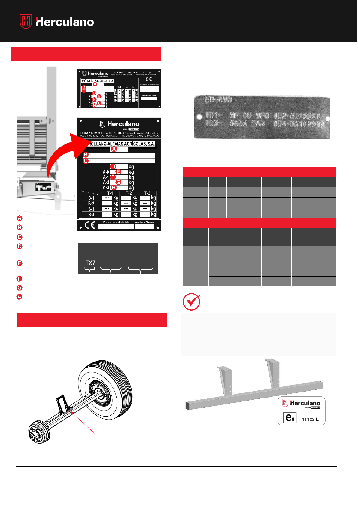
GENERAL MODEL IDENTIFICATION
•Improves safety in the event of an accident
•Minimizes the consequences of a rear-end
collisions;
•Prevents underride accidents of the rear-end of
vehicle;
HYDRAULIC | PNEUMATIC BRAKING
LABEL
ID1
ID2
ID3
ID4
EB/AMB
MF
250x60V
3198
36106218
EB/AMB
MF or
MFG
300x60V
5886
36102919
EB/AMB
FF
400x80V
7848
36103119
INERTIA BRAKING (30 KM/H OU 40KM/H)
AXLE
LABEL
TYPE
R (UE) 2015/68
HOMOLOGATION
NO.
300x60
FAD
3006R
361-054-16
ADR
306R
361-067-19
300x90
FAD
3009RA
361-007-20
ADR
309T
361-004-18
EQUIPMENT IDENTIFICATION
IDENTIFICATION NO.
ID TAG PLATE
TX7 0S1ET * * * * *
00S1ET
OR
WMI
Code
Vehicle
Id.
Serial
manufatur
e NO.
The information of the serial number and type of axle
is stamped on the identification plate located at the
following place:
AXLE IDENTIFICATION
Axle identification plate
The plates can be metallic or stickers. They enclose
important information as they identify the type of
axle and in case it is needed a repair or
replacement of parts.
Example of an (EB) axle identification sticker.
APROVED –UNDERRUN BAR
The trailer is equipped with homologated bumpers.
- Category
- Homologation No.
- Identification No.
- Maximum load
Technically allowable
- Load on the device
- Load on the 1st axle
- Load on the 2nd axle
- Load on the 3rd axle

OPERATOR’S MANUAL: S1ET
REV. 02.2022 6
SIMBOLOGY
EC DECLARATION OF CONFORMITY
This equipment complies with the requirements of the European Parliament and Council Directive,
2006/42/EC, of 17 May 2006, transposed into Portuguese law by Decree-Law No. 103/2008 of 24 June
2008.
The EC Declaration of Conformity is attached to the Trailer User Manual.
SAFETY ALERTS
DANGER!
Failure to comply with this signal may cause damage
to the equipment and cause serious injuries to people,
endangering your own life.
•
All "Danger" instructions must be followed and
respected!
WARNING!
If you do not respect this signal, you will be subject to
severe injuries and possible damage to the
equipment.
•
All "Warning" instructions must be followed
and respected!
INFORMATION
Additional useful information goes next these symbols!
•
Please read all the points with additional
information carefully since they are useful to
become familiar with your equipment.
CAUTION!
The special caution signals go next this symbol!
•
Please take the necessary precautions and
follow the recommended operating
instructions to avoid problems or accidents.
MAINTENANCE!
Iconography used for Maintenance and/ or Cleaning!
•
Carefully carry out the recommended
maintenance and cleaning procedures to extend
the equipment's service life and keeping the safety
conditions.
LUBRIFICATION!
The Lubrication and Oil Level Replacement
Instructions go next to this symbol!
•Please pay attention to the lubrication points and
periodicity, or the replacement of grease or oil
level. Failure to follow this instruction may
jeopardize the proper performance of the
equipment.

OPERATOR’S MANUAL: S1ET
REV. 02.2022 7
GENERAL SAFETY RULES
Changes to the Trailer:
The chassis structure, wheels, braking system, hydraulic/pneumatic system and electrical system must not be
modified or reconverted, as they are important safety elements and, if they are altered, they may jeopardize
the safety of the equipment.
•Before carrying out any maintenance or a repair
operation on the equipment that requires tipping,
make sure that the vehicle is properly stabilized
and on flat ground. Switch off the engine and
properly put the tractor’s brake on before
proceeding with any operation that may
jeopardize your safety and others' safety.
•Serious fatal errors can occur if precautions are
not taken and safety measures are not
respected.
•Equipment must only be repaired, and damaged
components only replaced, by certified or
qualified people for this purpose.
•Make sure that you carry out all inspections and
services on your equipment at specific time
ranges.
•Make sure that all spare parts and components
are compatible with the equipment and that
they do not affect the safety of the vehicle, your
safety, or others' safety.
•It is recommended that you always use original
replacement parts / spare parts from the
manufacturer to ensure that they fit properly and
that they do not affect the vehicle’s structural
capacity or safety.
•Whenever carrying out coupling / decoupling of
the equipment, it is strictly forbidden to stand
between the tractor and trailer unless they are
properly immobilized with the parking brake on, if
applicable, and with wheel chocks.

OPERATOR’S MANUAL: S1ET
REV. 02.2022 8
GENERAL SAFETY RULES
•When it is necessary to couple the trailer to the
tractor, please stand in one side of the tractor
and make sure that you properly fit the safety
pins or chains.
•Always wear suitable clothes and shoes,
avoiding the use of loose or baggy clothing.
•Never carry out maintenance work with the
trailer tipped without first installing the safety
prop between the upper frame and the lower
frame.
•Do not allow people to remain or ride in the
trailer.
•Always check the pressure and general
condition of the trailer's and tractor's tires prior
to each use.
•The equipment's legal load limits must not be
exceeded;
•Always comply with your tractor’s towing load
limits.
•Regularly check the general condition of the
hydraulic and pneumatics hoses, if applicable.
Replace them in case they are damaged or worn
out. Replacement hoses must meet the technical
requirements specified by the manufacturer.
•Check oil levels regularly and keep the lubrication
points properly lubricated with grease and check
if they are not dirty.
•Before starting transportation, check if the braking
system is working properly.
•When driving on public roads, comply with the
rules in force. Always check if the lightning devices
fitted to the rear, side, and front of the vehicle,
work correctly.
•Depending on the characteristics of the
equipment and the type of product loaded, the
total weight of the vehicle under full load may
exceed the Maximum Allowable Mass regulated
in the country in which it travels. In the case of
traffic on public roads, the user must ensure
compliance with the dimensions and masses
defined in the legislation and highway code
applicable in the country. Herculano will not be
held responsible for any consequences arising
from non-compliance with legal requirements.

OPERATOR’S MANUAL: S1ET
REV. 02.2022 9
SAFETY
Danger of crushing!! Always attach the safety
prop!
7 AC 016
Danger of crushing!
Do not tipping on sloping terrain!
7 AC 017
Elevation points –Wheels
Change.
7 AC 137.1
PERSONAL PROTECTIVE EQUIPMENT
It is very important that the operator wears personal
protective equipment daily to minimize the risks of
an accident.
The instructions in this manual are essential, please
always use PPE's - Personal Protective Equipment.
PLEASE WEAR –PROTECTION FOOTWEAR
PLEASE WEAR –PROTECTION GLOVE
PLEASE WEAR –PROTECTION HELMET
PLEASE WEAR –PROTECTION VEST/CLOTHING
Warning stickers are part of the User Manual. Please
follow all procedures, keep the stickers legible and
immediately replace any lost or damaged labels
WARNING LABELS
Please always read the user manual!
7 AC 001
Danger! Articulated machine!
7 AC 004
Danger of crushing!
Tipping trailer!
7 AC 015
Danger of crushing!
Tipping rear door!
7 AC 018
7 AC 019
7 AC 018
7 AC 019
Produtct check - OK
7 AC 047
Tire pressure indicator. Inflation pressuer
varies depending on the fitted wheel!
7 AC 024
Side tipping alert.
7 AC 028
Lubrication point!!
7 AC 082
Indication off wheel and torque tightening!
7 AC 111
Danger of electric shock / eletrocution –overhead power
lines!
(When Applicable)
7 AC 119
Manual valve of the braking
system Min / MED / MAX
(When Applicable)
7 AC 124
Warning to adjust the manual valve of
the hydraulic braking system,
accordingly to the load transportation.
(When Applicable) 7 AC 124.1
Warning to adjust the rear door latches.
(If applicable)
7 AC 125
Warning for the depressurization valve
location!
(When Applicable)
7 AC 127
Matching timetable of the
Hydraulic Functions by colour.
7 AC 128
Warning!
Lubrication and Oil Change Periodicity
OPERATOR’S MANUAL: S1ET
REV. 02.2022 10
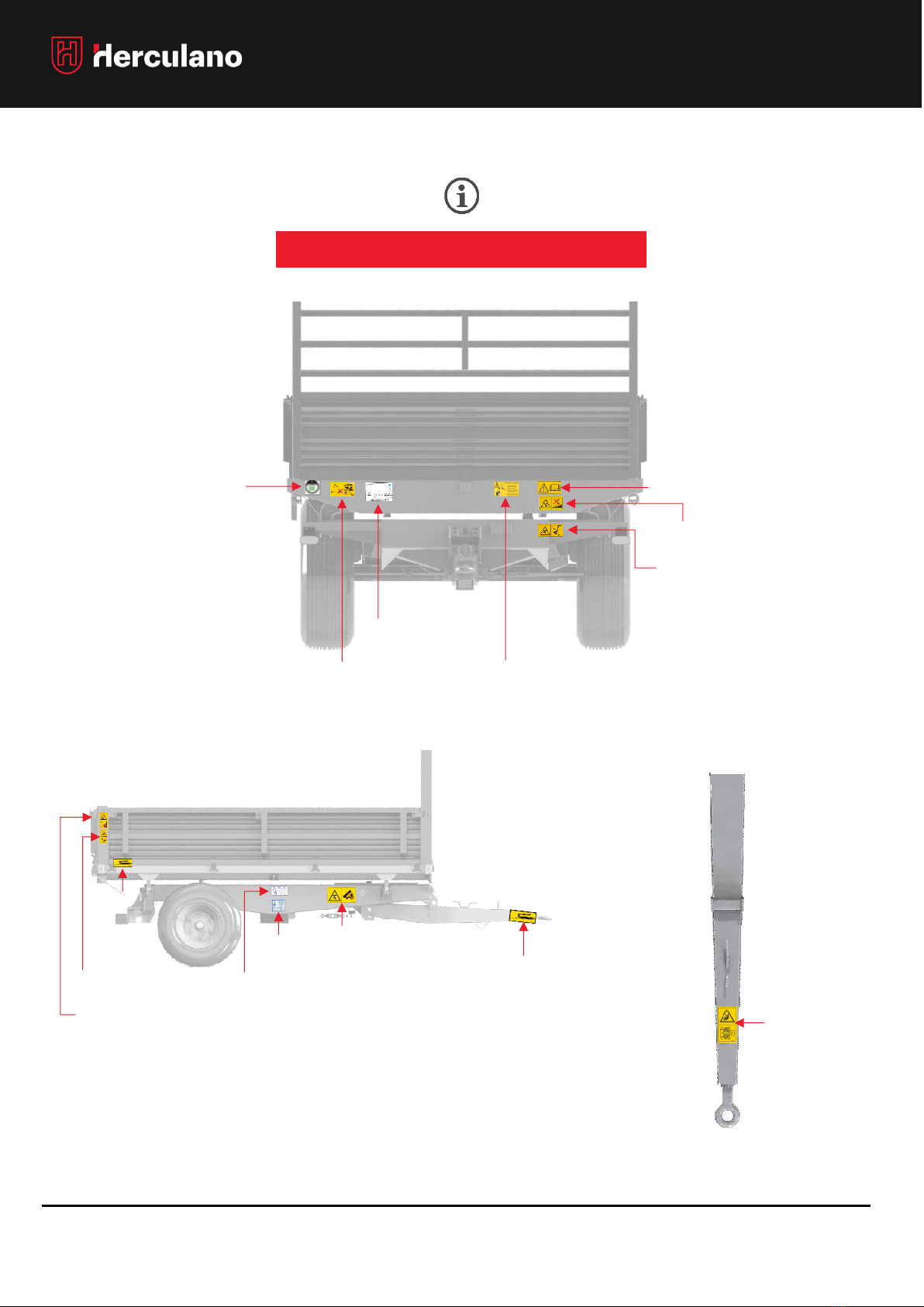
SAFETY
WARNING LABELS POSITION
7 AC 047
7 AC 028
7 AC 001
7 AC 017
7 AC 016
7 AC 124*
*WHEN APPLICABLE
7 AC 018*
7 AC 019*
7 AC 004
7 AC 082
7 AC 082
7 AC 024
7 AC 111
7 AC 015
OIL CHANGE
PERIODICITY

OPERATOR’S MANUAL: S1ET
REV. 02.2022 11
TECHNICAL SPECIFICATIONS
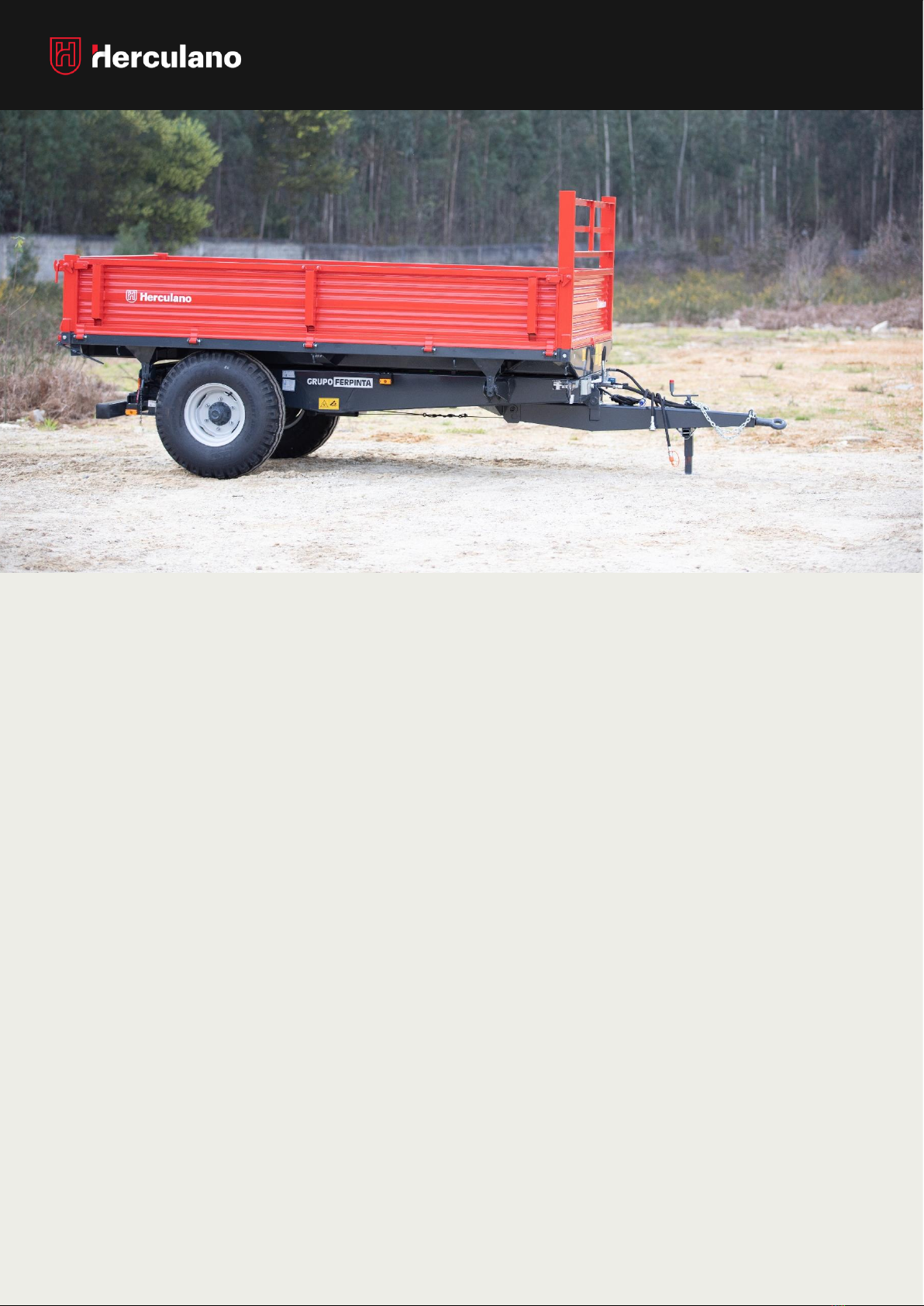
TIPPING SEMITRAILER - S1ET
BOX
DIMENSION
S1ET
2,25x1,40
S1ET
2,50x1,55
S1ET
2,70x1,55
S1ET
2,85x1,70
*
S1ET
3,00x1,60
*
S1ET
3,20x1,85
*
S1ET
3,50x1,90
*
S1ET
3,50x2,00
*
S1ET
3,80x2,00
*
S1ET
4,00x2,20
S1ET
4,60x2,30
S1ET
5,00x2,40
Box height –1
LEVEL (m)
0,5
0,5
0,5
0,5
0,5
0,5
0,5
0,5
0,5
0,5
0,5
0,5
Box height –2
LEVEL (m)
-
-
-
-
1,0
1,0
1,0
1,0
1,0
1,0
1,0
1,0
Box height –2
LEVEL (m)
-
-
-
-
1,5
1,5
1,5
1,5
1,5
1,5
1,5
1,5
Box Volume –1
LEVEL (0,5m) (m3)
-
-
-
-
2,0
2,2
3,1
3,3
3,6
4.1
5.0
5.7
Box Volume –2
LEVEL (1,0m) (m3)
-
-
-
-
4,0
4,2
6,2
6,6
7,2
8.2
10.0
11.4
Box Volume –3
LEVEL (1,5m) (m3)
-
-
-
-
6,0
6,4
9,3
9,9
10,8
12.3
15.0
17.1
Indicative Total
Wheight (t)
0.56
0.69
0.74
1.50
0.88
1.02
1.12
1.10
1.24
1.34
1.98
2.50
Internal Lenght –
BOX (mm)
2160
2410
2661
2760
2910
3110
3110
3700
3710
3910
4510
4910
Internal Width –
BOX (mm)
1310
1460
1510
1610
1510
1760
1760
1910
1910
2110
2210
2310
External Lenght –
BOX (mm)
2250
2500
2700
2850
3000
3200
3500
3500
3800
4000
4600
5000
External Width -
BOX (mm)
1400
1550
1550
1700
1600
1850
1850
2000
2000
2200
2300
2400
External Width -
BOX (mm)
3320
3560
3860
3975
4125
4530
4850
4870
5165
5390
6020
6370
Maximum Total
Width (mm)
1510
1670
1670
1810
1710
1950
1950
2060
2060
2300
2400
2500
S1ET TECHNICAL SPECIFICATIONS
STANDARD
THREE SIDE TIPPING, METALIC BOX
WHELLS S1ET 10,0/75-15.3 |11,5/80-15.3 | 12,5/80-15.3 |
435/50 R19,5 | 385/65 R22,5 (ACCORDING TO THE MODEL)
HEIGHT ADJUSTABLE DRAWBAR
FIXED AXLES
HYDRAULIC BRAKING
REMOVABLE FRONT MESH PROTECTION
ADJUSTABLE DRAWBAR SUPPORT
SECURITY AND LIGHTNING DEVICES
POSSIBILITY TO APPLY STANCHIONS
* INERTIA BRAKING OPTION
•The presented values refer only to “STANDARD”
models.
•Dimensions vary according to wheels applied.

OPERATOR’S MANUAL: S1ET
REV. 02.2022 12
TECHNICAL SPECIFICATIONS
TIPPING SEMITRAILER - S1ET
BOX
DIMENSION
S1ET
2,25x1,40
S1ET
2.50x1,55
S1ET
2.70x1,55
S1ET
2.85x1,70
*
S1ET
3,00x1.60
*
S1ET
3,20x1.85
*
S1ET
3,50x1.90
*
S1ET
3,50x2,00
*
S1ET
3,80x2,00
*
S1ET
4.00x2,20
S1ET
4.60x2,30
S1ET
5.00x2,40
Fully Tipped Height –
1LEVEL (mm)
2780
2850
3000
3120
3060
3460
3460
3630
3670
4180
4400
4710
Fully Tipped Height –
2LEVEL (mm)
-
-
-
-
3722
4048
3952
4075
4287
4457
4684
5116
Fully Tipped Height –
3LEVEL (mm)
-
-
-
-
4076
4418
4346
4428
4640
4828
5112
5499
Maximum
Drawbar
Load (Kg)
Hydraulic/
Pneumatic
Braking
1100
1100
1500
1500
1500
1500
1500
1500
1500
2000
3000
3000
Inertia
Braking
-
-
-
1000
1000
1000
1000
1000
1000
-
-
-
Hydraulic
Braking at
25km/h
1000
1000
1500
1500
1500
1500
1500
1500
1500
2000
2200
-
Tipping Cylinder –No. of
section
3
3
3
3
4
4
4
4
5
5
6
7
Tipping Cylinder –Ø
(mm)
110
110
110
110
130
130
130
130
193
150
170
193
Tipping Cylinder –Travel
(mm)
580
580
687
580
840
840
840
840
1491
1050
1237
1491
Tipping Cylinder –
Pressure (Bar)
180
180
180
180
180
180
180
180
180
180
180
180
Tipping Cylinder –Oil
Volume (L)
3
3
3
3
3,3
3,3
3,3
3,3
7,5
6,5
9,0
13,5
Tipping Angle - Rear (º)
44
40
39
38
45
42
38
38
45
42
38
42
Tipping Angle - Side (º)
45
45
45
45
45
45
45
45
45
45
45
45
Axle Track –STANDARD
(mm)
1200
1300
1300
1400
1300
1500
1600
1600
1600
1600
1700
1750
Axle Frame (mm)
50
60
60
60
60
70
70
70
70
80
90
9
Hub Brakes
250x60
300x60
300x60
300x60
300x60
300x60
300x60
300x60
300x60
300x60
400x80
400x80
No. of Bolts -Axle
6
6
6
6
6
6
6
6
6
6
8
8
* INERTIA BRAKING OPTION

OPERATOR’S MANUAL: S1ET
REV. 02.2022 13
TRAILER COUPLING TO TRACTOR
INITIAL TRACTOR COUPLING
NOTE: Before starting the coupling, make sure that the
trailer is on a level ground and that the parking brake
is properly on. If you have chocks, always make sure
that the trailer wheels are chocked before starting the
following procedures.
When you need to couple / uncouple the trailer to the
tractor, no one should be present in the area between
the two vehicles! This is considered a danger zone!
TRAILER COUPLING TO TRATOR
1º Align and move the tractor’s coupler towards the
coupler's device of the trailer’s drawbar.
2º Connect the drawbar’s safety chains to the
tractor;
3º Connect all trailer's hydraulic and pneumatic
hoses (if applicable) to the tractor's hydraulic
sockets;
Note: The tractor must be off;
4º Connect the plugs of the trailer electrical systems
to the tractor’s socket;
5º Operate the drawbar’s rest hydraulic cylinder in
order to level the coupling device with the
tractor’s coupler;
6º
6º Slowly move the tractor in reverse until it aligns
the tractor's coupler with the coupler's device
of the trailer’s drawbar. When they are properly
aligned, proceed to the coupling.
7º Make sure you have completed the previous
step correctly and retract the hydraulic cylinder
from the drawbar to the operating position;
8º Remove the chocks from the wheels (if fitted)
and proceed to work safely by releasing the
hand brake / parking brake.
! WARNING !
PEOPLE IN THE DANGER ZONE BETWEEN THE
TRACTOR AND THE TRAILER MAY BE CRUSHED OR
RUN OVER!
KEPP OUT ALL PEOPLE FROM THE DANGER ZONE WHEN TO
COUPLING / UNCOUPLING THE TRAILER;
NO ONE IS AUTHORIZED TO RAMAIN ALONGSIDE THE
TRAILER AXELS / TRATOR WHEN THEY ARE BEING COUPLED;
THE OPERATOR MUST ALLWAYAS KEEP WELL AWAY FROM
FRO THE VEHICLE WEELS.
OPERATOR’S MANUAL: S1ET
REV. 02.2022 14
HYDRAULIC SYSTEMS
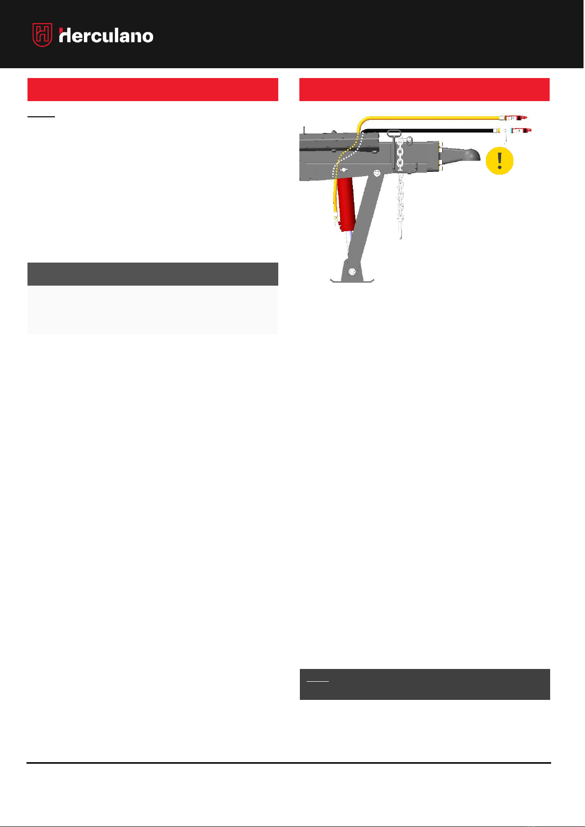
DRAWBAR REST
CONNECTION OF HYDRAULIC SYSTEMS
NOTE: For safety reasons, never connect or
disconnect the hydraulic systems while the box is
tipped! When connecting or disconnecting the
hydraulic systems, make sure that the edges of the
quick-connect valves are not dirty!
The connections of the tractor’s hydraulic functions
must not exceed 180 bar. Pressures above this value
may damage the systems.
HYDRAULIC SYSTEMS
•DRAWBAR PARKIN
•TIPPING HYDRAULIC SYSTEM
•HYDRAULIC BRAKE SYSTEM - (OPCIONAL)
1º Move the tractor closer and lower the tractor’s
linkage in order to have access to the hydraulic
sockets area;
2º Turn off the tractor engine;
3º With the trailer properly immobilized and with
chocks on the wheels, connect the hydraulic
hoses of all systems to the corresponding
hydraulic sockets on the tractor. Follow all
Hydraulic Systems connection procedures on the
following pages;
4º Connect the electrical plug of the Lightning
System and the function control to the tractor,
5º Switch on the tractor's engine and reposition the
linkage in an elevated position to prevent collision
with the drawbar during transport.
6º Test systems one by one and safely. If all work
properly, you can start work.
1. Properly put the tractor’s brake on and then
switch it off;
2. Close the safety tap on one of the hydraulic
hoses on the drawbar;
3. Connect the two appropriate hoses to the
tractor;
If you experience difficulties connecting the hose
that contains the stopcock, first make sure that it
is closed and try to activate the quick attachment
valve, in order to depressurize the short link
present between the two elements. In doing so, it
should be easy to make the coupling.
4. After connecting the hoses to the tractor, open
the safety stopcock.
5. Before reconnecting the tractor, make sure to
complete the connection of all the other systems.
NOTE: Never disconnect the hoses from the tractor without
first closing the safety stopcock.
P
T
OPERATOR’S MANUAL: S1ET
REV. 02.2022 15
HYDRAULIC SYSTEMS
HYDRALIC TIPPING SYSTEM
After coupling the trailer to the tractor and with it still off,
connect the hydraulic hoses of the tipping system. Due
to its specificity, the tipping system has double effect, so
when lowering the box, take special care.
Test the system carefully so as not to jeopardize your
security or that of others. At the end, make a visual
inspection of the entire circuit and check for oil leakage
from the hydraulic connections or the tipping cylinders.
If it is necessary to repair or replace any sealing
element, if you are not qualified to do so, look for a
specialized person and an appropriate location for the
purpose. Make sure you always apply the components
recommended by the manufacturer. See spare parts
document. If you don't have it, ask your agent or the
manufacturer directly.
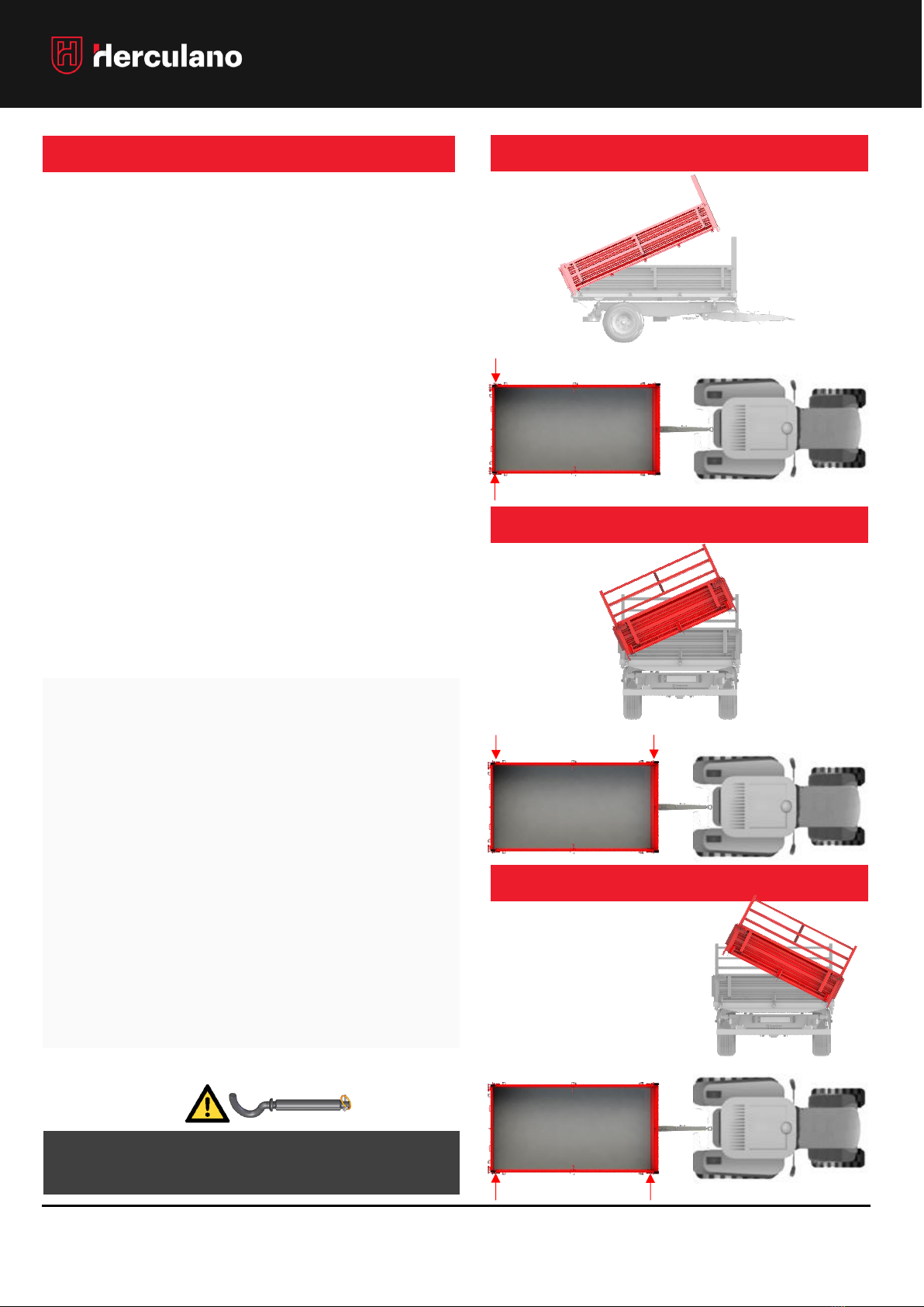
TIPPING TOWARDS THE REAR
TIPPING TO THE LEFT
TIPPING TO THE RIGHT
•Do not tip on slopes or slippery terrain!
•Do not allow people near the door or between the wheels.
Serious accidents can happen!
•Do not force the hydraulic tipping cylinder when it is at its full
stroke!
•Take precautions, do not compromise your safety or that of
others!
•Always respect the general road safety rules!
•Adjust the load of your trailer taking into account the terrain
where it circulates.
•Distribute the load evenly over the trailer box and do not
overload the vehicle.
•Be sure to align the tractor with the trailer before tipping
cylinder limit switch.
•Do not ride with the tipped box or the door open.
•Before starting tipping, fit the tipping pegs properly!
•Always fit the safety pin in the pegs!
Correct mounting of the pegs
Correct mounting of the pegs
Correct mounting of
the pegs.

OPERATOR’S MANUAL: S1ET
REV. 02.2022 16
HYDRAULIC SYSTEMS
HYDRAULIC BRAKING SYSTEM
WITH 3-POSITION VALVE
ADJUST
BRAKINGPRESSURE ON
THE 3-POSITION VALVE
This hydraulic braking system is equipped with a 3-
position valve that allows the intensity of the braking
forces to be adjusted according to the load it carries
Therefore, before driving with the trailer empty, half full
or completely full, you can adjust the valve to the
corresponding position in order to adjust the braking
forces to the load you are carrying.
The connection of this system is guaranteed using two
hydraulic hoses that must be connected to the brake
valve and a line with connection to the oil tank of the
tractor's braking system.
Make sure that you connect this system correctly each
time you proceed to the trailer's coupling.
Always respect speed limits to not jeopardize your
safety and the safety of others.
1º Carefully bring the tractor to the trailer drawbar in
order to engage, lock the tractor an turn of the
engine;
2º Connect the hydraulic hoses of the braking systems
in respective lines of the tractor;
“When connecting, make sure that the quick
connection valves are free from dirt.”
3º Start the tractor engine and teste the braking
system and check if the system works correctly.
NOTE: Do not drive on public roads if the braking system
is not working properly or if you detect any anomaly
that could jeopardize the safety of the vehicle or
people's safety!
NOTE: The braking system must be connected to the
tractor on the appropriate lines and it must not exceed
115 bar.
CONNECT THE HYDRAULIC
HOSES TO THE TRACTOR
TEST THE SYSTEM
BEFORE START
WORKING!
BRAKING VALVE –3 POSITIONS
MIN = EMPTY
MÉD
= ½ LOAD
MAX. = FULL (MAX PRESSURE = 115 bar)
The discharge line of this valve must be connected to a
tractor line connected to the oil tank of the trailer's braking
system. This line can be the floating line, if it exists and if it
matches the requirement mentioned above. When in
doubt, check the tractor's manual or ask the manufacturer
for support.
NOTE: A poor connection can damage the tractor!
WARNING!

OPERATOR’S MANUAL: S1ET
REV. 02.2022 17
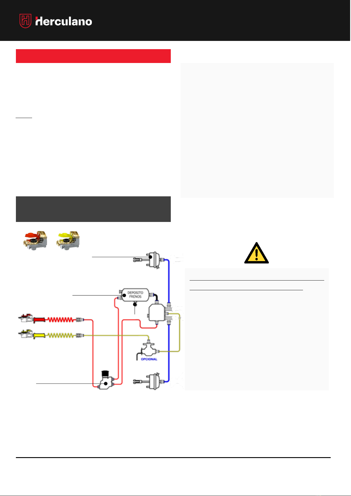
HYDRAULIC SYSTEMS
HYDRAULIC BRAKING SYSTEM with 3 POSITION
CONTROL + ELECTRICALLY CONTROL VALVES
This system was specifically developed to assist the
user to easily adjust the braking pressure
according to the load it transports on the trailer,
from an electric control placed on the tractor.
This way, with the help of the control, the driver
can change the braking pressures to:
0= EMPTY (35bar)
½= HALF LOAD (75bar)
1= FULL (115bar)
(Max Pressure = 115 bar)
HYDRAULIC BRAKING SYSTEM
CONTROL
COMMAND ON THE
TRACTOR
0= EMPETY
½= HALF LOAD
1= FULL
(Max pressure = 115 bar)
TRAILER
HYDRAULIC
BRAKING LINE
HYDRAULIC BRAKE LINE FROM
THE TRACTOR TO THE TRAILER
The installed hydraulic braking must be connected to the
tractor, through the hose that contains the ½ female
quick valve, as shown in the following diagram:
TEST THE SYSTEM
BEFORE START
WORKING!
CONNECT THE HYDRAULIC
HOSES TO THE TRACTOR
NOTE: The valves and control setting may
change depending on supplier or product
changes.
OPERATOR’S MANUAL: S1ET
REV. 02.2022 18
PNEUMATIC BRAKE SYSTEM
PNEUMATIC BRAKE SYSTEM
The pressure of the pneumatic braking system is
adjusted accordingly to the applied wheels.
It is essential to contact the manufacturer in case of
modifications to the factory assembly in order to
obtain the following technical information:
•CHECK THE COMPABILITY OF NEW TIRES WITH THE
VEHICLE;
•POSSIBLE PRESSURE ADJUSTMENT, ACCORDING
TO THE LOAD TO BE CARRIED OUT.
•
The pneumatic braking system should only be switched
on after the initial coupling of the trailer to tractor has
ended.
NOTE: Always test the system before starting work!
Do not drive on public roads if the system does not work
properly or if you detect any anomaly that could
jeopardize the safety of the vehicle or people's safety.
The pneumatic braking system, as well as other
systems, is one of the main safety elements of the
vehicle. It must in no way be neglected or
forgotten.
Keep systems in good condition and in good
working state. Make periodic revisions and if you
detect any wear or anomaly, repair the situation
immediately if you are qualified to do so. If needed,
contact your agent or request assistance directly
by the manufacturer.
PNEUMATIC BRAKING SYSTEM
(without ALB) / (without relay valve)
PNEUMATIC VASSEL
DEPRESSURIZATION
VALVE
PURGE
AIR TANK
(When applicable)
OPERATOR’S MANUAL: S1ET
REV. 02.2022 19
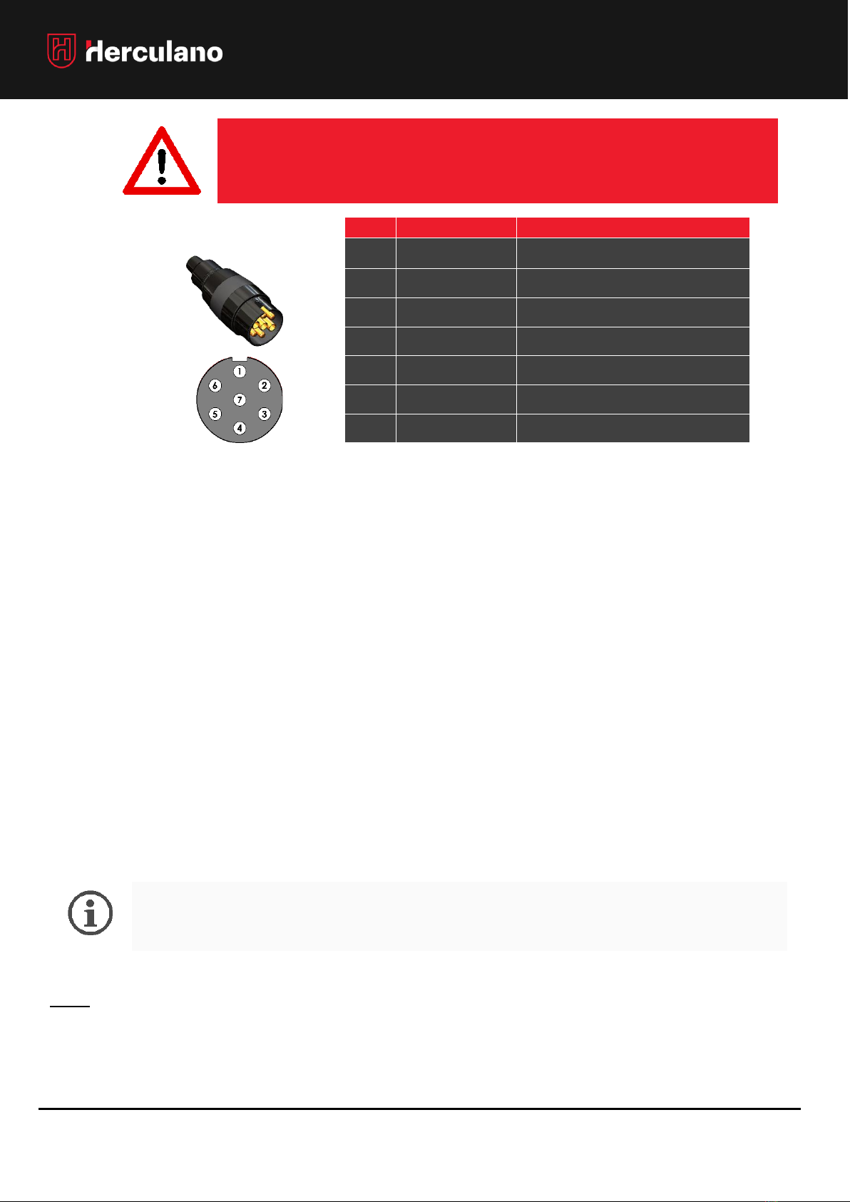
ELECTRICAL SYSTEM CONNECTION
PINO
COR
CIRCUITO
1
BLUE / (GREEN*)
DIRECTIONAL INDICATOR RIGHT (BLUE)
•OPTIONAL LED (GREEN)
2
WHITE (x2)
POSITION LIGHT
3
“LOSSE”/ (BLUE*)
•OPTIONAL LED
4
YELLOW
DIRECTION INDICATOR LEFT
5
RED
BRAKE LIGHT
6
BROWN (x2)
POSITION LIGHT
7
BLACK
MASS
WARNING: Failure to follow this warning may result in
property damage, serious injury or death.
PLUG
(Cod: 20303001)
To ensure good performance and durability of the trailer's lighting system and wiring, follow the following
procedure and inspection regularly:
1. Clean all reflective elements and other lighting devices thoroughly, before and after each use;
2. Check if all bulbs are working correctly and replace them if they are damaged or defective, as well as
reflective elements in poor condition;
3. When replacing, always use bulbs with the same characteristics than the originals and the same for
reflective components;
4. Inspect all cables and check for damage or cut. Cables must be properly supported, protected and
with the connection plugs tightened, dry and clean;
5. Damaged cables must be replaced by new ones with equal characteristics and size in order to
guarantee the connection of elements that they run to.
-The schematics of the lightning systems are represented in the expanded document: “Spare
Parts Lists “, which was attached to the Operator’s manual.
NOTE: If you need to test the bulbs, use a 12V - DC power supply. Never use battery chargers or transformers.
OPERATOR’S MANUAL: S1ET
REV. 02.2022 20
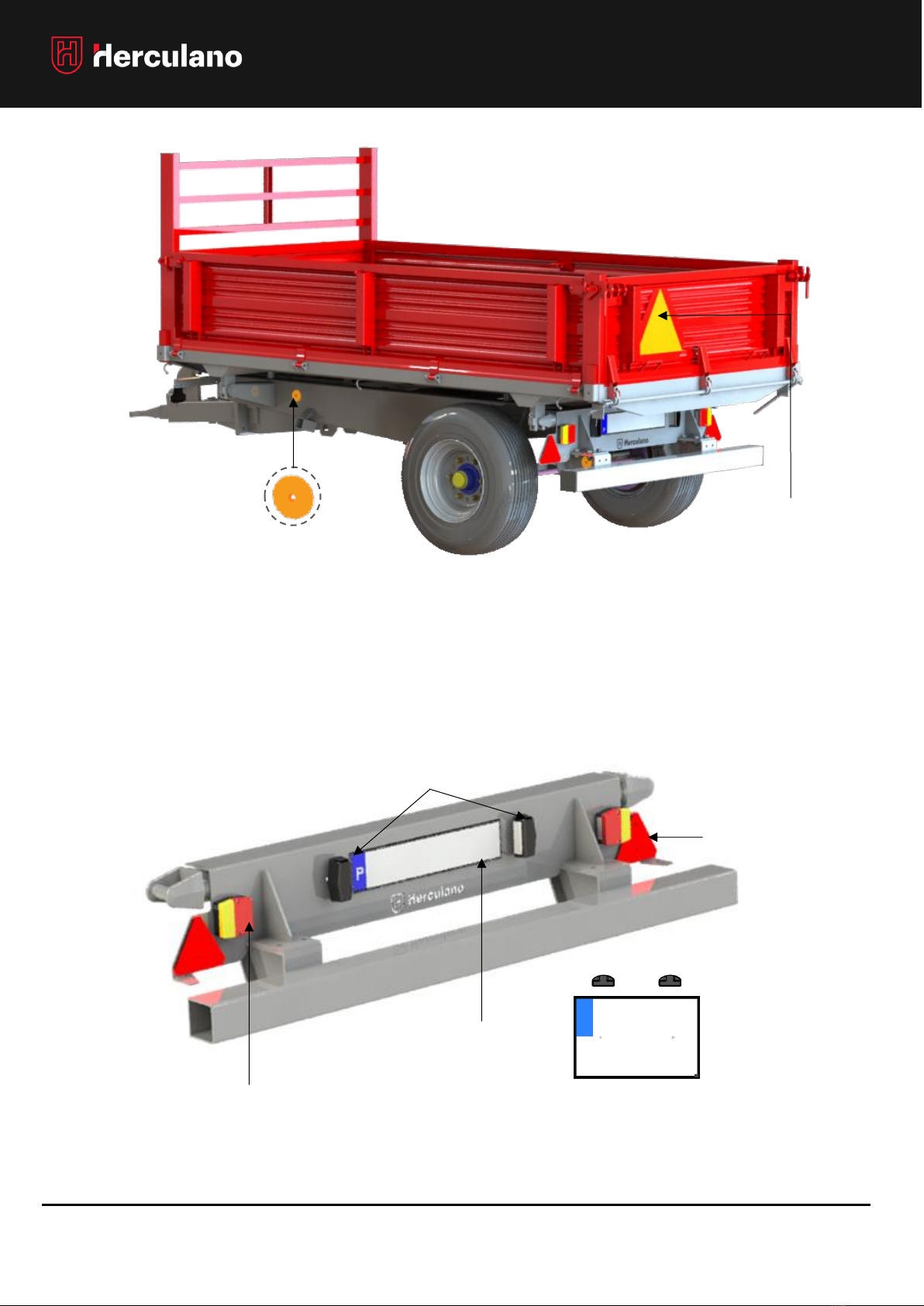
SIGNALING AND LIGHTNING
SLOW RUNNING
PLATE
FRONT LIGHT REFLECTOR AND
SIDE MARKER LIGHT
REGISTRATION PLATE
LAMPS
REGISTRATION PLATE* OR
REAR LIGHT
SLOW RUNNING PLATE
(*) –It varies depending on the legislation of each
country.
Table of contents
Other FERPINTA Farm Equipment manuals


Popular Farm Equipment manuals by other brands

Schaffert
Schaffert Rebounder Mounting instructions

Stocks AG
Stocks AG Fan Jet Pro Plus 65 Original Operating Manual and parts list

Cumberland
Cumberland Integra Feed-Link Installation and operation manual

BROWN
BROWN BDHP-1250 Owner's/operator's manual

Molon
Molon BCS operating instructions

Vaderstad
Vaderstad Rapid Series instructions


