InterPuls ACR Smart MMV Instruction Manual

THIS MANUAL IS THE PROPERTY OF - InterPuls S.p.A. - ANY COPYING, EVEN PARTIAL, IS STRICTLY PROHIBITED
MI - 2
MANUFACTURER
InterPuls S.p.A
ADDRESS
Via: F. Maritano, 11
Postal code 42020 - Albinea (RE) - ITALY
Tel.: +39 0522 347511
Telefax: +39 0522 348516
Website: www.milkrite-interpuls.com
E-mail: [email protected]
TYPE OF DOCUMENT
Instruction, Use and Maintenance Manual
DOCUMENT CODE
5760006_ EN
EDITION
02.17
PRODUCT
Control panel for automatic removal and milk meter
MODEL
ACR Smart MMV
YEAR OF MANUFACTURE
2017
InterPuls is a registered trade mark of InterPuls SpA.
The information contained in this document is not binding and can be modified without notice. References in
this document to manufacturer trademarks are for identification only. Certain company and product names
used throughout the document are trademarks of their respective owners.

ACR Smart MMV - Instruction Manual, Operation and
Maintenance original instructions
5760006_02.17_EN
THIS MANUAL IS THE PROPERTY OF - InterPuls S.p.A. - ANY COPYING, EVEN PARTIAL, IS STRICTLY PROHIBITED
MI - 3
Summary
ACR Smart MMV ............................................................................................................................................... 1
1GENERAL INFORMATION .................................................................................................................... 5
General information and safety warnings...................................................................................... 51.1
1.1.1 Important warnings .................................................................................................................... 5
1.1.2 Symbol used in this manual....................................................................................................... 5
1.1.3 Rules and regulations for the user............................................................................................. 5
1.1.4 Limitation of liability.................................................................................................................... 5
Prior using the product................................................................................................................... 51.2
1.2.1 Requirements and rules for personnel and Safety Rules.......................................................... 5
Disposal......................................................................................................................................... 61.3
1.3.1 General regulation ..................................................................................................................... 6
Fire prevention............................................................................................................................... 61.4
1.4.1 Fire prevention........................................................................................................................... 6
1.4.2 Safety regulations...................................................................................................................... 6
1.4.3 Characteristic of extinguishers................................................................................................... 6
Normative references applied........................................................................................................ 61.5
Marking.......................................................................................................................................... 61.6
1.6.1 Data plates affixed to the machine ............................................................................................ 6
2DESCRIPTION OF THE MACHINE ....................................................................................................... 7
General characteristics.................................................................................................................. 72.1
Technical features ......................................................................................................................... 72.2
Wiring diagrams............................................................................................................................. 8
2.3
2.3.1 Connection diagram with MMV sensor...................................................................................... 8
2.3.2 Connection diagram with HFS Flow sensor ............................................................................ 10
2.3.3 Choice of CV............................................................................................................................ 11
3DESCRIPTION OF THE DEVICE......................................................................................................... 12
Display during operation.............................................................................................................. 133.1
4DESCRIPTION OF THE FUNCTIONS................................................................................................. 14
Detachment phase (stand-by) ..................................................................................................... 144.1
Washing....................................................................................................................................... 154.2
4.2.1 Washing with HFS ................................................................................................................... 15
4.2.2 Washing with Milk Meter.......................................................................................................... 16
Milking.......................................................................................................................................... 164.3
4.3.1 Milking with automatic cluster removal.................................................................................... 16
4.3.2 Milking with HFS...................................................................................................................... 16
4.3.3 Milking with MMV..................................................................................................................... 17
4.3.4 Manual milking......................................................................................................................... 18
4.3.5 Maximum milking time ............................................................................................................. 18
Detachment operation ................................................................................................................. 184.4
Reattachment............................................................................................................................... 194.5

5760006_02.17_EN
ACR Smart MMV - Instruction Manual, Operation and
Maintenance original instructions
THIS MANUAL IS THE PROPERTY OF - InterPuls S.p.A. - ANY COPYING, EVEN PARTIAL, IS STRICTLY PROHIBITED
MI - 4
Stimulation................................................................................................................................... 204.6
Alarm............................................................................................................................................ 224.7
Quick-Lift...................................................................................................................................... 224.8
Swing-over (only with detachment made by pneumatic cylinder) ............................................... 224.9
Calibration (with MMV) ................................................................................................................ 234.10
4.10.1 Equipment............................................................................................................................ 23
4.10.2 Testing proceeding .............................................................................................................. 25
5PROGRAMMING MODE...................................................................................................................... 26
Accessing the programming mode.............................................................................................. 265.1
Modifying parameters .................................................................................................................. 265.2
Programming parameter table..................................................................................................... 275.3
6GENERAL RECCOMENDATION......................................................................................................... 29
Positioning ................................................................................................................................... 296.1
Sensitivity (only with HFS)........................................................................................................... 296.2
Power off...................................................................................................................................... 296.3
Configurations (only with HFS).................................................................................................... 306.4
Troubleshooting........................................................................................................................... 306.5
ACR Smart MMV - Instruction Manual, Operation and
Maintenance original instructions
5760006_02.17_EN
THIS MANUAL IS THE PROPERTY OF - InterPuls S.p.A. - ANY COPYING, EVEN PARTIAL, IS STRICTLY PROHIBITED
MI - 5
1 GENERAL INFORMATION
General information and safety warnings1.1
1.1.1 Important warnings
To safeguard the operator and prevent any damage to the equipment, before carrying out any kind of
operation it is important to have read and fully understood the instruction manual.
1.1.2 Symbol used in this manual
The following symbols are used in this manual to highlight indications and warnings which are of particular
importance:
WARNING
This symbol indicates health and safety regulations designed to protect operators and/or any
exposed persons.
CAUTION
This symbol indicates that there is a risk of causing damage to the equipment and/or its
components.
NOTE
This symbol is used to highlight useful information.
1.1.3 Rules and regulations for the user
WARNING
Any failure to observe the warnings provided in this manual may lead to equipment
malfunctions or damage to the system.
1.1.4 Limitation of liability
InterPuls S.p.A. declines all liability for damage to persons, animals and/or things caused by incorrect use of
the equipment.
Prior using the product1.2
1.2.1 Requirements and rules for personnel and Safety Rules
WARNING
Before using the device, the operator must carefully read the manual.
The person using the device must be of legal age and be trained and physically and mentally
fit. He or she must also have been provided with adequate information on how to operate the
device.
During the assembly and activation of the device, follow the instructions in the manual and
rules and regulations applying to health and safety at the workplace.
As the Portable ACR-SMART is an operator hand-held device, the operator must wear non-
slip safety shoes during use to prevent damage from accidental falls of the device

5760006_02.17_EN
ACR Smart MMV - Instruction Manual, Operation and
Maintenance original instructions
THIS MANUAL IS THE PROPERTY OF - InterPuls S.p.A. - ANY COPYING, EVEN PARTIAL, IS STRICTLY PROHIBITED
MI - 6
Disposal1.3
1.3.1 General regulation
The appliances must be disposed of only and exclusively by specially authorized waste disposal companies
in accordance with all relative legislation and prescriptions.
The packaging must be consigned to the relative authorized companies to be recycled.
Fire prevention1.4
1.4.1 Fire prevention
NOTE
The machine is not equipped with fire extinguishers.
The operator must make sure that the place in which the appliance is installed is equipped
with an adequate number of suitable fire extinguishers. The extinguishers must be positioned
where they are clearly visible and protected from damage and improper use.
1.4.2 Safety regulations
WARNING
It is strictly prohibited to extinguish fires involving electrical equipment with water!
1.4.3 Characteristic of extinguishers
Use powder, foam or halogen extinguishers which must be positioned next to the device.
Operating personnel must receive adequate instruction on how to use the extinguishers.
Normative references applied1.5
Europe:
Directive no. 2004/108/EC Electromagnetic Compatibility (EMC)
USA:
FCC Federal Communications Commission
Canada:
IC Industry Canada
Marking1.6
1.6.1 Data plates affixed to the machine

ACR Smart MMV - Instruction Manual, Operation and
Maintenance original instructions
5760006_02.17_EN
THIS MANUAL IS THE PROPERTY OF - InterPuls S.p.A. - ANY COPYING, EVEN PARTIAL, IS STRICTLY PROHIBITED
MI - 7
2 DESCRIPTION OF THE MACHINE
General characteristics2.1
The ACRSmart MMV is a panel designed to control all the functions of milking, washing and detachment of
the unit.
Furthermore, with InterPuls Milk Meter, ACRSmart MMV is able to measure the milk production with errors
below 2%.
The panel can work with Milk Meter InterPuls and also with flow sensor HFS InterPuls.
The ACRSmart MMV is able to control the milking frequency and the pulsation ratio in a wide range of values
in order to meet the needs of all system (both in high line and low line) and of all type of animals (cattle –
sheep –goat).
The ACRSmart MMV is able to perform a stimulation that can be forced, automatic (dependent on the flow of
milk) or manual (activated directly by the milker at any time).
The panel is compatible with swing-over systems in which the unit is detached by moving the arm. In fact,
with the ACRSmart MMV you can control the pneumatic cylinder responsible for moving the unit from the
right hand row to the left hand row and vice versa.
It is suitable for milk transport systems thanks to the alarm indicating the end of the milking process and the
possibility to restart the panel from the last active stage.
The ACRSmart MMV can be connected to remote start-up devices (AutoStart) and remote stop devices
(Quick Lift Line).
Technical features
2.2
General technical characteristics
Dimensions
130x180x38 mm (5.12x7.08x1.5 in)
Weight
0.45 kg (0.99 lb)
Power supply
24 VDC
Power consumption (only panel)
max 60 mA
Power consumption (entire system)
Panel –Milk Meter –LE30 –CV –½ LE30
- alarm
max 600mA
Protection rating (cables installed properly)
IP 67
Operating vacuum
between 20 and 60kPa (between 5.9 and 17.71 “Hg)
Operating temperature (environment)
+3ºC ÷ +40ºC (+37.4°F ÷ +104°F)
Transport/storage temperature
-20ºC ÷ +50ºC (-4°F ÷ +122°F)

5760006_02.17_EN
ACR Smart MMV - Instruction Manual, Operation and
Maintenance original instructions
THIS MANUAL IS THE PROPERTY OF - InterPuls S.p.A. - ANY COPYING, EVEN PARTIAL, IS STRICTLY PROHIBITED
MI - 8
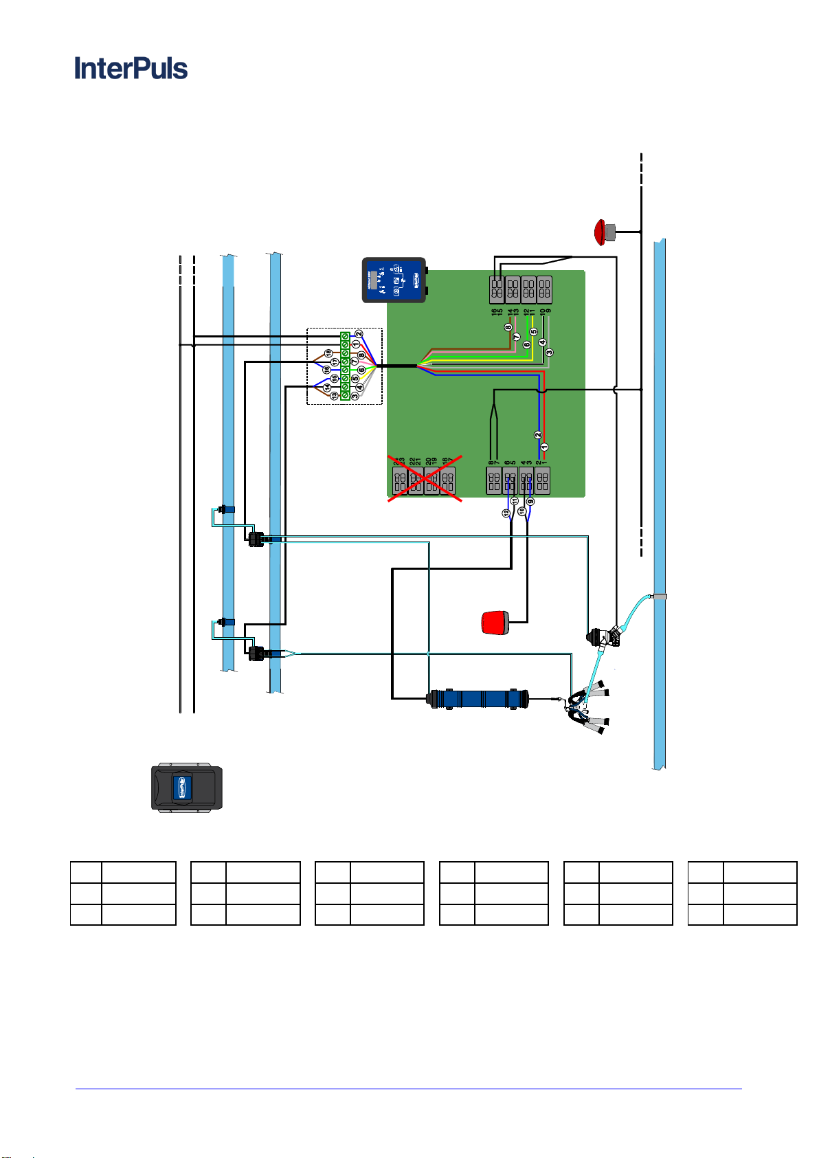
Wiring diagrams2.3
2.3.1 Connection diagram with MMV sensor
Blue
Brown
Black
Blue
29
30
31
32
Pink
Brown
Brown
Black
25
26
27
28
Grey
White
Yellow
Green
21
22
23
24
Blue
Black
Red
Blue
17
18
19
20
Black
Blue
Black
Brown
13
14
15
16
Black
Shield
Blue
Black
9
10
11
12
Grey
Pink
Blue
Red
5
6
7
8
Brown
White
Green
Yellow
1
2
3
4
IUP
MMV
IUP
FILTERED AIR LINE
VACUUM LINE
MILK LINE
ACR Smart
MMV
+24VDC
-24VDC
CV20
LE30
CV30
VAC/ATM
MMV
DVC AS
END OF
MILKING
LAMP
QUICK-LIFT
BUTTON
TO THE
NEXT PANEL
TO THE
NEXT PANEL
ATM
VAC
ADDITIONAL
VACUUM LINE
(minØ40)
ACR Smart MMV - Instruction Manual, Operation and
Maintenance original instructions
5760006_02.17_EN
THIS MANUAL IS THE PROPERTY OF - InterPuls S.p.A. - ANY COPYING, EVEN PARTIAL, IS STRICTLY PROHIBITED
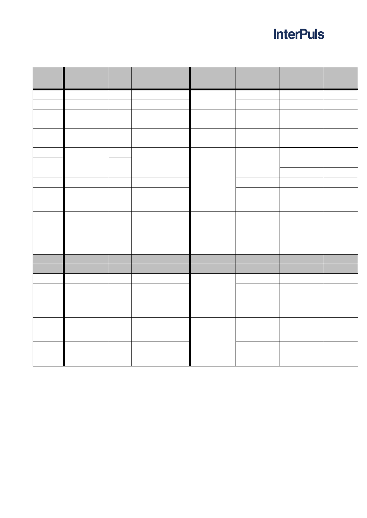
MI - 9
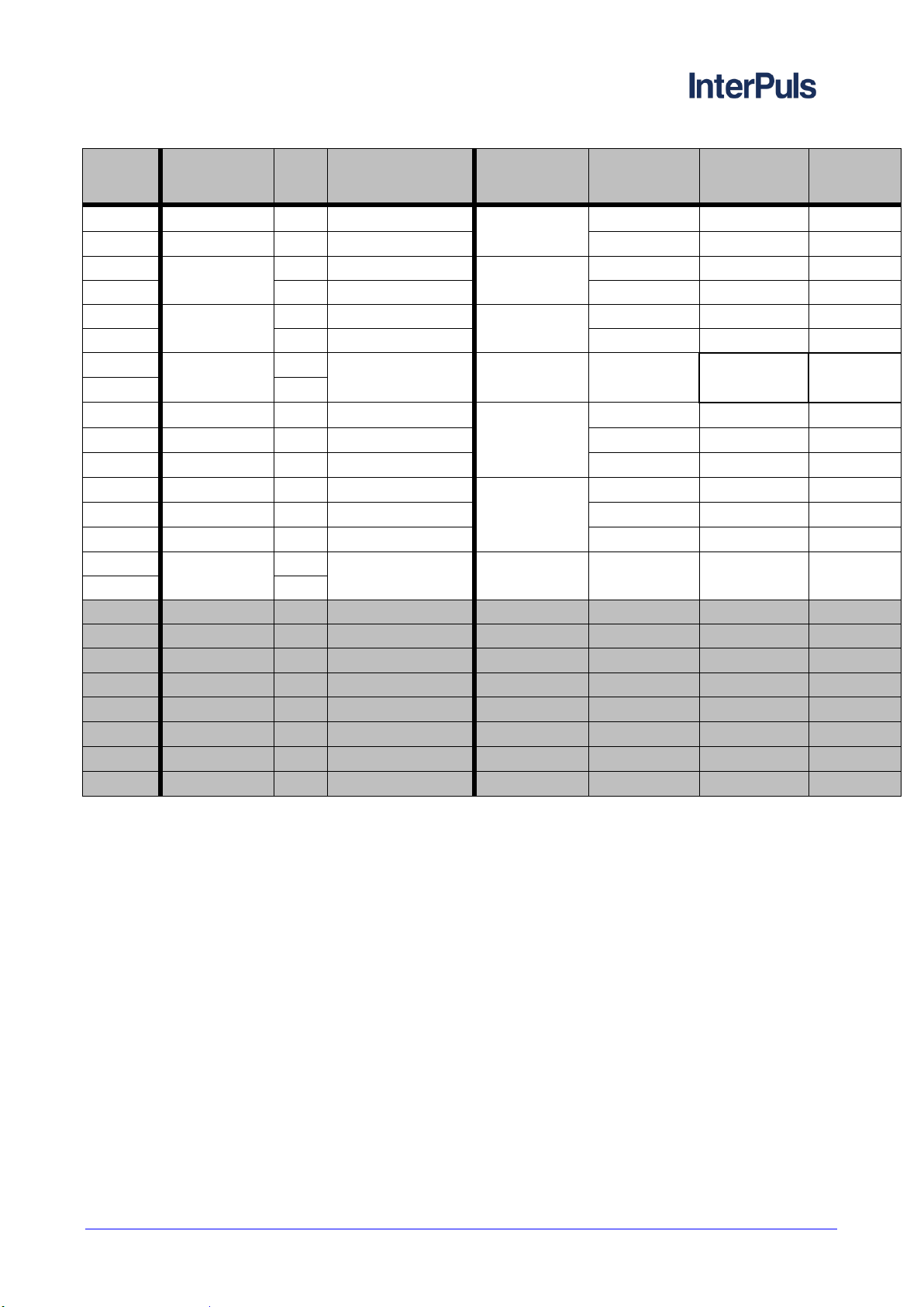
N°
terminal
PCB
Wiring
N°
wire
Color
Description
Type of
wiring
Wire color
(device side)
N° wire
(device
side)
1
8 poles cable
19
Red
PCB power
supply
24 VDC (+)
-
-
2
8 poles cable
20
Blue
24 VDC (-)
-
-
3
End of milking
lamp
11
Blue
Lamp power
supply
24 VDC (+)
-
-
4
12
Black
24 VDC (-)
-
-
5
DVC AS
13
Black
Autostart
-
-
-
6
14
Blue
-
-
-
7
Quick lift line
-
Clean contact
-
-
-
-
8
-
9
8 poles cable
21
Grey
LE30
Rear
Brown
27
10
8 poles cable
22
White
Common
Black
28
11
8 poles cable
23
Yellow
Front
Blue
29
12
8 poles cable
24
Green
CV
Left channel
(S/O)
Brown
30
13
CV (2x2)
15
Black (blue for the
second milking
point)
Detachment
(DVC)
Common
-
-
14
16
Brown (grey for the
second milking
point)
to the DVC
-
-
15
16
17
MMV cable
8
Red
Temperature
probe
Ground
Black
9
18
MMV cable
7
Blue
IN
Black
9
19
8 poles cable
25
Pink
CV
Common
Black
31
20
8 poles cable
26
Brown
Right channel
(dump valve)
Blue
32
21
MMV cable
4 e 10
White + shield
MMV power
supply
5 VDC (-)
White
4
22
MMV cable
22
Yellow
Level
LIV 2
Yellow
3
23
MMV cable
23
Green
LIV 1
Green
2
24
MMV cable
24
Brown
MMV power
supply
5 VDC (+)
Brown
1
5760006_02.17_EN
ACR Smart MMV - Instruction Manual, Operation and
Maintenance original instructions
THIS MANUAL IS THE PROPERTY OF - InterPuls S.p.A. - ANY COPYING, EVEN PARTIAL, IS STRICTLY PROHIBITED
MI - 10
2.3.2 Connection diagram with HFS Flow sensor
1
Rosso
4
Bianco
7
Rosa
10
Nero
13
Marrone
16
Blu
2
Blu
5
Giallo
8
Marrone
11
Nero
14
Nero
17
Nero
3
Grigio
6
verde
9
Blu
12
Blu
15
Blu
18
Marrone
IUP
CV20
VACUUM LINE
LE30
+24VDC
-24VDC
FILTERED AIR LINE
MILK LINE
HFS EVO
ACRSmart MMV
QUICK-LIFT
BUTTON
TO THE NEXT
PANEL
DVC AS
END OF
MILKING
LAMP
ACR Smart MMV - Instruction Manual, Operation and
Maintenance original instructions
5760006_02.17_EN
THIS MANUAL IS THE PROPERTY OF - InterPuls S.p.A. - ANY COPYING, EVEN PARTIAL, IS STRICTLY PROHIBITED
MI - 11
2.3.3 Choice of CV
It’s possible to set the ACRSmart MMV panel in order to use solenoid valves normally open or normally
closed by setting the following parameters:
- E.S-O : shut-off solenoid valve
- E.DVC : cylinder solenoid valve
- E.dMP. : dump valve solenoid valve
Set these parameters on:
- N.OP. (normally open) if the utility is connected to a VAC channel of the CV (eg. for CV20 or left
channel of CV30 inv)
- N.CL. (normally closed) if the utility is connected to a ATM channel of the CV (eg. for CV30 or
right channel of CV30 inv)
The default settings require the utilization of a CV20 for cylinder (E.DVC = N.OP.) and a CV30 inv for
shut-off and for dump valve (E.S-O = N.OP. , E.dMP. = N.CL.)
N°
terminal
PCB
Wiring
N°
wire
Color
Description
Type of
wiring
Wire color
(device side)
N° wire
(device
side)
1
8 poles cable
1
Red
PCB power
supply
24 VDC (+)
-
-
2
8 poles cable
2
Blue
24 VDC (-)
-
-
3
end of milking
lamp
9
Blue
Lamp power
supply
24 VDC (+)
-
-
4
10
Black
24 VDC (-)
-
-
5
DVC AS
11
Black
Autostart
-
-
-
6
12
Blue
-
-
-
7
Quick lift line
Clean contact
-
-
-
-
8
9
8 poles cable
3
Grey
LE30
Rear
Brown
13
10
8 poles cable
4
White
Common
Black
14
11
8 poles cable
5
Yellow
Front
Blue
15
12
8 poles cable
6
Green
CV30
to S/O
Blue
16
13
8 poles cable
7
Pink
Common
Black
17
14
8 poles cable
8
Brown
to the DVC
Brown
18
15
HFS
Clean contact
Milk flow
-
-
-
16
17
18
19
20
21
22
23
24
5760006_02.17_EN
ACR Smart MMV - Instruction Manual, Operation and
Maintenance original instructions
THIS MANUAL IS THE PROPERTY OF - InterPuls S.p.A. - ANY COPYING, EVEN PARTIAL, IS STRICTLY PROHIBITED
MI - 12
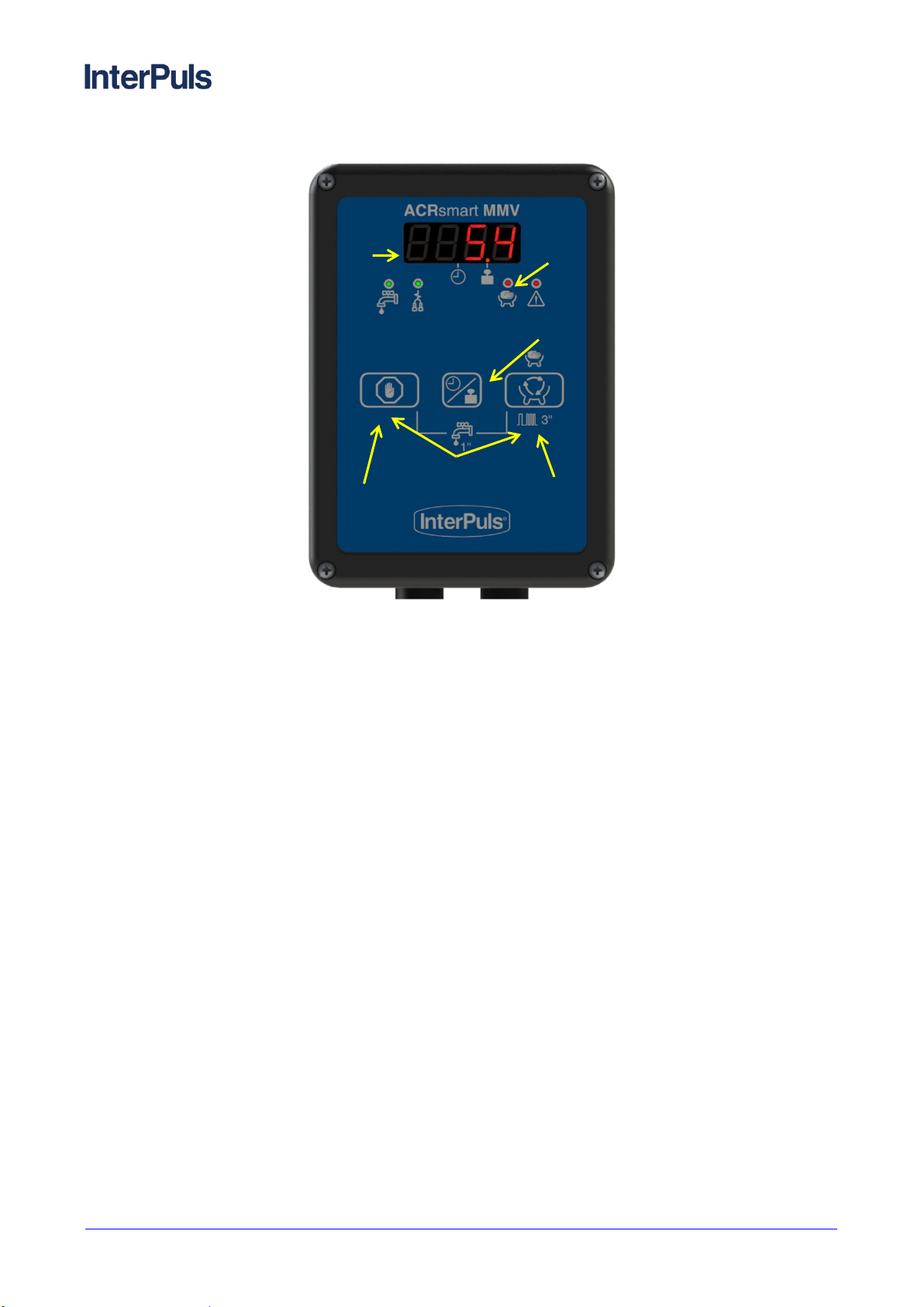
3 DESCRIPTION OF THE DEVICE
A) Display
B) LEDs (green and red)
C) STOP key
D) Milking process START button with automatic detachment, continuous pressure for 3’’ stimulation
start
E) Key to show milk production or milking time
F) Combination of key for accessing the washing or programming mode
A
F
B
D
C
E
ACR Smart MMV - Instruction Manual, Operation and
Maintenance original instructions
5760006_02.17_EN
THIS MANUAL IS THE PROPERTY OF - InterPuls S.p.A. - ANY COPYING, EVEN PARTIAL, IS STRICTLY PROHIBITED
MI - 13
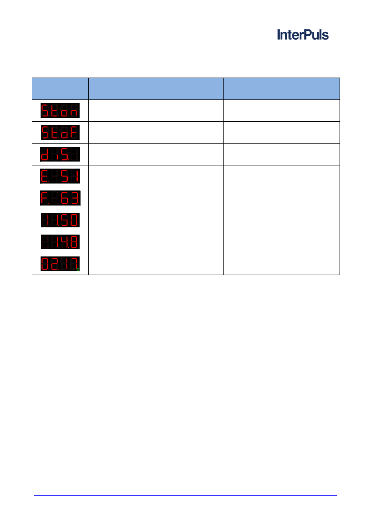
Display during operation3.1
Display
Indication
Meaning
Code St.on.
Start of stimulation
Code St.oF.
End of stimulation
Code diS
Washing (only with HFS sensor)
Code E + temperature
EMPTY phase during washing and
temperature indication (only with MMV
sensor)
Code F + temperature
FILL phase during washing and
temperature indication (only with MMV
sensor)
xx.xx with point on time symbol
Milking time
xx.x with point on quantity symbol
Milk production (only with MMV sensor)
Right point blinking
Continuous milk flow

5760006_02.17_EN
ACR Smart MMV - Instruction Manual, Operation and
Maintenance original instructions
THIS MANUAL IS THE PROPERTY OF - InterPuls S.p.A. - ANY COPYING, EVEN PARTIAL, IS STRICTLY PROHIBITED
MI - 14
4 DESCRIPTION OF THE FUNCTIONS
Upon start-up the panel display indicates the software version installed. Depending on the configured
settings (parameter In.P.), then the panel starts during:
- washing
- detachment (default)
- last active phase
Detachment phase (stand-by)4.1
Depending on the settings (parameter dEF.P.), the panel shows the milking production (point on
symbol) or the milking time (point on symbol) of last animal; at the start, the display shows time and
production equal to zero.
Green led of detachment is on to signal that the cluster is in removal position. The S/O valve stays
closed, while the unit position may switch from release to removal or vice versa by pressing STOP button
or via cluster up/down line; when the unit is released, the green led turns off.
Key
Function
briefly
Start automatic milking (reset of milking time and milk measurement)
briefly
Removal or release of the milking unit
+ briefly
Start washing
+ x 10”
Access programming mode
briefly
Change display visualization from milking time to milk quantity and vice
versa
hold
Show the whole milking production (from last reset)
hold +
Reset the whole milking production
hold +
Reattached the same animal (keep the last milking time and the last milk
production)
QUICK-LIFT operation
Removal or release of the milking unit
AUTO-START operation
Start automatic milking via remote control (cylinder with auto-start or
remote button)

ACR Smart MMV - Instruction Manual, Operation and
Maintenance original instructions
5760006_02.17_EN
THIS MANUAL IS THE PROPERTY OF - InterPuls S.p.A. - ANY COPYING, EVEN PARTIAL, IS STRICTLY PROHIBITED
MI - 15
Washing4.2
The wash phase can be operated:
Manually when the system is in detachment position by pressing together + briefly
Automatically if pre-set as the start-up phase on the programming menu (parameters In.P. set on
diS.)
By pressing STOP button during washing, the phase stops and the panel returns to stand-by mode,
the unit is not removed from washing plate.
By pressing again the STOP button the cluster is removed.
CAUTION
At the end of washing phase it’s recommended to power off the ACRSmart MMV panels to
avoid that the coils of control valves stay powered for long time and being damaged. Upon
start-up, the panel may restart in washing phase or detachment phase according to the
parameter In.PH.
4.2.1 Washing with HFS
Washing visualization with HFS
The display features the code diS. And the green washing led starts blinking. The unit is released and
the count relating to the shut-off closure delay starts (parameter c.S.d.). When it is elapsed, the shut-off
valve is opened and the washing stage starts.
It’s possible to change the frequency during washing (parameter diS.F.).
Press the STOP button or the cluster up/down command to stop washing cycle and retract the unit.
5760006_02.17_EN
ACR Smart MMV - Instruction Manual, Operation and
Maintenance original instructions
THIS MANUAL IS THE PROPERTY OF - InterPuls S.p.A. - ANY COPYING, EVEN PARTIAL, IS STRICTLY PROHIBITED
MI - 16
4.2.2 Washing with Milk Meter
The panel alternates FILL phase and EMPTY phase; between the two phases, the dump-valve is activated
to allow the emptying of the sensor.
During the FILL phase, the dump-valve stays closed to permit the complete filling of the milk meter to wash it
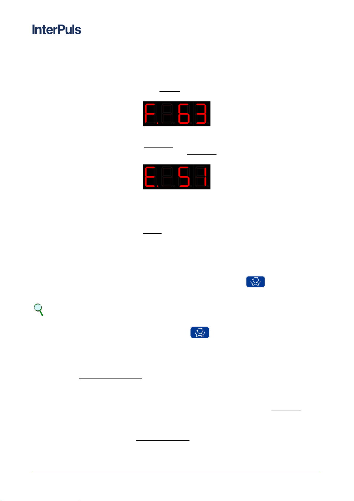
in each of his part. The FILL phase lasts for the Fill time (parameter FILL).
The display features code “F” and the temperature of the water.
FILL phase with water at 63°C (145.4°F)
During the EMPTY phase, the dump-valve is closed until the floater reaches the second level. Then the shut-
off stays open as setting in the parameter Dump time (parameter dMP.t.) to discharge the water. After that
the milk meter starts again to fill and to discharge until the Empty time elapsed (parameter EMPt).
The display features code “E” and the temperature of the water.
EMPTY phase with water at 51°C (123.8°F)
The washing parameters have to be modified to allow the complete filling and emptying of the sensors.
Depending from the parlour configuration, you may need to set different values of FILL and EMPt
parameters to allow the correct washing of each sensor.
In the milking points far from the water entrance, if there isn’t enough water to completely filling of the sensor
(FILL PHASE), it’s necessary to increase fill time (parameter FILL); equally, to make available more water,
it’s also possible to increase empty time (parameter EMPt).
Milking4.3
4.3.1 Milking with automatic cluster removal
To start the milking process with automatic detachment press the START button during detachment
phase or operate the Auto-start contact.
NOTE
The connectors 5-6 (clean contact) can be connected to a REMOTE BUTTON or an AUTO-
START cylinder to start a milking without using button.
When the milking with automatic detachment starts:
Cylinder releases the unit
After the Vacuum/pulsation delay (parameter PuL.d.), the pulsator is activates and the shut-off valve
is opened.
4.3.2 Milking with HFS
At the beginning of the milking, the display shows the milking time and the panel counts of Initial delay
(parameter In.d.).
When the milking presence signal constantly exceeds the value defined by the position of the jumpers, the
panel detects a presence of milk and the first dot on the right starts blinking.
If the presence of milk lasts more than Continuous flux time (parameter M.d.F.), the panel detects a real milk
flux.

ACR Smart MMV - Instruction Manual, Operation and
Maintenance original instructions
5760006_02.17_EN
THIS MANUAL IS THE PROPERTY OF - InterPuls S.p.A. - ANY COPYING, EVEN PARTIAL, IS STRICTLY PROHIBITED
MI - 17
The panel shows the milking time in MM.SS size; the central dot is on clock symbol .
At the end of Initial delay (parameter In.d.) when there’s no longer milk flux, the count of Final delay
(parameter Fin.d.) starts; the detachment operations start when this delay has elapsed.
Milking time (4minutes and 58 seconds) with milk flow
During all milking stages, press the START button to switch from automatic to manual milking and
vice versa.
Press STOP button (or activate the Cluster up/down button) to immediately stop the milking and
start the detachment operations.
4.3.3 Milking with MMV
At the beginning of the milking, the panel starts counting of Initial delay (parameter In.d.).
The display can show:
- Milk yield (if parameter dEF.P = MiLK) –point on symbol
Milk yield (14.8 Kg)
- Milking time (if parameter dEF.P = tiME) –point on symbol
Milking time (2 minutes and 17 seconds) with milk flow
It’s always possible to pass from milk yield to milking time visualization and vice versa by pressing
button.
During milking, the point in the right corner of the display shows if in that moment there’s milk in the sensor. If
the milk flow is higher than the parameter Detachment flow (parameter dEt.F.), the panel detects a
continuous flow.
At the end of Initial delay (parameter In.d.), when there is no longer any milk flow, the panel start counting
final delay (parameter Fin.d.). The detachment operations start when this delay has elapsed.
During all milking stages, press the key to switch from automatic milking to manual milking and vice
versa.
Press the key (or activate the quick-lift button) to immediately stop the milking operations and start
the detachment operations.

5760006_02.17_EN
ACR Smart MMV - Instruction Manual, Operation and
Maintenance original instructions
THIS MANUAL IS THE PROPERTY OF - InterPuls S.p.A. - ANY COPYING, EVEN PARTIAL, IS STRICTLY PROHIBITED
MI - 18
4.3.4 Manual milking
To start milking with manual unit removal, press the key after the system has been started in
automatic milking mode:
The red led of manual milking stays on
The panel stays in the manual milking mode as long as:
the button is pressed to switch to the automatic milking mode
or
the button is pressed to start the detachment operations
Press the key to switch from the manual milking mode to the automatic milking mode and vice versa,
at any time.
4.3.5 Maximum milking time
WARNING
You can envisage a maximum milking time, which can be set or disabled in the programming
menu (parameter M.M.t.)
If this limit is reached, the unit detachment operations start automatically and, in the event of
no flow during the milking process, the anomaly is signaled via an alarm (see chapter 4.7
Alarm)
Detachment operation4.4
When the Initial delay (parameter In.d.) has elapsed, if the panel does not detect a continuous flow (HFS) or
a minimum flow (MMV) of milk, the final delay count starts (parameter Fin.d.) and the green led of
detachment starts flashing .
If the flow of milk is resumed, the delay is reset. The unit removal operations start when the final delay has
elapsed.
The removal procedure can also be started manually by pressing the key o by activating Quick-Lift
button.
When the detachment operation start:
the pulsator stops
the S/O Valve closes the vacuum passage
the detachment delay time count starts (parameter det.d.), in order to wait for a certain amount of air
to leak through the collection unit hole, lowering the vacuum level under the nipples before removing
the unit
when the delay has elapsed, the cylinder gently removes the unit and the green led stays fixed
on.
if the suction function has been activated (parameter SPt.L.), when the suction delay time has
elapsed (parameter SPt.d.) the residue milk in the collection unit and in the milk pipe is aspirated
through the flow meter.

ACR Smart MMV - Instruction Manual, Operation and
Maintenance original instructions
5760006_02.17_EN
THIS MANUAL IS THE PROPERTY OF - InterPuls S.p.A. - ANY COPYING, EVEN PARTIAL, IS STRICTLY PROHIBITED
MI - 19
if the automatic unit release function has been activated, when the automatic release delay has
elapsed (parameter A.r.d.) the unit is released automatically to start a new milking session.
At the end of detachment operation the green led of detachment stays fixed on and the display shows
the milking time or the milk yield (only with MMV). The pair of terminals 3-4 is powered at 24VDC; the pair of
terminals can be connected to a flashing light for indicating the end of milking.
Press the key to switch off the flashing light and the cylinder releases the milking unit (you can put it
on washing plates).
Press key to start a new milking session.
Press key to switch the display visualization from milking time to milk yield and vice versa (only with
MMV).
If you press and hold key, the display shows the total milk yield from the last reset (only with MMV).
If you press and hold key and then press also key, the total milk yield is reset.
Reattachment4.5
At the end of detachment operation, if the farmer believes that the animal still has milk, it’s possible to make
a reattachment, that is a new milking but without milking time and milk yield reset (these data restart from
the values of the last detachment).
To make a reattachment, press and hold key and then press also key. The reattachment is like
a normal milking and at the end start the detachment operation.
5760006_02.17_EN
ACR Smart MMV - Instruction Manual, Operation and
Maintenance original instructions
THIS MANUAL IS THE PROPERTY OF - InterPuls S.p.A. - ANY COPYING, EVEN PARTIAL, IS STRICTLY PROHIBITED
MI - 20
Stimulation4.6
At the beginning of stimulation, the display features the code St.on. for 3 seconds.
On the programming menu you can define the type of stimulation (parameter St.tY.) which may be:
Forced (Forc)
Automatic (Auto)
OFF (oFF) –can only be activated manually
FORCED STIMULATION
During programming you can set a forced stimulation cycle at the beginning of each milking process.
For a certain period of time (stimulation time, which can be set via parameter St.t.) the frequency
and pulsation ratio are gradually modified in order to reach the set values (stimulation frequency
St.F., stimulation ratio St.r.)
AUTOMATIC STIMULATION
Stimulation starts if the function is enabled and if during milking the sensor does not detect presence
of milk for a certain period of time (called neutral time, which can be set via parameter nEU.t.
Therefore the frequency and pulsation ratio vary gradually until reaching the values set for
stimulation (stimulation frequency St.F., stimulation ratio St.r.)
Stimulation stops when the flow meter starts detecting a presence of milk again or when the
stimulation time elapses (parameter St.t.)
MANUAL STIMULATION
Press and hold the key for 3” during the milking cycle (with any value set for parameter
St.tY.) to start the manual stimulation process: the frequency and pulsation ratio vary gradually until
reaching the values set for stimulation (stimulation frequency St.F., stimulation ratio St.r.).
Stimulation stops when the stimulation time has elapsed (parameter St.t.).
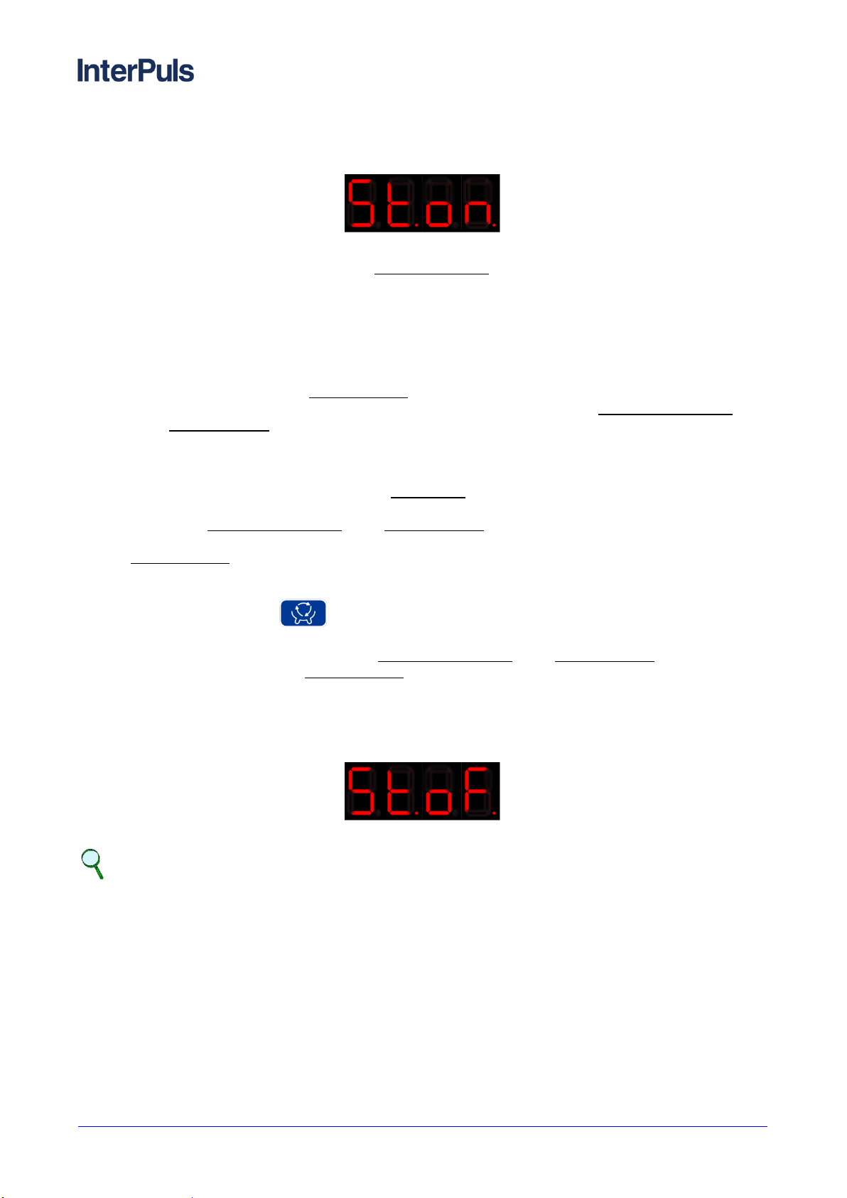
A couple of second before the stop of stimulation, the display features the code St.oF. for 3 seconds, after
that the frequency and pulsation ratio gradually go back to the values set for milking. Then the display
features again the milking time or the milk yield
NOTE
By setting stimulation ratio (parameter St.r.) on value 0, upon start of the stimulation, the
liners stay completely closed and the pulsation stops until the end of stimulation time (St.t.).
Table of contents
Popular Industrial Equipment manuals by other brands


Roger Technology
Roger Technology FU Series INSTRUCTIONS AND RECOMMENDATIONS FOR THE INSTALLER

MK
MK GUF-P Technical documentation

HWH
HWH 625 Series Operator's manual

BWT
BWT Permaq Pro 2100 Series Installation and operating manual

Siemens
Siemens 3TL71 operating instructions

Vega
Vega POINTRAC 31 operating instructions