intervolt DCC Pro User manual
INSTALLATION & OPERATION MANUAL
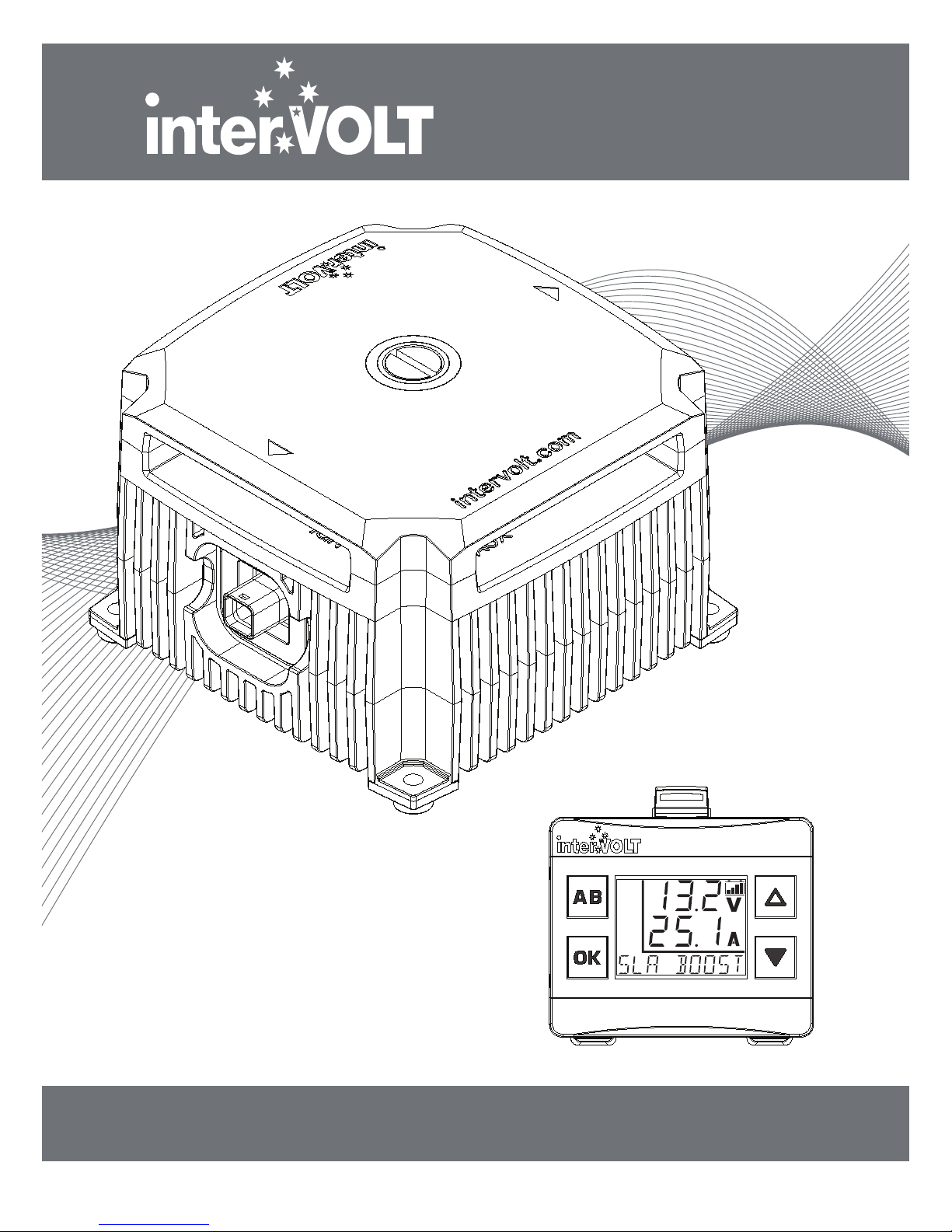
DCC Pro
In-Vehicle DC-DC
Battery Charger
12VDC 25 AMPS

WELCOME
Thank you for choosing an interVOLT product...
We, at Amelec Australia Pty Ltd, are very pleased to announce the release of our
rst in-vehicle battery charging system – the DCC Pro.
An in-vehicle or DC-DC charger is designed to charge a secondary battery using
the main battery as the charging source independent of the vehicle’s charging
system. There are several features and benets which set the DCC Pro apart
from the current oerings on the market. An introduction to the unique and
innovative DCC Pro can be found on the Overview page in this manual.
Amelec Australia Pty Ltd, a wholly owned and operated Australian private
company, is the proud owner of the interVOLT brand, a trademark which is
registered in over 20 countries worldwide. We have been producing specialised
power conversion products for over 10 years. All our products are designed,
developed and assembled in-house at our premises in Perth, Western Australia
from both local and imported components.
Our design ethos is based on quality, performance and value and we are
committed to product development in the DC power control and conversion
eld. With roots in the commercial marine, transport, alternate energy and
allied industries, we are now expanding into the consumer market with
dedicated products such as the DCC Pro.
InterVOLT products are designed to cope with the demands of the harshest
applications in high temperature and high humidity environments. They are
constructed of quality materials (marine grade where applicable) and designed
to provide many years of continuous service.
Again, thank you for choosing an interVOLT product and supporting Australian
innovation, technology and intellectual property.

CONTENTS
1
OVERVIEW .............................................................. 2
Introduction ............................................................ 2
Kit Contents............................................................ 3
Application.............................................................. 4
Synopsis................................................................. 5
FUNDAMENTALS .................................................... 6
Charging Modes ...................................................... 6
Charging Methods ................................................... 7
Layout - the Charging Device ..................................... 8
Layout - the Remote Display ...................................... 9
Standard Wiring Diagram ....................................... 10
Wiring using two Charging Devices........................... 11
INSTALLATION ...................................................... 12
Planning the Installation .......................................... 12
Installing the Charging Device .................................. 13
Wiring the Charging Device ..................................... 14
Installing the Data Cable ......................................... 15
Installing the Remote Display ................................... 16
Connection and Configuration .................................. 17
Installation Steps ................................................... 18
OPERATION........................................................... 24
Operating Brief ...................................................... 24
Operator Convenience Settings ................................ 26
Operator Control Functions ..................................... 28
Operator Monitoring Functions................................. 29
System Status....................................................... 31
TROUBLESHOOTING .............................................. 32
Alert Conditions..................................................... 32
Error Conditions .................................................... 33
SPECIFICATIONS ................................................... 34
DIMENSIONS ........................................................ 35
APPENDIX ............................................................ 36
Fundamentals in Detail ........................................... 36
WARRANTY POLICY .............................................. 41

OVERVIEW
2
Introduction
In a standard dual or multiple battery arrangement, the system will consist of a
starting (or main) battery and secondary (or auxiliary) batteries. For clarity and
conciseness we will refer to these throughout the manual as the main and
auxiliary batteries.
As a concept our vision for the DCC Pro was a device which would not only
provide an autonomous charging method for any auxiliary battery, but would
reliably, accurately and repeatedly provide feedback to the operator on the
status of the charging and maintenance process. In order to provide this
information it was necessary to integrate a visual display. The addition of a
remote display also provided the opportunity for a level of operator input,
allowing some control of the device, such as selection of battery types for
example. The development of a true remote user interface enabled the concept
to evolve into the product you have purchased today.
The DCC Pro consists of three main components. These form a complete‘plug
and play’kit and are all that is necessary, aside from the external wiring, to
implement a fully operational charging and maintenance system for one
auxiliary battery. The components consist of:
1. The Charging Device. This is the power conversion component of the
system. It is a high power, yet compact package which is designed to be
installed in the engine bay of the vehicle.
2. The Remote Display. This is the separate control and monitoring device
which is designed to be installed in the vehicle cabin in easy view and reach of
the operator. It has a backlit LCD display and four control buttons.
3. The Data Cable. This is the interconnect harness that enables the Charging
Device and Remote Display to communicate information to each other.
This manual contains comprehensive information on the installation,
set-up and use of the DCC Pro and is applicable to this model only. Whilst
every care has been taken in the preparation of this manual, Amelec
Australia Pty Ltd oers no guarantee, express or implied, and accepts no
liability for any inaccuracies, errors or omissions in its content.
Specications are subject to change without notice.

OVERVIEW
3
Kit Contents
You have purchased the DCC Pro retail package code number DCC1225ACK-RP.
The package contains the components depicted below:
DCC Pro 3mtr Data Cable
Code: DCC3000CTR
DCC Pro Printed Manual
Code: DCCAUTG1 R1-0
DCC Pro Remote Display
Code: D
CC0001ARD
DCC Pro Charging Device
Code: D
CC1225ACD
OK
All components are available separately, as are a number of optional purchases
such as longer cables. In the event you wish to add in a second charger for
example, it would not be necessary to purchase another display but simply
order another Charging Device and Data Cable of the appropriate length.
The code numbers for the components are detailed below:
• DCC1225ACD: Automotive Charging Device 12 Volts DC 25 Amps
• DCC0001ARD: Automotive Remote Display complete with bracket
• DCC3000CTR: Data cable 3 metres charging device to remote display
• DCC6000CTR: Data cable 6 metres charging device to remote display
• DCC9000CTR: Data cable 9 metres charging device to remote display

OVERVIEW
4
Application
The DCC Pro is a solid state electronic device developed for the purpose of
charging and maintaining an additional battery (or batteries), commonly
termed an auxiliary battery in a dual or multiple battery installation where the
main battery is used as the supply source.
The DCC Pro has been designed specically for use in 4WDs, RVs, buses,
coaches, caravans, campers or any vehicle with a 12VDC electrical system
where there is a requirement to charge one or more auxiliary batteries.
It is not designed or warranted for use in marine applications.
The DCC Pro is designed for Australian conditions. Unlike many imported
products, particularly those designed for the European market, it is designed
to maintain output under the harshest of environments in the highest ambient
temperatures.
The DCC Pro is a standalone power conversion device. It utilises the host
vehicle’s main battery as the sole source of power to develop its own output to
charge a variety of dierent battery types according to their specic charging
requirements. As no modication to the vehicle’s original wiring is required
this ensures the manufacturer’s electrical system is not compromised in any
way.
The DCC Pro is a highly capable device with many unique features, the
principles of which, allow the operator to control and monitor the charging
status from the comfort of the cabin.
The DCC Pro has the exibility to adapt to almost any application in any
vehicle, old or new, simple or complex with or without a CAN/LIN controlled
electrical system.
In order to understand the complete functionality of the DCC Pro it is
recommended that the contents of this manual are read in its entirety.
To understand the basics however, it is only necessary to review the
Installation and Operation pages. The step-by-step installation guide begins
on page 17 and the operating brief on page 24. The Appendix section contains
detailed information on the fundamentals of the DCC Pro and is optional
reading.

OVERVIEW
5
Synopsis
As an autonomous device the DCC Pro is capable of charging and maintaining
dierent battery types according to the specic chemistry. This ensures the
battery is charged and maintained correctly resulting in greater performance
and longer life.
The DCC Pro is pre-programmed with charging regimes available for a variety of
battery types which can be selected in the conguration (set-up) process:
• Standard Lead Acid – sealed and ooded cell versions
• Absorbed Glass Mat – aka AGM
• Gelied Electrolyte – aka GEL
• Lead Calcium
In addition to the above there is also a constant voltage supply setting of 13.2V
which can be used as a‘oat’only charging source. This can be utilised where
the battery being charged is not cycled but is used as a back-up or support
source such as a security system for example.
Although the DCC Pro utilises the vehicle’s main battery as the primary charging
source it is also fully solar enabled. A dedicated input is provided for direct
connection to any compatible solar panel without the need for a separate
regulator. The solar charging function uses sophisticated algorithms for
maximum power point tracking (MPPT) to capitalise on any available solar
power and optimise the charging process.
With ability to be voltage or ignition controlled, the DCC Pro has the exibility to
adapt to almost any application. Furthermore, the ignition control function
allows for selection of normal or low ignition input to cater for traditional or ECU
controlled electrical systems.
The information on the following pages details the functions of the DCC Pro and
the settings which are best for your application/installation.
NOTE: It is not essential to use the Remote Display included. The DCC Pro is
a standalone device and will operate with or without the Remote Display
connected. It is necessary to use the Remote Display for programming
purposes, that is, selecting battery type and control mode, however it is
not necessary to permanently install the display if it is not required.

FUNDAMENTALS
6
Charging Modes
There are two optional modes which control how the charging system operates.
These modes are selectable in the initial set-up process when installing the
device and control the charging process in dierent ways. The control modes
can always be changed if necessary but the initial set-up and installation steps
need to be repeated in order to do so. The control modes are dened and
explained as follows:
Voltage Control Mode: Voltage mode is the default (factory) mode and allows
the charging process to operate automatically, independent of the host vehicle.
This mode is recommended for installations where it is not viable or necessary to
use the host vehicle’s ignition switch to enable/disable the Charging Device.
Voltage mode would primarily be used where the Charging Device is located in a
caravan or camper trailer for example, and thus a long way from a switched
ignition source.
Ignition Control Mode: Ignition mode is selectable at the set-up stage of the
installation process and is the alternative to Voltage mode. This mode is
recommended for installations where the auxiliary battery is mounted in the
host vehicle, in the engine bay or under the tray for example. In Ignition mode a
control wire is permanently connected to the Charging Device from the vehicle’s
electrical system to allow dependent control via the host vehicle’s ignition
switch. In this mode the Charging Device can be enabled or disabled when the
ignition switch is turned on or o respectively.
MAIN
BATTERY
AUXILIARY
BATTERY
CHARGING
DEVICE
FUSEFUSE
MAIN
BATTERY
AUXILIARY
BATTERY
CHARGING
DEVICE
IGNITION
SWITCH
FUSEFUSE

FUNDAMENTALS
7
Charging Methods
There are two methods the DCC Pro utilises for charging an auxiliary battery.
These methods are dictated by the charging source and function very
dierently. Both methods can be utilised at the same time thus providing a
complete charging solution for your vehicle’s auxiliary battery system.
Battery to Battery Charging
This process is considered the principal charging method as it utilises the
vehicle’s main battery as the supply source. The battery to battery charging
method can be controlled by either voltage or ignition mode as outlined
previously. The DCC Pro is referred to as a three stage charger meaning there
are three stages or cycles the device progresses through to achieve optimal
charging of an auxiliary battery. There are many variants on the three stage
design on the market but essentially the basic three stage concept is all that is
required when properly implemented.
Solar to Battery Charging
The supplementary charging method is the solar to battery process. This
method utilises a standard (17-27 OCV) solar panel as the supply source.
It should be noted at this point that the solar panel is directly connected and
should be unregulated. Use of a regulator will not allow the MPPT charging
control to operate correctly and as a result will be detrimental to the charging
and maintenance of your auxiliary battery. The MPPT function provides a benet
of up to 30% greater eciency in performance than a standard (PWM) type
regulator.

FUNDAMENTALS
8
Layout - Charging Device
LED
GLOW
RING
Top View With
Terminal Cover
interVOLT Model
DCC1225ACD
Battery to Battery
Charging Device
12VDC - 12VDC
25 Amps max.
COMMON
NEGATIVE
TERMINAL
REMOTE
DISPLAY
OUTPUT
IGNITION
CONTROL
TERMINAL
MOUNTING
FEET
SOLAR
PANEL
POSITIVE
TERMINAL
MAIN
BATTERY
POSITIVE
TERMINAL
AUXILIARY
BATTERY
POSITIVE
TERMINAL
Top View Without
Terminal Cover
Note: Images above shown approximately half actual size.
FUNDAMENTALS
9
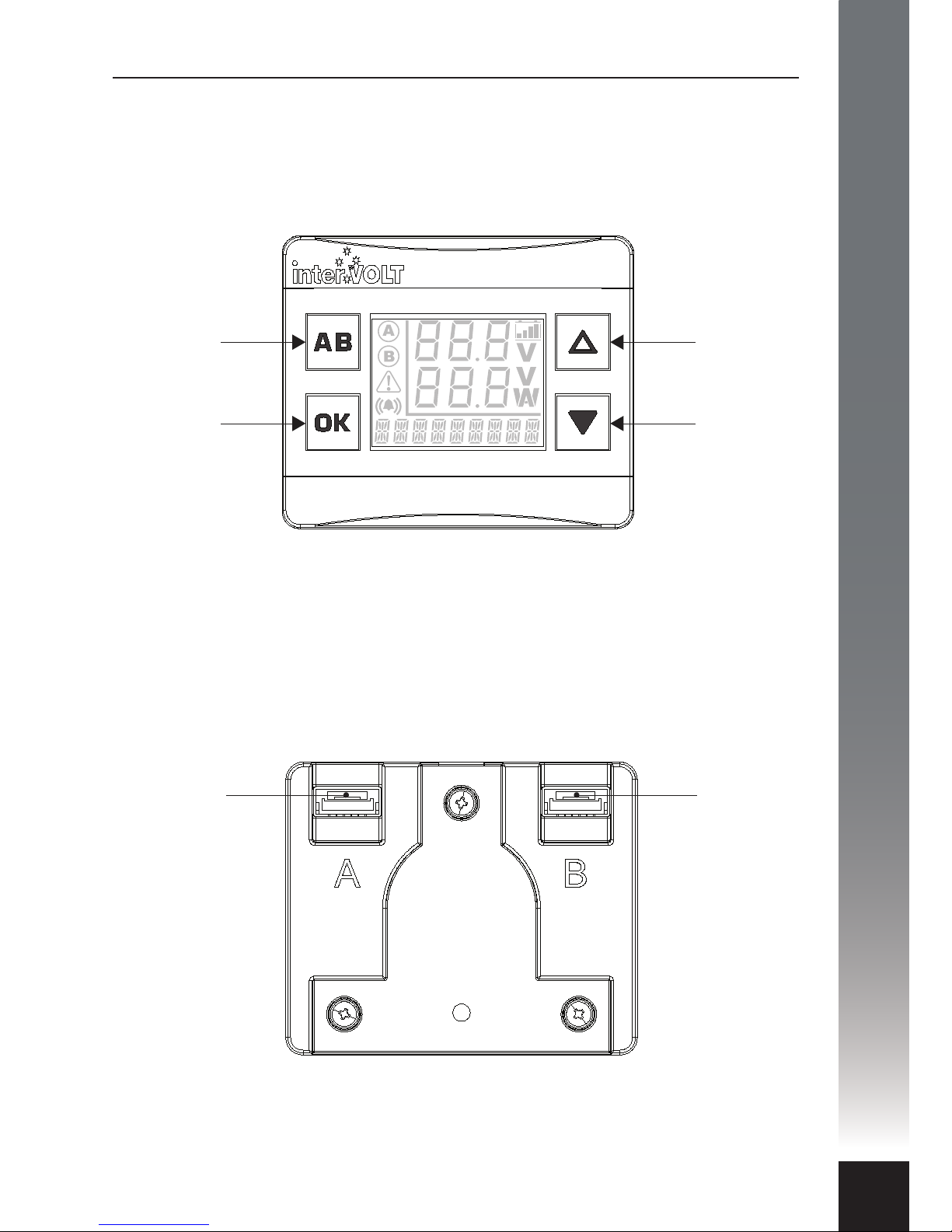
Layout - Remote Display
‘DOWN’ SELECTION
OR LOW
BRIGHTNESS
CONTROL. ALSO
USED TO TURN OFF
BACKLIGHT.
‘UP’ SELECTION
OR HIGH
BRIGHTNESS
CONTROL.
CONFIRMATION
SELECTION BUTTON.
ALSO USED TO
SWITCH BETWEEN
AUXILIARY AND
MAIN BATTERY.
FOR SWITCHING
BETWEEN TWO
CHARGING DEVICES.
ALSO USED AS
BACK AND EXIT
BUTTON.
Front View
Back View
CHARGING
DEVICE
INPUT
A
CHARGING
DEVICE
INPUT
B
Note: Images above shown approximately actual size.

FUNDAMENTALS
10
interVOLT Model
DCC1225ACD
Battery to Battery
Charging Device
12VDC - 12VDC
25 Amps max.
+IGNITION SWITCH SUPPLY
FUSE
12V
AUX
FUSE
12V
MAIN
FUSE
DCC DISPLAY
SOLAR
PANEL
OPTIONAL
IGNITION
SWITCH
TO AUXILIARY
EQUIPMENT
TO
ENGINE
Standard Wiring Diagram

FUNDAMENTALS
11
12V
AUX 2
FUSE
interVOLT Model
DCC1225ACD
Battery to Battery
Charging Device
12VDC - 12VDC
25 Amps max.
12V
AUX 1
FUSE
FUSE
interVOLT Model
DCC1225ACD
Battery to Battery
Charging Device
12VDC - 12VDC
25 Amps max.
12V
MAIN
FUSE
OK
DCC DISPLAY
DCC PRO ADCC PRO B
TO AUXILIARY
EQUIPMENT
TO
ENGINE
TO AUXILIARY
EQUIPMENT
Wiring using two Charging Devices

INSTALLATION
12
Planning the installation
IMPORTANT: In order to ensure safety, high performance and long life the
DCC Pro should only be installed by a suitably qualied tradesperson.
The DCC Pro consists of three main components, the Charging Device, the
Remote Display and the Data Cable which connects the two. Due to the rugged
design the Charging Device can be mounted in the vehicle’s engine bay and the
Remote Display in the cabin. The installation of these components is covered in
the next few pages.
Plan the installation according to the location of the main and auxiliary
batteries. The Charging Device can be situated anywhere in the circuit (subject
to using the appropriate cable size) and does not need to be located directly
next to either battery. Please consider the number of cables required when
planning the install as the location could result in extra wiring. For example if
the DCC Pro is required to charge a battery in a caravan it may be better to
mount the Charging Device in the caravan itself rather than the vehicle but this
may depend on where the Remote Display needs to be located.
Consideration should be given to the wiring layout. The DCC Pro has been
designed so that cables can enter the device from any direction, even from one
side only, without having to cross over. Crimp terminals are recommended over
soldered lugs and should be terminated to automotive quality standards.
Incorrect or poor crimping is not only a mechanical issue (wire separating from
terminal) but will also cause voltage drop and potential overheating of the
conductor as a result. Using the correct wire size for the application is
imperative. The table on page 14 details the correct conductor size according to
the run length.
For complete protection it is necessary to fuse each positive conductor. The fuse
should be installed as close as possible to the power source. Fusing is required
to protect the vehicle in the event of a short circuit – a cable coming o a
terminal and contacting the chassis for example. The DCC Pro itself is fully
protected by a range of internal protection devices. The fuse should be rated
according to the load and should be no greater than the maximum current
rating of the cable being used.
NOTE: All wiring should be terminated and routed but not connected to
the Charging Device at this time. In order to congure the device the
connection must be made in conjunction with the set-up steps depicted on
pages 18–23.
INSTALLATION
13
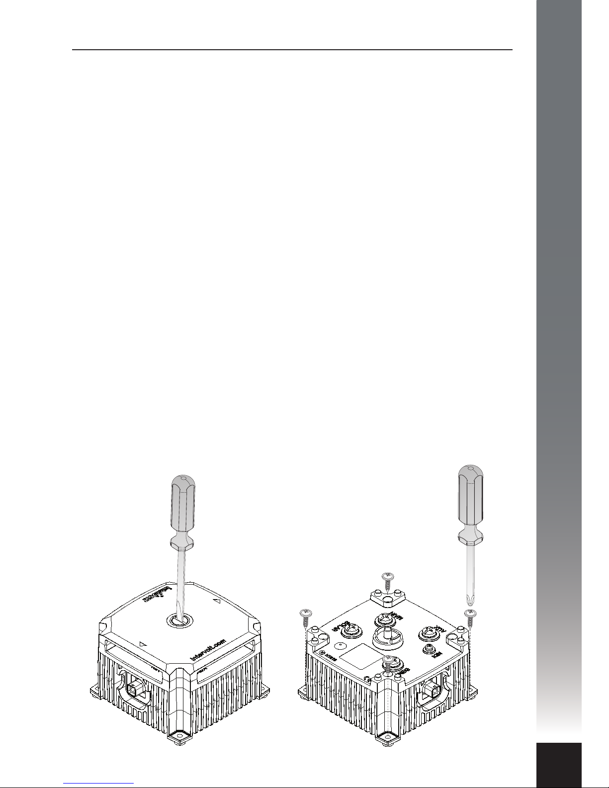
Installing the Charging Device
The DCC Pro Charging Device has been designed to cope with arduous
conditions and can be installed in the vehicle’s engine compartment. Care must
be taken when performing the installation to ensure performance, longevity and
of course, safety. Installing the device too close to a turbocharger for example
may not only force the device into thermal shut down but could also result in
catastrophic failure.
Select a suitable location where the Charging Device can be mounted ensuring
adequate ventilation to the heatsink ns, free from excessive vibration and heat.
Blocking the heatsink ribs could cause thermal shutdown. The electronics are
enclosed in a sealed housing however the device, where possible, should be
installed in a protected environment. The Charging Device is NOT designed to
be installed in a location where water can regularly ‘short’ between the
terminals.
As it is of solid state design, the Charging Device can be mounted in any position
vertically or horizontally. It should be oriented so that the LED Glow Ring
indicator is clearly visible to the installer/operator. It must be installed on a hard
at surface – not an upholstered or insulated surface. Ensure at least 30mm of
clearance all around from any other equipment.
The Charging Device should be xed with appropriate fasteners ensuring all four
anchor holes are utilised. The mounting hole diameter is 4.5mm and it is
recommended that an M4 fastener installed into a rivet nut or with a locking nut
is the best solution.
NOTE: Remove the terminal cover
before using any tools to fasten the
Charging Device in position.

INSTALLATION
14
Wiring the Charging Device
In a standard installation, the Charging Device should be wired according to the
schematic on page 10. A standard installation consists of a Charging Device and
Remote Display. If two Charging Devices are being installed please see page 11
for the alternate schematic.
Using the correct cable size for the job is paramount to performance and safety.
Please refer the table below for the minimum recommended cable size (cross
section) required in order to prevent voltage drop.
All cable lugs must be properly terminated using appropriate tooling in
order to prevent poor contact which can result in overheating of the stud.
An example of the correct method of termination is depicted below.
There are four large terminals, one each for the main and auxiliary batteries, one
for the solar panel and one for the common negative connection. These
terminals use a custom M5 threaded fastener with a 6mm diameter shoulder.
A lug with a 6mm diameter hole should be used for terminating these four
cables. There is a single, smaller, ignition terminal utilised when the optional
Ignition Control mode is required. This uses a standard M3 fastener.
The Charging Device terminals are embossed for clarity and labelled as follows:
MAIN (main battery) – 12V main or starting battery connection
AUX (auxiliary battery) – 12V second or auxiliary battery connection
SOLAR (solar panel) – 12V solar panel connection
IGN (ignition switch) – ignition switch connection
NEG (negative) – 0V input for common negative connection
LCD Display Input – for DCC interconnect cable
Cable Run Length Minimum Conductor Size Recommended SAE Equivalent
1-5 Metres 6 mm² 8 B&S/AWG (7.91mm²)
5-9 Metres 10 mm² 6 B&S/AWG (13.56mm²)
COPPER LUG FOR
MAIN TERMINATION
CRIMP LUGS FOR
IGNITION TERMINATION

INSTALLATION
15
Installing the Data Cable
The Data Cable is the communication link between the Charging Device and the
Remote Display. It has a sealed connection at the device end and unsealed
connector at the display end. The Data Cable is tted with a PVC‘clamshell’
protector over the Remote Display connector plug. This is to protect the plug
from damage when being routed into the vehicle cabin.
To install the Data Cable a 10mm
diameter feed through hole must be
drilled in the panel separating the
Charging Device from the Remote
Display (usually the rewall).
The Data Cable must be fed through
the hole from the Charging Device
side as the sealed connector will not
pass through the hole. A rubber
grommet is tted to the cable and
must be utilised to prevent damage
from the sharp edges of the feed
through hole.
After the Data Cable has been routed
through any obstacles, the PVC
protector can be removed. It is
recommended that the protector
only be removed when ready to
plug into the Remote Display.
There are two plastic clips located on
the mounting bracket base. These are
provided for holding the Data Cable
to relieve any strain on the connector
and should be utilised wherever
possible. The Data Cable simply
pushes into the clip in the desirable
position after the connector is
plugged into the socket on the rear
of the Remote Display.
10mm Ø
Connector protector
to remain in place
until ready to plug in
Data Cable
retaining
clips
INSTALLATION
16
Installing the Remote Display
The DCC Remote Display is designed to be installed in the cabin of the vehicle,
on the dash or console. It should be shielded from excessive heat and located
away from direct sunlight if possible. The Remote Display is made up of two
main sub-assemblies, the display housing itself and the mounting base.
Together the two are designed to be xed in a position that is comfortably
viewable and accessible to the operator. A user adjustable ball joint allows for
the housing to swivel through a range of positions to best suit the operator.
A tensioning screw in the centre of the mounting bracket can be utilised to
adjust and maintain the Remote Display in the desired position. This screw
should not be over-tightened.
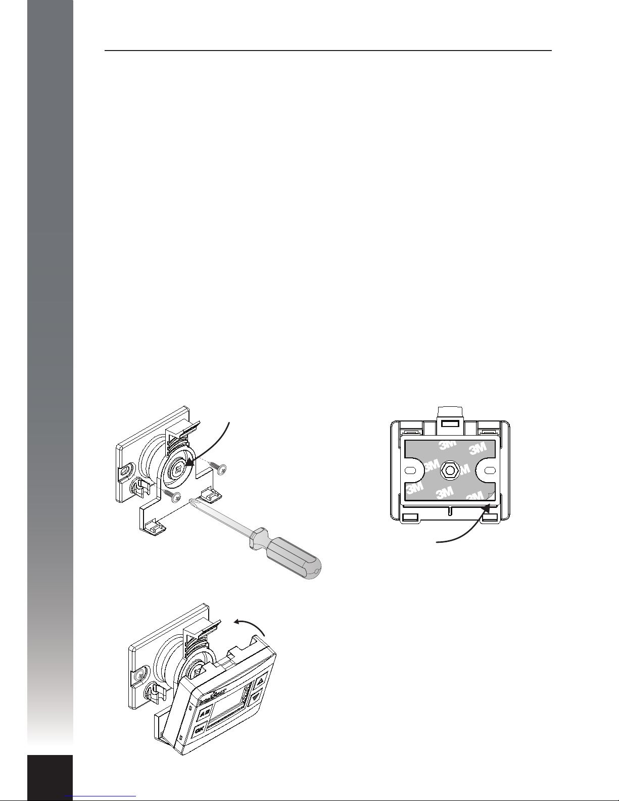
There are two methods provided for xing the mounting base to the surface,
details as follows:
Option A - Screw Fixing:
This method utilises two suitable
fasteners (not supplied) to attach the
mounting base to the surface as per
the diagram below.
Ball Joint
Tensioning
Screw
Option B – Adhesive Fixing:
This method utilises the self-adhesive
foam backing tape to adhere the
mounting base to the surface as per
the diagram below.
Peel o backing
lm to apply
The mounting base is designed to hold
the Remote Display. Place the display
bottom rst into the bracket and
pinpoint the two location tabs provided.
Tilt the display back until the top tab
locates in position with an audible‘click’.
The display can be removed at any time
by pushing the thumb lever gently back
and releasing the housing assembly.

INSTALLATION
17
Connection and Configuration
A step-by-step guide
In some applications, the DCC Pro can be installed and connected straight out
of the box without any changes to the conguration. In other situations it is
necessary to change these defaults, a dierent battery type for example, as
detailed below (see Charging Modes section on page 6 for explanation).
For safety reasons, the battery type and control mode can only be changed
during set-up (conguration mode) before the auxiliary battery is connected.
Of course, these selections can be changed at any time but the auxiliary battery
must be disconnected in order to do so.
In default state the conguration is based on a standard battery to battery
charging installation and assumes the following:
1. The auxiliary battery is a standard lead acid type (sealed or unsealed).
2. The system is not controlled by the vehicle’s ignition circuit. This default
mode is dened as voltage control as opposed to ignition control (see page 6
for an explanation).
The Remote Display is initially used for conguring the Charging Device upon
installation. Most importantly the Remote Display allows for selection of
dierent battery types (chemistries) and the control mode, Voltage Sense or
Ignition Control (see explanation on page 6).
The following options are available for selection:
• Standard Lead Acid – displayed as 1LEAD ACID on the Remote Display
during set-up or SLA in short form.
• Absorbed Glass Mat – displayed as 2 AGM on the Remote Display during
set-up and in short form.
• Gelied Electrolyte – displayed as 3GEL on the Remote Display during
set-up and in short form.
• Lead Calcium – displayed as 4 CALCIUM on the Remote Display during
set-up or LCA in short form.
• Constant Float – displayed as 5 FLOAT on the Remote Display during
set-up and in short form.
The following pages illustrate the step by step conguration process for
installing the Charging Device and Remote Display. If there is a need to
change the battery type and control mode, this process must be completed
in the order depicted for the DCC Pro to operate correctly.

INSTALLATION
18
3
2
1
interVOLT Model
DCC1225ACD
Battery to Battery
Charging Device
12VDC - 12VDC
25 Amps max.
The negative power cable should be
connected to the Charging Device rst.
This should be fastened to the terminal
marked NEG using the special screw
provided. Connect the other end of the
negative to the main battery negative
(recommended) or directly to the
chassis, ensuring the connection has
good contact. Ensure the auxiliary
battery negative is either connected to
the NEG terminal of the Charging
Device or the chassis.
The Remote Display end of the Data Cable
is tted with an unsealed 6-way connector
plug. The plug is tted with a plastic
clamshell to protect it from damage
during installation. The clamshell is
secured with tape and should now be
removed for installation. The plug should
be gently pushed into the mating
connector socket until it‘clicks’into
position. When using one Charging Device
either socket can be utilised.
The Charging Device end of the Data
Cable is tted with a sealed 6-way
connector plug. The plug is marked with
a spot of identifying colour indicating
the top of the connector. The plug should
be gently pushed into the mating
connector socket until it‘clicks’into
position. To check the latch has engaged
gently pull the connector – it should not
move. If there is a need to remove the
connector, please see page 23 for
instructions.
Connect the negative power cable to the Charging Device
Connect the Data Cable to the Remote Display (if utilised)
Connect the Data Cable to the Charging Device
Other manuals for DCC Pro
1
Table of contents
Other intervolt Batteries Charger manuals


