This information is subject to change without prior notice
web: www.intesisbox.com
phone: +34 938047134
IBOX-MBS-DALI
DALI to Modbus Server Protocol Converter
Order Code: IBMBSDAL1280000
Installation Sheet rev.1.2
Intesis Software S.L.U. © 2018
!WARNING
Follow carefully this safety and installation instructions.
Improper work may lead to serious harmful for your health
and also may damage seriously the IntesisBox and/or any
other equipment connected to it.
IntesisBox must be installed by accredited electrician or similar
technical personnel, following all the safety instructions given here and
in accordance always with the country legislation for installation of
electric equipment.
IntesisBox cannot be installed outdoors or exposed to direct solar
radiation, water, high relative humidity or dust.
IntesisBox must only be installed in a restricted access location.
In case of wall mount, fix firmly IntesisBox on a not vibrating surface
following the instructions next.
In case of DIN rail mount fixIntesisBox properly to the DIN rail following
the instructions below.
Mounting on DIN rail inside a metallic cabinet properly connected to
earth is recommended.
Disconnect always power of any wires before manipulating and
connecting them to IntesisBox.
A power supply with an NEC Class 2 or Limited Power Source (LPS)
and SELV rated is to be used.
Respect always the expected polarity of power and communication
cables when connecting them to IntesisBox.
Supply always a correct voltage to power IntesisBox, see details of
voltage range admitted by the device in the technical characteristics
below.
CAUTION: Risk of Explosion if Battery is replaced by an Incorrect Type.
Dispose of Used Batteries according to the instructions. Battery
replacement shall be done by an authorized installer.
CAUTION: The device is to be connected only to networks without
routing to the outside plant, all communication ports are considered for
indoor only.
This device was designed for installation in an enclosure. To avoid
electrostatic discharge to the unit in environments with static levels
above 4 kV, precautions should be taken when the device is mounted
outside an enclosure. When working in an enclosure (ex. making
adjustments, setting switches etc.) typical anti-static precautions
should be observed before touching the unit.
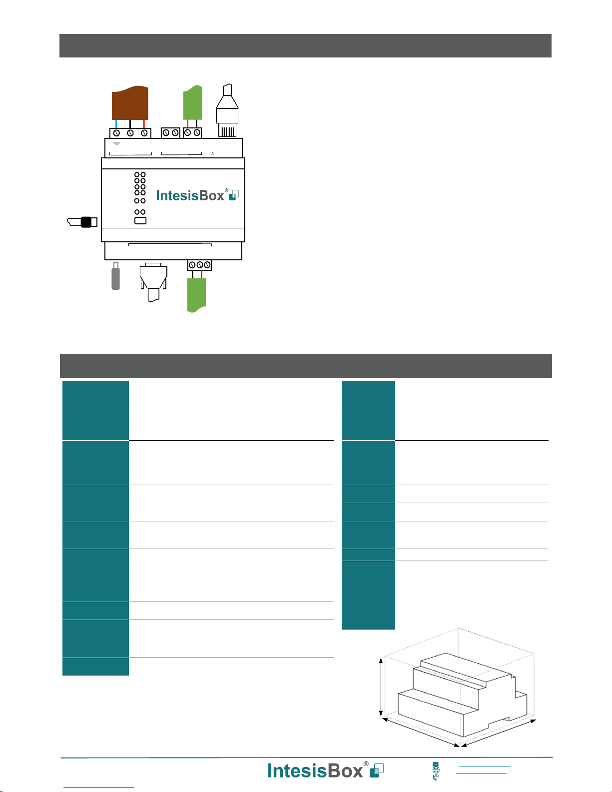
Follow instructions next to properly install the gateway.
Disconnect from mains the power supply before connecting it to
IntesisBox.
Disconnect power of any bus or communication cable before
connecting it to IntesisBox.
Mount IntesisBox on the wall or DIN rail following the instruction given
below, respecting the safety instructions given above.
Connect a NEC Class 2 or Limited Power Source (LPS) and SELV
rated power supply to IntesisBox, respect the polarity if DC power or
Line and Neutral if AC power. Apply always a voltage within the range
admitted by IntesisBox and of enough power (see technical
characteristics).
Circuit-breaker must be used before the power supply. Rating 250V-
6A.
Connect the communication cables to IntesisBox, see details on the
user's manual.
Power IntesisBox and the rest of devices connected to it.
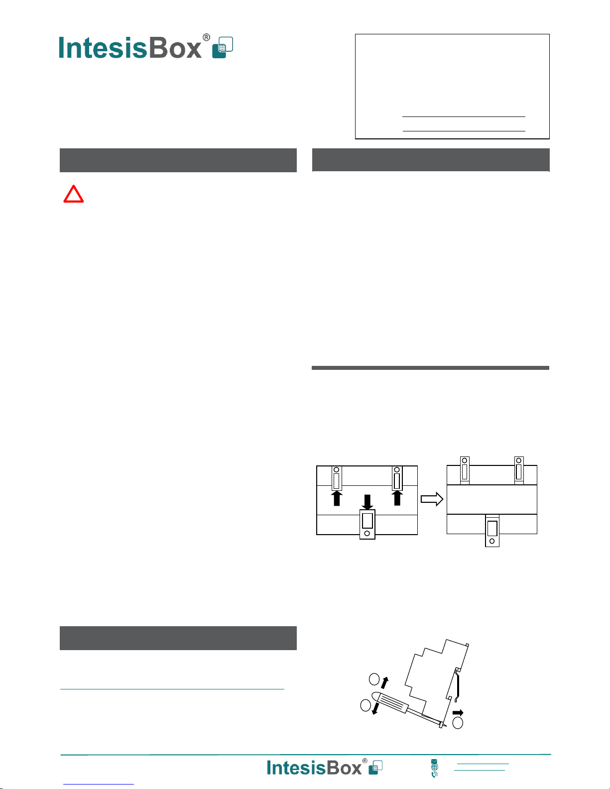
Wall Mount
3. Separate the fixing clips in the bottom of the box, pushing
them to the outside until hear the "click" which indicates that
now the clips are in position for wall mount, see in the figure
below.
4. Use the holes of the clips to fix the box in the wall using
screws. Use the template below for the wall wholes.
Clips in their original position Clips in position for wall mount
(for DIN rail mount)
DIN Rail Mount
With the clips of the box in their original position, insert first the box
in the upper edge of the DIN rail and later insert the box in the
down part of the rail, using a small screwdriver and following the
steps in the figure below.
The model and serial numbers are located on the rear
of the gateway. Record these numbers in the space
provided below. Refer to them whenever you contact
upon your gateway dealer or support team regarding
this product.
Model No.
Use the Configuration Tool to configure the gateway.
See instructions to download and install the latest version at:
http://intesisbox.com/intesis/software/intesisbox_maps_installer.exe
Use the Ethernet connection or the Console Port (mini USB type B
connector included) to get communication between the gateway and
the configuration tool.
Follow the instructions of the user's manual for more details.