Intiel TD-3.3 User manual

Programmable Differential Thermostat
TD-3.3
User’s Manual
tel.:00359 596 333 66 ||| fax:00359 596 325 80 ||| [email protected] ||| www.intiel.com
9 Peter Beron Str, Pomorie 8200, Bulgaria

2
І. Application
Differential Thermostat DT-3.3 is used for a domestic hot water preparation, where the
heating of the water tanks is provided in a combined way, by solar panels and electrical
heating elements. It is designed to control the operation of one or two circulation pumps,
installed in the water circuit between the solar panels and water tank serpentine,
thus regulating the heat exchanging between them.
II. Functionality
DT-3.3 has an ability to control two main types of installations for a domestic hot
water preparation by means of solar or heating systems depends on the selected program.
2.1 Systems equipped with one water tank (default program) –the differential
thermostat follows the temperature of the solar panel (T1), the temperature of the
lowest part of the water tank (T2) and the temperature of the upper part of the
water tank (T3).
2.2 Systems equipped with two water tanks –the differential thermostats follows
the solar panel temperature (T1), the temperature of the lowest part of water tank 1 (T2)
and the temperature of lowest part of water tank 2 (T3). The heating of water tank 1 is
with a higher priority than water tank 2
III. Operation
The Thermostat is equipped with three temperature sensors, mounted respectively at
the water tank (tanks) and at the solar panels. During its operation the thermostat monitors
the following parameters:
3.1. dT, ∆t –adjusted and current (real) difference between the water tank and solar
panel temperatures. dТ can be adjusted in the range of 2 up to 20°С.
The default setting is 10°С
3.2. Tzad (W) –assigned temperature level of the water tank to which it can be heated
from the solar panels. The temperature can be adjusted in the range between 30 and 80°С.
The default setting is 60°С.
3.3. Tzad1(W1) –assigned temperature in the second water tank in systems with 2
water tanks or an assigned temperature at the upper part with systems with one water tank.
The default setting is 60°С.
3.4. Tbmax –critical maximum allowed water tank temperature. It can be adjusted in
the range between 80 and 100 °С. The default setting is 90°С.
3.5. Tbmin –minimum water tank temperature bellow which the solar panel
defrosting is being stopped. It cannot be adjusted. The default setting is 20°С.
3.6. Tcmin –minimum temperature level of the solar panel. It can be adjusted in the
range between 25 and 50 °С. The default setting is 40°С.
3.7. Tcmax –maximum allowed temperature of the solar panel. It can be adjusted in
the range between 90 and 110°С. The default setting is 110°С.
3.8. Tdef –defrost temperature level of the solar panel. It can be fixed in the
range between (-20) up to (+10)°С. The default setting disables this function “- -“.
3.9. Tvmax –maximum allowed water tank temperature at which an emergency
drainage of the water tank can be started by means of relay output 3. It can be adjusted in
the range between 50 and 95°С. The default setting is 95°С

3
- When one of the temperatures is grater than +120°C on the digital display is being
indicated “Hi”.
- When one of the temperatures is lower than -20°C on the digital display is
being indicated “Lo”
Differential Thermostat DT-3.3 operation depends on the temperature sensor states, as
follows:
Installations equipped with one water tank
А) Normal operation
The circulation pump is being switched on and the water tank heating is being started
if the temperature at the lowest part of the water tank is lower than Tzad and there
is a positive difference ∆t between the solar panel and lowest part or the water
tank temperature, grater than the assigned one dТ (Т1-Т2> dТ). The circulation pump is
being stopped (relay output 1) if during water tank heating ∆t is being decreased, thus
after ∆t gets equalized with the assigned one dT
The heating of the water tank at the above mentioned conditions is going until
the water tank temperature at its lowest part is getting the same with the assigned one
Tzad. Afterwards the pump is being switched off and the heating is being stopped.
If under the above mentioned conditions the solar panel temperature is going
down bellow Tcmin, then the circulation pump operation will be stopped by force,
despite of conditions ∆t>dТи Т2<Tzad could be available.
In case the solar panel temperature falls bellow Tdef, the circulation pump is being
switched on by force, never mind it has been switched off due to solar panel temperature
decreasing bellow Tcmin. (only in case the defrost option is activated)
If during the previous mentioned operation mode the water tank temperature falls
down bellow Tbmin, then the circulation pump is being switched off as the solar
panel defrosting is being stopped.
If the water tank temperature at its upper part T3 is lower than the assigned
one Tzad1, then the electrical heating elements operation is being allowed until
Tzad1 is being reached. (relay output 2), but only in case there are no conditions
for circulation pump operation.
В) Emergency operation
If during water tank heating, the solar panel temperature exceeds Tcmax, the
circulation pump is being started by force in order to cool the solar panel. The
previous mentioned will be fulfilled despite of the water tank temperature at its
lowest part T2 could exceeded Tzad (relay output 1).
If during the above mentioned emergency mode the water tank temperature at
its lowest part reaches the critical maximum value Tbmax, then the circulation
pump is being switched off never mind it could reflect to solar panel overheating. Thus
the water tank temperature has a higher priority than the solar panel one.
When the water tank temperature at its upper part T3 exceeds Tvmax a valve is being
switched on in order to drain the hot water of the water tank (relay output 3).

4
Installations equipped with two water tanks
А) Normal operation
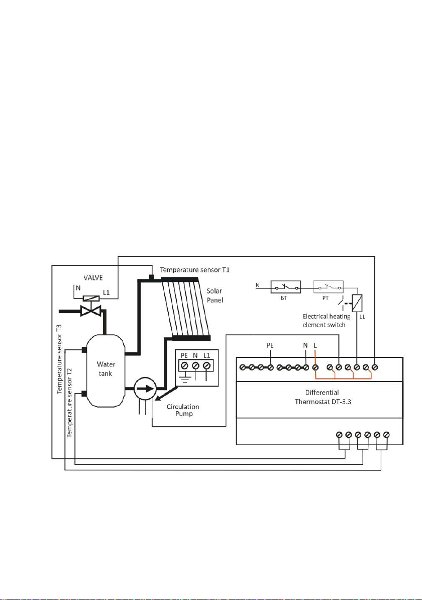
- The circulation pump 1 is being switched on and the heating of the water
tank is being started by means of the solar panels if temperature T2 in water tank 1 is
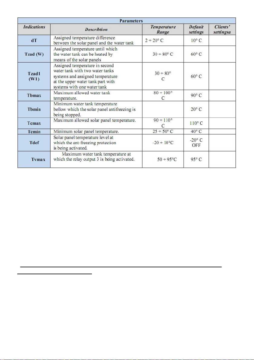
lower than the assigned one Tzad and if there is a positive difference ∆t between the solar
panel and the water tank temperatures grater than the assigned dТ (Т1-Т2> dТ),
The circulation pump is being stopped if during water tank heating ∆t is being
decreased, thus after ∆t gets equalized with the assigned one dT.
The heating of the water tank at the above mentioned conditions is going until the
water tank temperature is getting the same with the assigned one Tzad. Afterwards
the pump is being switched off and the heating is being stopped (relay output 1).
- when water tank 1 reaches its assigned temperature, then the operation of circulation
pump 1 is being stopped and the heating of the second water tank is being started
as circulation pump 2 is being switched on. In this case circulation pump 2 will be started
in case temperature T3 in water tank 2 is lower than Tzad1 and there is a positive
difference ∆t between solar panel and water tank, grater than the assigned one
temperatures dТ (Т1- Т3>dT) (relay output 1 and 2).
- the operation of circulation pump 2 is being stopped in case of reaching Tzad1,
equalizing ∆t with dТ or with decreasing of T2 concerning water tank 1 bellow Tzad.
In the last case after circulation pump 2 is being switched off circulation pump 1 is being
switched on for heating of water tank 1.
-If under the above mentioned conditions the solar panel temperature is going down
bellow Tcmin, then both circulation pumps operation will be stopped by force, despite of
conditions ∆t>dТ and Т2<Tzad, Т3<Тzad1 could be available. (relay output 1 and 2)
- in case the solar panel temperature falls bellow Tdef, circulation pump 1 is being
switched on by force, never mind it has been switched off due to solar panel
temperature decreasing bellow Tcmin. (only in case the defrost option is activated)
- if during the previous mentioned operation mode water tank 1 temperature falls down
bellow Tbmin, then the circulation pump is being switched off as the solar panel
defrosting is being stopped.
В) Emergency operation
-if during water tanks heating, the solar panel temperature exceeds Tcmax, the
circulation pumps are being started by force in order to cool the solar panel. The previous
mentioned will be fulfilled despite of temperatures T2 and T3 of the water tanks
could exceed Tzad and Tzad1 (relay output 1 and 2).
- if during the above mentioned emergency mode the water tank temperatures reach
the critical maximum value Tbmax, then the circulation pumps are being switched
off never mind it could reflect to solar panel overheating. Thus the water tank temperature
has a higher priority than the solar panel one.
- when temperature T3 in water tank 2 exceeds Tvmax a valve is being switched on in
order to drain the hot water of the water tank (relay output 3).

5
ІV. Front panel indications
On the front panel are located the control elements and programming. These are
two line LCD display, seven light indications and three buttons –button up, button down
and button ”SET”.
The front panel vision is shown at Figure 1 bellow.
4.1 Light indication 1 –shows the operation of circulation pump 1
4.2 Light indication 2 - shows the operation of circulation pump 2 (in case two water
tanks are installed) or heating of the water tank by means of electrical heating
elements.
4.3 Light indication 3 –shows switched on valve for hot water draining.
4.4 Light indication 4 –shows emergency situation with the solar panel, for example a
maximum solar panel temperature is being reached or a defrost protection is activated.
4.5 Light indication 5 –show an emergency situation, the temperature in water tank 1
has being reached the maximum allowed water tank temperature Tbmax.
4.6 Light indication 6 –show an emergency situation, the temperature in water tank 2
has being reached the maximum allowed water tank temperature Tbmax.
4.7. Light indication 7 –shows that the unit is in a “Vacation” regime.
After connection of the power supply the thermostat goes into an initial mode
as it shows the solar panel and water tank/tanks temperatures.
Figure 1
V.Programming
5.1 Entering the thermostat menu
By pressing and holding the "SET" button for more than 3 seconds.
With the up and down to navigate forwards and backwards in the menu. Change the
selected item by pressing of a button SET (Figure 1). A when the value is changed after
pressing the button SET value start flashing, changing it is done by pressing up or down.
Confirm the selected value - again with SET.
Vacation Regime - Mode is designed for cases where tanks is not used for a long
time. When activated, the temperature of the water heater is set at 40 ° C and the inclusion
of electric heaters is terminate. Pumps turns as necessary in order avoid overheating the
water heater or the panel.
Save & Exit –Save Settings and exit from the menu.

6
Menu Password - Allows access to the menu to be restricted by password. When
selecting enable, the option is activated. You can change the password from the following
setting - Renew Password. The default password (the one that the manufacturer supplies
the controller) is 000. After Menu Password is enable, to enter the menu you must enter
the correct password. Press the SET button and the up, down select the appropriate
number, press the SET button again to select the other two digits of the password. If the
password is entered incorrectly three times, the controller returns to working condition.
If within 5 seconds not start entering the password, access the menu, but with limited
rights, You can browse the selections and parameters, they can not be changed, except for
the vacation regime.
In Menu Password - disable, menu access does not require a password.
If a period of 30 sec. no buttons are pressed, it should automatically exit the menu, as the
changes are not saved in memory. In this case they will be valid until it is stopped
power.
One of Two water tanks Anti-freezing protection
Figure 2
VI. Wiring
The wiring of the thermostat includes connection of the temperature sensors, power
supply, controlled circulation
pump, electrical heating
elements and a valve
according Figure 3. The
temperature sensors are Pt-
1000 non-polar ones. In case
of necessity the connection
cables of the sensors could be
prolonged as the total
resistance of both cores of the
cable will be observed –an
indication sensibility of
1°С/4Ω. The recommended
cable length which does not
affect the measurement
precision is up to 100m.

7
Terminals 1 and 2 are inputs for solar panel temperature sensor T1. Pt-1000 sensor is to
be connected to those terminals. Terminals 3 and 4 are inputs for water tank 1
temperature sensor T2. Pt-1000 sensor is to be connected to those terminals. Terminals
5 and 6 are inputs for water tank1/water tank2 temperature sensors T3. Pt-1000 sensor
is to be connected to those terminals.
To terminals 13, 17 and 21 are to be connected a phase, neutral and protection ground
of the grid. To terminals 11, 9 and 7 are to be connected respectively circulation
pump 1, circulation pump 2/electrical heating elements and a valve. A phase (L1)
appears at terminals 12, 10 and 8, when it does not at terminals 13, 17 and 21, and an
opposite.
VII. Hydraulic connections
A) Systems equipped with one water tank. The water tank heating is provided
by means of solar panel and electrical heating elements
БТ –blocking thermostat
РT –operation thermostat
Фиг.3
Figure 3

8
B) Systems equipped with two water tanks. The water tank heating is provided by
means of solar panels.
VIII. Technical data
Supply voltage: 230V / АС / 50-60Hz
Maximal rated current: 7А / 250V / AC / 50-60Hz
Outputs: 3 standard relays (changeover contacts)
Switch-on difference: ∆T 2…20° С adjustable
Sensors: 3 temperature sensors Pt1000 (-50° до +200°C)
Sensor current: 2.6 mA
Range of temperature measuring: from -20 up to +120°С
Digital display: Two lines LCD
Measurement precision: 1°С
Humidity: 0-80%
Protection: IP20

9
Warranty
The warranty period is 24 months following the purchase date of the unit or its
installation by an authorized Engineering Company, but not exceeding 28 months
after the production date. The warranty is extended to the malfunctions that occur during
the warranty period and are result of the production reasons or defective used parts.
The warranty does not relate to malfunctions corresponding to not-qualified
installation, activities directed to the product body interference, not regular storage or
transport.
The repairs during the warranty period can be done after correct filling of the
manufacturer warranty card
Other manuals for TD-3.3
1
Table of contents
Other Intiel Thermostat manuals
Popular Thermostat manuals by other brands

TCS
TCS US4050 installation manual

Johnson Controls
Johnson Controls Hx3 S1-THXU430W User's information manual

American Standard
American Standard Moments R510 Features & dimensions

EPH Controls
EPH Controls CDTP2 operating instructions

Thermo Pride
Thermo Pride Premiere Series Specifications

Honeywell
Honeywell T6360B1036 GUIDE TO THE USE

Honeywell
Honeywell T451 Product data

Ingersoll-Rand
Ingersoll-Rand TRANE NEXIA TZEMT500BB32MAA Installation and user instructions

OJ Electronics
OJ Electronics OJ Microline ICD3-1999 user manual

Jackson Systems
Jackson Systems Comfort System T-21-P user manual

olympia electronics
olympia electronics BS-812 manual

Tellur
Tellur TLL331151 user manual