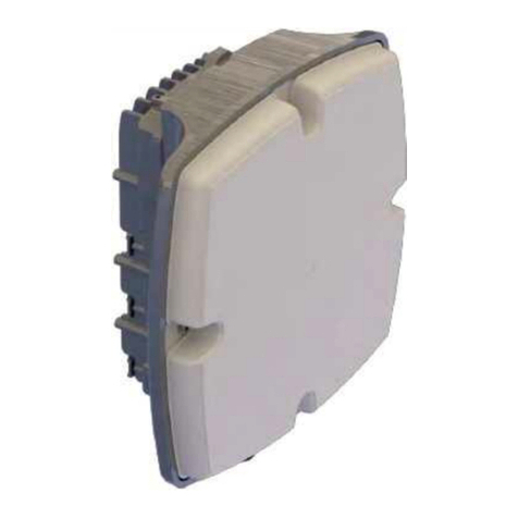
Intracom netMod User manual

netMod
user's manual

INTRACOM - Documentation Section
All copyright and industrial rights in this document and in the technical
knowledge it contains are owned by INTRACOM S.A. and/or the third parties
rightfully concerned.
No part of this document nor any data herein shall be disclosed, reproduced
or used for any purpose whatsoever without the prior written approval of
INTRACOM S.A.
Drawings and specifications are subject to change without prior notice.
All trademarks are the property of their respective holders.
Printed in Greece.
INTRACOM - Documentation Section
ÉÍÔRACOM S.A., 2003

User’s Manual of netMod Network Termination Unit
Contents
INTRODUCTION................................................................................................................. 6
An Introduction to ISDN...............................................................................................................6
netCon ...........................................................................................................................................7
netCon+ .........................................................................................................................................7
netMod...........................................................................................................................................7
FAMILIARIZATION WITH netMod NETWORK TERMINATION UNIT .............................. 9
Installation of netMod ................................................................................................................10
Switch Settings...........................................................................................................................13
Indicators ....................................................................................................................................14
netMod’s Functionality in Case of Emergency Operation......................................................15
DTE port selection on emergency ............................................................................................15
U-line Connection.......................................................................................................................16
Terminal Devices Connection ........................................................................................ 17
Connecting Analogue Devices..................................................................................................17
Connecting an ISDN Device ......................................................................................................18
Connecting a Personal Computer.............................................................................................19
ISDN SERVICES............................................................................................................... 20
Detailed Description and Use of Supplementary Services.....................................................22
1. Multiple Subscriber Number (MSN) ..........................................................................22
2. Call Waiting (CW) .....................................................................................................23
3. Call Hold and Enquiry Call (CH) ...............................................................................24
4. Three Party Conference (3PTY) ...............................................................................24
5. Calling Line Identification Presentation.....................................................................25
5.1. Calling Line Identification Presentation (ON HOOK CLIP)....................................25
5.2. Setting the Own Number .......................................................................................25
5.3. Calling Line Identification Presentation (OFF HOOK CLIP or CLIP on CW).........25
6. Calling Line Identification Restriction (CLIR) ............................................................26
7. Connected Line Restriction (COLR) .........................................................................26
8. Malicious Call Identification (MCID)..........................................................................26
9. Advice Of Charge During the call (AOC-D)...............................................................27
10. Closed User Group (CUG)........................................................................................27
11. Terminal Portability (TP) ...........................................................................................28
12. Call Diversion............................................................................................................28
12.1. Call Forwarding Unconditional (CFU)..................................................................29
12.2. Call Forwarding on Busy (CFB)...........................................................................30
12.3. Call Forwarding on No Reply (CFNR) .................................................................31
12.4. Call Forwarding Unconditional to Voice Mail.......................................................32
13. Completion of Calls to a Busy Subscriber (CCBS) ...................................................32
1

User’s Manual of netMod Network Termination Unit
Detailed Description and Use of Additional Services ............................................................ 33
1. Functional / Keypad Protocol ................................................................................... 33
2. Hot Line (HL) ............................................................................................................ 33
3. Delayed Clear Back.................................................................................................. 34
4. Incoming Call Management...................................................................................... 34
5. Hook Flash Detect Time for Analogue Adapters ...................................................... 34
6. Distinctive Ringing.................................................................................................... 35
7. Polarity Reverse ....................................................................................................... 35
8. Call Pickup ............................................................................................................... 36
SUPPLEMENTARY SERVICES AND TERMINAL DEVICES .......................................... 37
Connecting a Terminal Device to the S-bus ............................................................................. 37
Connecting a Videophone ........................................................................................................ 38
Connecting a FAX or MODEM to the Analogue Ports .............................................................. 38
Communication with an ISDN MODEM .................................................................................... 39
CONNECTING TO A PC................................................................................................... 40
Installation of netMod................................................................................................................ 40
Installation Procedure ............................................................................................................... 40
Installation Completion ............................................................................................................. 43
Configuring netMod with the netMod Task Bar Utility (nMtsk).............................................. 45
RVS-COM Lite............................................................................................................................. 46
RVS-COM Lite in brief...........................................................................................................46
CONNECTING TO THE INTERNET ................................................................................. 47
Required Settings ..................................................................................................................... 47
Connecting to the Internet using PPP or ML-PPP Protocol...................................................... 51
FIRMWARE UPDATE....................................................................................................... 54
Software Update Instructions ................................................................................................... 54
COMMUNICATION BY OTHER MEANS.......................................................................... 56
Transmission using a PPP Protocol ......................................................................................... 56
Transparent Modes................................................................................................................... 58
Voice Transparent Mode ....................................................................................................... 58
PPP Transparent Mode......................................................................................................... 58
Data Transparent Mode ........................................................................................................ 59
netMod and AO/DI................................................................................................................. 59
AT COMMANDS............................................................................................................... 61
AT COMMANDS Definition ........................................................................................................ 61
ML-PPP Settings using the AT COMMANDS ........................................................................... 61
Basic “AT” Command Set......................................................................................................... 62
Extended “AT&” Command Set................................................................................................ 64
Extended AT! Command set (AO/DI - X.25 Functionality)...................................................... 65
Basic S-Registers “ATSN=X”.................................................................................................... 66
2

User’s Manual of netMod Network Termination Unit
Extended S-Registers “ATSN=X” .............................................................................................66
Permanent Storage of the S-Registers Settings......................................................................71
Supplementary Services using AT Commands.......................................................................73
1. Multiple Subscriber Number (MSN) ..........................................................................73
2. Call Waiting (CW) .....................................................................................................74
3. Calling Line Identification Presentation (CLIP) .........................................................75
4. Calling Line Identification Restriction (CLIR) ............................................................76
5. Connected Line Restriction (COLR) .........................................................................76
6. Advice Of Charge During the call (AOC-D)...............................................................77
Additional Services using AT Commands ...............................................................................78
1. Delayed Clear Back ..................................................................................................78
2. Activation of Functional / Keypad Protocol ...............................................................78
CREATION OF A PASSIVE BUS (S-BUS)....................................................................... 79
Short Passive Bus 1..................................................................................................................79
Short Passive Bus 2..................................................................................................................80
Extended Passive Bus ..............................................................................................................81
Point-to-point Connection..........................................................................................................82
TECHNICAL CHARACTERISTICS................................................................................... 83
MALFUNCTION DETECTION AND TROUBLESHOOTING ............................................ 85
3

User’s Manual of netMod Network Termination Unit
List of Figures
Figure 1: The basic rate access connection (BRA) between the subscriber and the ISDN
network................................................................................................................. 6
Figure 2: Connections of NT1 type devices......................................................................... 8
Figure 3: netMod’s mounting points .................................................................................. 10
Figure 4: netMod’s Connections........................................................................................ 11
Figure 5: netMod’s switch settings on the motherboard card ............................................ 13
Figure 6: netMod’s LEDs................................................................................................... 14
Figure 7: U-line connector ................................................................................................. 16
Figure 8: The connection points of plain analogue devices to RJ-11 jacks ....................... 17
Figure 9: The connection points of ISDN devices to RJ-45 jacks...................................... 18
Figure 8: Connecting a PC ................................................................................................ 19
Figure 11: Short passive bus 1 connection ....................................................................... 79
Figure 12: Short passive bus 2 connection ....................................................................... 80
Figure 13: Extended passive bus connection.................................................................... 81
Figure 14: Point-to-point connection.................................................................................. 82
Figure 15: S-bus termination ............................................................................................. 82
4

User’s Manual of netMod Network Termination Unit
Terms and Abbreviations
2B1Q 2 Binary 1 Quaternary Line Code
AMI Alternate Mark Inversion
BAP Bandwidth Allocation Protocol
BACP Bandwidth Allocation Control Protocol
BOD Bandwidth on Demand
Bps Bits per second
BRA Basic Rate Access
DTE Data Terminal Equipment
DCE Data Communications Equipment
FSK ` Frequency Shift Key
HDLC High Level Data Link Control
ISDN Integrated Services Digital Network
ISP Internet Service Provider
kbps Kilobits per second
ML-PPP Multilink PPP
MSN Multiple Subscriber Number
NT1 Network Termination 1
PPP Point-to-Point Protocol
PC Personal Computer
5

User’s Manual of netMod Network Termination Unit
INTRODUCTION
An Introduction to ISDN
ISDN (Integrated Services Digital Network) is a digital network capable of providing the
end user with high speed data, voice and image transmission at the same time. A way of
accessing the network, is by using the (Basic Rate Access or BRA or 2B+D)
communication protocol which supplies three channels to the subscriber. Two of these
channels are 64kbps channels (B-channels) used for the transmission of voice or / and
data, while the third one is a 16kbps channel (D-channel), used for signalling transmission
between the ISDN Exchange and the Network Termination NT1.
Figure 1: The basic rate access connection (BRA) between the subscriber and the
ISDN network
The connection of a subscriber terminal device to the network requires an intermediate
device, called Network Termination 1 or NT1. The device is installed at the subscriber
side and is connected to the ISDN Exchange via a simple 2-wire line, known as U-line
(Figure 1). The U-line transfers the digital signal that corresponds to the 2B+D channels.
Different types of terminal devices can be connected to the NT1 (ISDN or plain analogue
terminals). In order to cover up the different subscriber’s needs, INTRACOM offers the
following types of Network Termination units:
• netCon
• netCon+
• netMod
6

User’s Manual of netMod Network Termination Unit
netCon
netCon offers to the subscriber the possibility of connecting up to 8 ISDN terminal devices
to the ISDN network. The connection is via a 4-wire cable, known as the S-bus. netCon
has two RJ-45 jacks used for the connection of the ISDN terminal devices to the S-bus. Up
to 8 ISDN terminal devices can be connected as described in the paragraph “Connecting
an ISDN Device” on page 18.
netCon+
netCon+ besides offering the possibility of connecting ISDN terminal devices to the ISDN
network, also offers the possibility of connecting plain analogue devices (like analogue
telephones, FAX G3, analogue modems, etc.). The connection of plain analogue devices
is made via the two analogue ports (RJ11-jacks), while at the same time the connection of
up to 8 ISDN terminal devices is made via the two RJ-45 jacks of the S-bus (see
paragraphs “Connecting Analogue Devices” and “Connecting an ISDN Device”, on page
17 and 18 respectively).
netMod
netMod, besides offering the possibilities of connecting ISDN terminal devices and plain
analogue devices to the ISDN network, also offers the possibility of connecting a Personal
Computer (PC) to the Internet (or similar networks) without using any extra equipment.
The connection of up to 8 ISDN terminal devices is made via the S-bus, while the plain
analogue devices are connected through the two analogue ports and the Personal
Computer (PC) through the asynchronous serial port (RS232) or the USB port, (see
paragraphs “Connecting Analogue Devices”, “Connecting an ISDN Device” and
“Connecting a Personal Computer”, on pages 17, 18 and 19 respectively).
7

User’s Manual of netMod Network Termination Unit
The connection of NT1 type devices to the ISDN exchange and to the subscriber terminal
devices is shown in Figure 2.
Figure 2: Connections of NT1 type devices
Figure 2 clearly shows (shade levels) that netMod surpasses the potentiality of netCon+,
and netCon+ surpasses the potentiality of netCon.
8

User’s Manual of netMod Network Termination Unit
FAMILIARIZATION WITH netMod NETWORK TERMINATION UNIT
netMod is equipped with:
• 2×RJ-45 jacks for ISDN terminal devices connection. These jacks are the S-Interface
(S-bus) ports of the device.
• 2×RJ-11 jacks for analogue terminal devices connection. These jacks are the
analogue ports (ab1 and ab2) of the device.
• an RJ-11 jack for two wire U-line connection.
• a DB-9 connector to connect the personal computer (PC). This connector is the serial
port RS232 of the device.
• a USB receptacle to connect the personal computer (PC).
• a power supply cable of 230VAC.
netMod offers the following functions and capabilities:
• transmission of data to the serial port with rates up to 230.4 kbps, to and from the
connected personal computer (PC), for point-to-point connections or Internet access.
Note that most of the personal computers do not support rates of 230.4kbps on their
serial port, so the rate is limited to 115.2kbps. In this case a peripheral card is added to
the PC, in order to support the desired rates of 230.4kbps.
• transmission of data to the USB port Ver. 1.1 compatible (with rates up to 12Mbps) for
full availability of the bandwidth of 128kbps.
• interoperability with any operating system (Linux, Macintosh, Windows’
95/98/NT/ME/2K/XP etc.) using non-proprietary protocols.
• PPP (Point-to-Point Protocol) synchronous to asynchronous conversion for 64kbps
communication.
• B-channels bundling with Multilink-PPP support up to 128 kbps.
• PPP over X.25 over D channel protocol for Always On/Dynamic ISDN (AO/DI) use and
X.25 applications.
• transparent operation between B channels and data ports (RS232 or USB).
• bandwidth allocation protocols BACP/BAP.
• bandwidth allocation adjustments depending on the demands and the transmission
conditions (Bandwidth on Demand).
• transparent data and signalling transmission to the S-bus.
• support of supplementary ISDN services on the analogue ports.
• Second flash memory for easy and convenient firmware upgrade.
9

User’s Manual of netMod Network Termination Unit
Installation of netMod
netMod can be wall mounted or desktop. Wall mounting is achieved through the two
mounting points, located on the back side of netMod (the distance between the two
mounting points is 10cm), as shown in the next figure.
Figure 3: netMod’s mounting points
1
0

User’s Manual of netMod Network Termination Unit
To install netMod follow the instructions given below (see Figure 4):
• Connect the U-line (2-wire cable of the ISDN service provider)
to the corresponding RJ-11 jack.
• Plug the AC cable to the AC mains.
• Check the orange LED status on the topside of netMod: The
AC Mains Power LED (M.P.) should be lit.
• Depending on the devices that you want to connect, use the relevant jacks:
• RJ-11 jacks (ab1, ab2) for the analogue devices (analogue telephone, fax).
• RJ-45 jack for the ISDN terminals.
• RS232 serial port for the personal computer (PC).
• USB port for the personal computer (PC)
Figure 4: netMod’s Connections
11

User’s Manual of netMod Network Termination Unit
Follow the steps hereafter in order to install the netMod:
• Turn off the power of the PC (only for RS232 connections).
• Connect the male end of the 9-pin cable to the serial port of netMod or the USB
connector to the USB receptacle of the netMod
• Connect the female end of the 9-pin cable to the computer’s serial port or the USB
connector to the USB receptacle of your PC
• Turn the PC on.
The installation of netMod as a PC peripheral unit is described in
the chapter “CONNECTING TO A PC”.
Never connect the serial port cable to a device currently in use.
The device can be damaged.
Especially for the USB installation we suggest to follow the
instructions described in the chapter “CONNECTING TO A PC”.
12

User’s Manual of netMod Network Termination Unit
Switch Settings
netMod is equipped with 3 on-board switches, located just behind the front accessible
connectors (see Figure 5). By using these switches, the subscriber can define the desired
settings.
These settings are:
• S-bus configuration
• S-bus termination
• System restart
and are explained in the following table.
Function Switch Position Operation
ON(*) 100 ohm termination
S-bus
Termination
SW1
OFF
Without termination
System Restart
(Reset) SW2 Push-button Restarts the system
ON(*)
extended bus configuration
S-bus
Configuration
SW3
OFF short bus configuration
(*) default settings
Figure 5: netMod’s switch settings on the motherboard card
13

User’s Manual of netMod Network Termination Unit
Indicators
There are six LEDs on the non-removable cover (see Figure 6), described in the table
below:
LED STATUS FUNCTION
Orange netMod is powered by mains
M.P.
OFF Absence of mains power
Continuously ON (green) Remote Power from ISDN Exchange. netMod is
powered by mains power.
OFF No Remote Power from ISDN Exchange
Flashing green (Fast) Upgraded software version has been downloaded.
netMod is powered by Mains power.
R.P (Remote
Power)
Flashing green (Slow) Upgraded software version has been downloaded.
netMod is powered by Remote Power only
(Emergency mode)
Continuously ON (green) The U-link is fully synchronised
LINK
OFF The U-link is not synchronised
Flashing green B channels are occupied (voice)
Flashing red B channels are occupied (data)
Flashing yellow B channels are occupied by a terminal connected on
the S-bus (ISDN telephone, ISDN external TA)
B1/B2
OFF B channels are not occupied
Continuously ON (green) The communication between the netMod and the PC
has been established
USB
Flashing (green) Data transfer is activated
Figure 6: netMod’s LEDs
14

8VHU¶V0DQXDORIQHW0RG1HWZRUN7HUPLQDWLRQ8QLW
QHW0RG¶V)XQFWLRQDOLW\LQ&DVHRI(PHUJHQF\2SHUDWLRQ
:KHQWKHPDLQVSRZHU9$&LVPLVVLQJ QHW0RGRSHUDWHVLQWKHHPHUJHQF\PRGH,Q
WKLVFDVHWKHXVHUVKDOOVHOHFWZKLFKDQDORJXHRU,6'1WHOHSKRQHVHWVZLOOUHPDLQ
RSHUDWLRQDODOORZHGLVWKHRSHUDWLRQRIRQH,6'1WHOHSKRQHVHWRUWZRDQDORJXH
WHOHSKRQHVHWVPD[LPXP
7KHVHOHFWLRQLVGRQHE\SUHVVLQJ
ZKHUH UHIHUVWRWKH3276SRUWVDE DQG
UHIHUVWRWKH,6'1SRUWVRIWKH6EXV6
7KHDERYHVHOHFWLRQSURFHGXUHLVSRVVLEOHRQO\ZKHQWKHPDLQV
SRZHULVSUHVHQW
,QRUGHUWRGHILQHZKLFKDQDORJXHGHYLFHZLOOUHPDLQRSHUDWLRQDOZKHQERWKDQDORJXH
GHYLFHVDUHVLPXOWDQHRXVO\LQIXQFWLRQDQGWKHPDLQVSRZHUIDLOV OLIWWKHKDQGVHWDQG
SUHVV
IRUWKHDQDORJXHGHYLFHFRQQHFWHGDWSRUWDE
IRUERWKDQDORJXHGHYLFHVFRQQHFWHGDWWKHDQDORJXHSRUWV
&KHFNL \RXU,6'1GHYLFHRSHUDWHVLQHPHUJHQF\PRGH$77(17,21
QRWDOO,6'1GHYLFHVFDQRSHUDWHLQHPHUJHQF\PRGH±SOHDVHUH HUWR
\RXUGHYLFHKDQGERRN
,QFDVHZKHUH\RXVHOHFWHGWKH6%XVWREHRSHUDWLRQDOLQHPHUJHQF\
PRGHWKHQRQO\RQH,6'1GHYLFHZLOORSHUDWLRQDO
, WKHXVHUGRQRWVHOHFWDQ\VSHFL LFDQDORJXHSRUWWKHSRUWWKDWZLOO
UHPDLQRSHUDWLRQDOLQHPHUJHQF\PRGHZLOOEHWKHSRUWDE
, WKHGLVWDQFHEHWZHHQ\RXDQGWKHSURYLGHU¶VWHOHSKRQHH[FKDQJHLV
PRUHWKDQNPWKHQWKHVLPXOWDQHRXVRSHUDWLRQR ERWKDQDORJXH
GHYLFHVLQHPHUJHQF\PRGHFRXOGEHLPSRVVLEOH

User’s Manual of netMod Network Termination Unit
U-line Connection
netMod is equipped with an RJ-11 (located in the bottom side) jack to connect the U-line
(see Figure 7), with the following connection points (see bottom of netMod).
Pin Description
1 not connected
2 not connected
3 Ua
4 Ub
5 not connected
6 not connected
Figure 7: U-line connector
1
6

User’s Manual of netMod Network Termination Unit
Terminal Devices Connection
Connecting Analogue Devices
netMod is equipped with two RJ-11 jacks to connect analogue devices, such as analogue
telephones, FAX G3, etc. (Figure 8).
Pin Description
1not connected
2 not connected
3 Tip
4 Ring
5 not connected
6 not connected
Figure 8: The connection points of plain analogue devices to RJ-11 jacks
The pin numbering of RJ-11 and RJ-45 jacks is from left to right.
1
7

User’s Manual of netMod Network Termination Unit
Connecting an ISDN Device
netMod is equipped with two RJ-45 jacks for ISDN devices connection (see Figure 9). The
subscriber can directly connect up to two devices to the corresponding jacks, or create a
passive bus (S-bus) for the connection of more than two devices (see paragraph
“CREATION OF A PASSIVE BUS (S-BUS)” page 79).
Pin Description
1 not connected
2 not connected
3 RX +
4 TX +
5 TX -
6 RX -
7 not connected
8 not connected
Figure 9: The connection points of ISDN devices to RJ-45 jacks
1
8
Table of contents
Other Intracom Network Hardware manuals
Popular Network Hardware manuals by other brands

Cisco
Cisco DS-X9530-SF1-K9 - Supervisor-1 Module - Control... Configuration guide

TANDBERG
TANDBERG 2U AUTOLOADER quick start guide

Siemens
Siemens RUGGEDCOM WIN5114-V-GPS installation guide

Aruba
Aruba 501 Configuration and administration guide

ADTRAN
ADTRAN Total Access 372E manual

MikroTik
MikroTik SXT R manual

Lenovo
Lenovo Iomega®Iomega ix2-300d Product specifications

DIGITIZE
DIGITIZE System 3505 Prism LX manual

Black Box
Black Box JPM5E24A-HU manual

3One data
3One data IAP2300F-2N2-5T-PDP12 36 Quick installation guide

HIK VISION
HIK VISION DS-3WF Series quick start guide

ADC
ADC HiGain Wideband 3190 Installation and Verification Guide