Intralox ISC CAM Instruction Manual

COMMISSIONING GUIDELINE
ISC CAM

1
© Intralox, L.L.C. No part of this publication may be reproduced, transmitted, transcribed, stored in any retrieval system, or
translated into any human or computer language by any means or in any form without prior written permission of Intralox.
Intralox may make changes without notice to both this document and to products described by this document. Nothing in
this document is intended to give rise to any obligation, contractual or otherwise, on the part of Intralox.
The original version of this document is written in English. Any version in a language other than English is a translation of
the original document. Do not modify the equipment, components, or equipment assemblies. Do not remove or modify any
factory-installed safety features without the written consent of Intralox. Intralox is not responsible for failures due to
incorrect usage of the equipment.
Intralox, L.L.C. does not warrant that the design and/or operational function of any machine that incorporates and/or
intends to incorporate Intralox, L.L.C. products, conforms to any local, state, or national regulations and standards relating
to public safety, worker safety, safety guards, sanitation safety, fire safety, or any other safety regulations. ALL
PURCHASERS AND USERS SHOULD CONSULT THEIR APPROPRIATE LOCAL, STATE, AND NATIONAL SAFETY
REGULATIONS AND STANDARDS.
Certain Intralox products are made of plastic and can burn. If exposed to an open flame or to temperatures above Intralox
specifications, these products may decompose and emit toxic fumes. Do not expose Intralox conveyor belting to extreme
temperatures or open flame. Flame retardant belt products are available in some series.
Prior to installing, aligning, cleaning, lubricating, or performing maintenance on any conveyor belt, sprocket or system,
consult the federal, state, and local regulations in your area regarding the control of hazardous/stored energy
(lockout/tagout).
Statement of Use: This document is included under the fair use exemption and is restricted from further use.
The content of this document is proprietary to Intralox. Recipients may not disclose the content to anyone else without
the written consent of Intralox and may only use the content in connection with Intralox products.

ISC CAM Commissioning Guideline Rev2 November 2022 2
TABLE OF CONTENTS
TABLE OF CONTENTS
TABLE OF CONTENTS ................................................................................................................................2
INTRODUCTION ...........................................................................................................................................3
INTENT OF THE ISC CAM COMMISSIONING GUIDE ..............................................................................3
SUPPORT DOCUMENTS ..........................................................................................................................3
RESOURCES.............................................................................................................................................3
BASIC SETUP ..............................................................................................................................................4
OPERATIONAL MODES ............................................................................................................................4
ISC CAM IN EXTERNAL MODE.................................................................................................................4
ISC CAM IN INTERNAL MODE..................................................................................................................5
PRIORITIZATION.......................................................................................................................................5
POWER ON ..................................................................................................................................................6
NETWORK SETUP .......................................................................................................................................7
CONNECT TO VIRTUAL HMI .......................................................................................................................9
VERIFY AND OPTIMIZE .............................................................................................................................11
VERIFY ....................................................................................................................................................11
ISC CAM CONFIGURATION.................................................................................................................... 11
PARENT DEVICE COMMUNICATION ..................................................................................................... 11
TEST RUN ............................................................................................................................................... 11
OPTIMIZE ................................................................................................................................................11
BACKUP .....................................................................................................................................................12
CONTACT...................................................................................................................................................13

ISC CAM Commissioning Guideline Rev2 November 2022 3
INTRODUCTION
INTRODUCTION
INTENT OF THE ISC CAM COMMISSIONING GUIDE
The purpose of this document is to support equipment integrators when commissioning the Intralox® Smart Carryway
(ISC) Carryway Automation Module (CAM) during on-site installation and integration. This guide assumes the user is
familiar with Activated Roller Belt™ (ARB™) equipment and / or Active Integrated Motion™ (AIM™) equipment, Program
Logic Controls (PLC), and Input/Output (I/O) devices.
SUPPORT DOCUMENTS
Before beginning the ISC CAM integration, gather the following support documents within the ISC CAM User Manual.
Application Functional Layout: The layout provides application information like product trajectories, belt speeds, and
minimum product gaps.
Mechanical Drawing: The drawings provide the dimensions of the Intralox equipment and identify component positions.
Additional support documents are also required. See our ISC Setup page on the Intralox website for the following
support documents:
ISC CAM Electrical Schematics
ISC CAM Communication Interlocks
ISC CAM HMI Instructions
RESOURCES
ISC CAM web page: ISC Setup
Intralox equipment technical documentation
ISC CAM Commissioning Guideline Rev2 November 2022 4
BASIC SETUP
BASIC SETUP
Before powering on the ISC CAM, the required interfaces must be set up. How these interfaces appear depends largely
on the intended ISC CAM operational mode.
OPERATIONAL MODES
The ISC CAM has two operational modes:
1. External mode: ISC CAM receives operational commands from a parent device.
2. Internal mode: ISC CAM performs all actions independently.
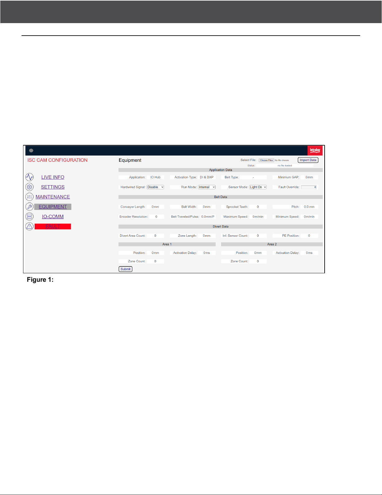
The mode of operation is determined by changing the Run Mode configuration on the EQUIPMENT page of the Virtual
HMI (vHMI). Depending on the required operation mode, the steps may differ slightly.
Run mode selection
ISC CAM IN EXTERNAL MODE
Refer to the electrical schematics for connection details.
Refer to the interlock file for communication, signal exchange, and timing details. Configuration changes may be made
through the vHMI or the parent device connection.
In this mode, the ISC CAM receives all divert commands from a parent device, typically a line PLC, or an inspector. In this
mode, this ISC CAM must be connected to the parent device, either by an ethernet connection, and/or via a 24V discrete
I/O.
To be able to act upon the instructions of the parent device, the ISC CAM is equipped with two options for receiving
commands and providing status updates:
1. Ethernet, allows for sending and receiving complex instructions. Ethernet is usually the preferred option. This mode
allows the parent device to update the settings of the ISC CAM and to receive detailed status and error information.
2. 24 V discrete I/O, allows for sending and receiving messages at high speed. This option is aimed at situations where
communication via ethernet is not fast enough, as is typically seen with inspectors. This option is also aimed at
situations where no ethernet is available. For this mode, two I/Os are dedicated: an input to receive divert commands,
and an output providing a run/error signal. This option is only applicable for the first destination/reject.
NOTE: The ISC CAM puts the lowest priority on vHMI inputs (see Prioritization section). Once communication with the
parent device is set up, some parts of the vHMI may not work for adjustments.

ISC CAM Commissioning Guideline Rev2 November 2022 5
BASIC SETUP
In the situation where both the ethernet and 24 V discrete I/O are used simultaneously, the 24 V discrete I/O takes priority
over the ethernet instructions, using the following logic:
Ethernet 24 V discrete I/O Product divert destination
Destination 0 LOW (0 V) Destination 0 (end off)
Destination 0 HIGH (24 V) Destination 1
Destination 1 LOW (0 V) Destination 1
Destination 1 HIGH (24 V) Destination 1
Destination 2/3/4/5/6* LOW (0 V) Destination 2/3/4/5/6*
Destination 2/3/4/5/6* HIGH (24 V) Destination 1
* Depending on the equipment configuration
ISC CAM IN INTERNAL MODE
Refer to the vHMI documentation on how to use the vHMI to configure the ISC CAM.
Refer to the electrical schematics for connection details.
Refer to the interlock file for communication, signal exchange and timing details, if connected to the parent device.
In internal mode, the ISC CAM performs all actions independently, without the need of interaction with a parent device.
But, to make it possible for the parent device to receive updates, or for it to be updated remotely, we recommend
maintaining an ethernet connection to the parent device.
Once the ISC CAM is configured to function in internal mode, the ISC CAM will fully and autonomously decide how to
divert each product based on preset parameters. This mode can be used to either make the Intralox equipment fully
independent, or to offload work from a parent device.
NOTE: In the absence of external commands, the ISC CAM performs a default action. An external input can update the
internal mode settings, but will not override the default action.
If no parent device is connected, the ISC CAM configuration must be done using the vHMI. If a parent device is connected
via ethernet, the configuration can be done either using the vHMI or via the parent device via the ethernet.
PRIORITIZATION
The ISC CAM prioritizes inputs in the following order:
1. Hardwire signal
2. Parent device
3. vHMI
When connecting a parent device to the ISC CAM, the parent device settings take priority over the vHMI settings even if
the parent settings have no parameters specified. Therefore, make sure the connected parent device has the required set
of parameters. Otherwise, the ISC CAM will not function, regardless of whether the vHMI is in Internal mode or External
mode.
ISC CAM Commissioning Guideline Rev2 November 2022 6
POWER ON
POWER ON
Refer to the electrical schematics for connection details.
Refer to the troubleshooting guide for troubleshooting details.
Once the desired operational mode has been decided and the required electrical connections have been made (see
previous section), the ISC CAM can be powered on.
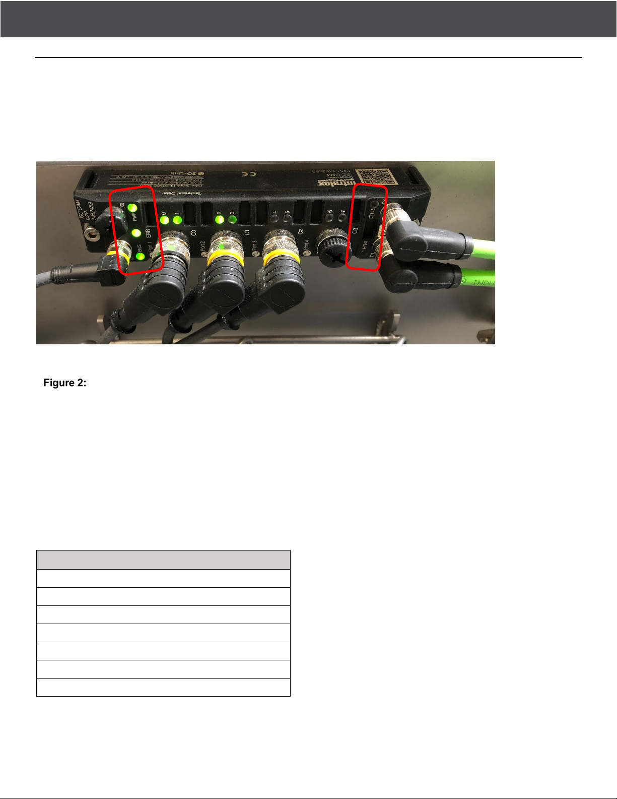
A BUS, ERR, and PWR LED indicators
B ETH1 and ETH2 indicators
Verify power status
The boot process takes about 20 seconds to complete. During this time, the various LEDs on the ISC CAM may flash and
change color a few times. This behavior is normal.
When the boot process is complete, the PWR and ERR LED should be lit green. The BUS LED should flash three (3)
times.
When the ISC CAM is connected to the ethernet, the ETH1 and or ETH2 LED should flash green (100-Mbit connection) or
yellow (10-Mbit connection).
Depending on the equipment configuration, other LEDs may also be lit green.
If any of the following LED conditions is present, an error must be resolved. Refer to the ISC CAM Troubleshooting
Manual.
LED Conditions
PWR LED is lit red
PWR LED is off
BUS LED is lit red (not flashing)
BUS LED slow flashing red or green (1 Hz)
ERR LED is lit red
Port LED IOL 0, 2, 4 or 6 is red or red flashing
Port LED DXP 1, 3, 5 or 7 is red
A
B
ISC CAM Commissioning Guideline Rev2 November 2022 7
NETWORK SETUP
NETWORK SETUP
NOTE: This step is only required if the ISC CAM is connected to a parent device using ethernet.
NOTE: Before continuing, make sure the ISC CAM is correctly, electrically configured and powered as described in the
previous section.
The ISC CAM operates as an integrated device when configured to External mode. The ISC CAM receives external
device communication from the parent device or from another external device on the factory network. In the absence of
external commands, the ISC CAM performs a default action.
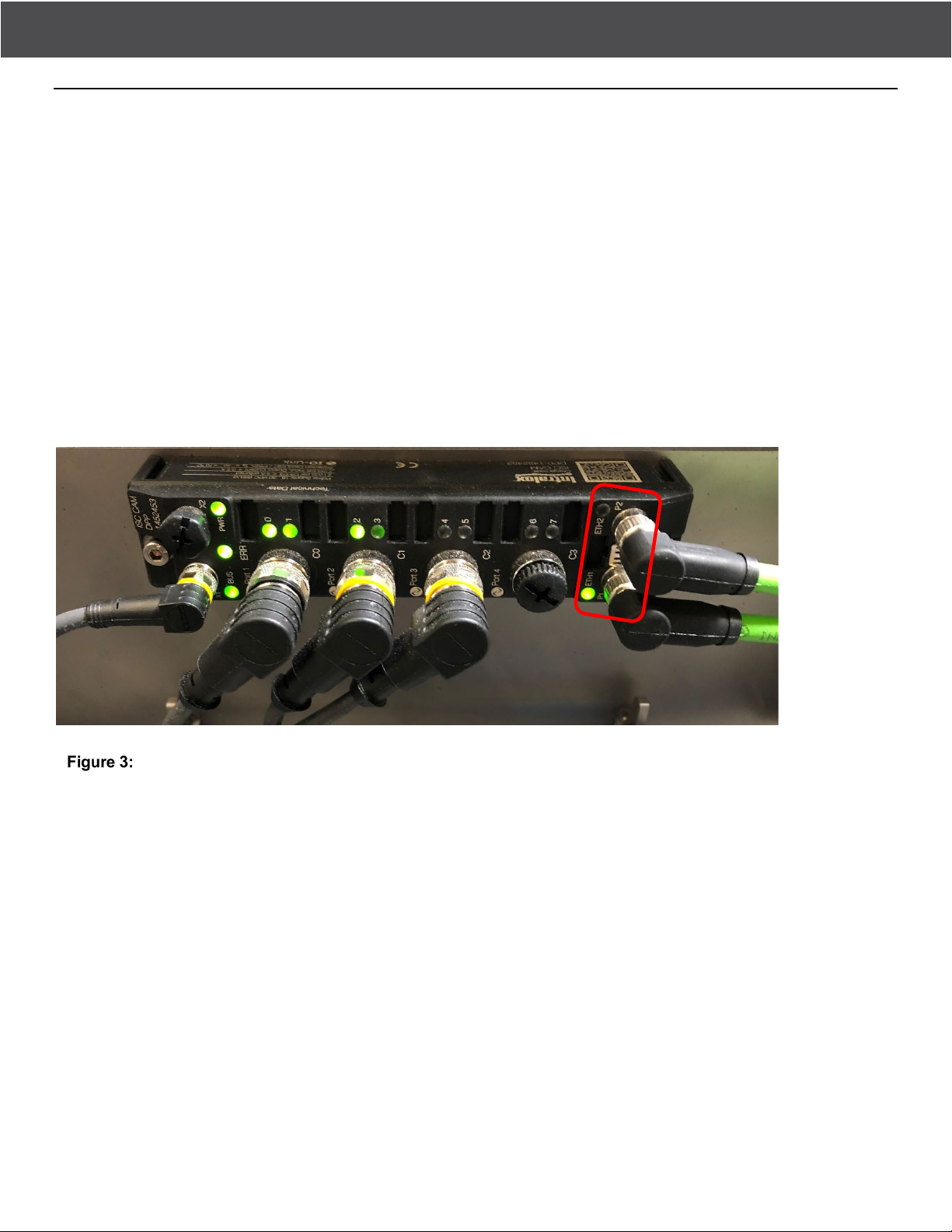
See the ISC CAM Electrical Schematics for ethernet connection points (P1, P2) and the ISC CAM Communication
Interlocks file for data exchange and timing diagram.
Verify ISC CAM ethernet communication per the status LED indicators. The ETH1 and/or ETH2 LEDs should flash green
or yellow during active data exchange.
Intralox standard PLC block / address mapping is available on the Intralox ISC webpage, for easier integration of the ISC
CAM into the network.
A Ethernet: ETH1 and ETH2 LED indicators
Network connections
To allow ethernet communication with the parent device, the IP address and / or Profinet name of the ISC CAM must be
set. This process can be done when downloading the configuration from the parent device, or with the Intralox ISC
Service tool, which is available for download from the Intralox ISC webpage.
A
A

ISC CAM Commissioning Guideline Rev2 November 2022 8
NETWORK SETUP
Intralox ISC service tool
Connect a laptop with the Intralox ISC Service tool installed to the same ethernet network as the ISC CAM. In the Intralox
ISC Service tool, use the Search function to find the ISC CAM on the network. In the list of found devices, highlight the
ISC CAM that requires configuration. If multiple devices are found on the network, and you are unsure the correct ISC
CAM is highlighted, use the wink function to activate a bright white strobe light on the ISC CAM. This action makes it easy
to validate the correct selection. Once the correct ISC CAM is selected in the Intralox ISC Service tool, press Change.
Doing this opens a dialog box allowing you to set both the IP address and the Profinet name.
Depending on the capabilities of the parent device, it may also be possible to configure these settings using the
configuration software of the parent device. Please refer to the manufacturer documentation on how to use this function.

ISC CAM Commissioning Guideline Rev2 November 2022 9
CONNECT TO VIRTUAL HMI
CONNECT TO VIRTUAL HMI
Refer to the electrical schematics for connection details.
Refer to the ISC CAM Quick Startup Guide, on the ISC CAM web page: ISC Setup for vHMI connection details.
NOTE: Before continuing, make sure the ISC CAM is correctly electrically configured and powered as described in the
previous sections.
NOTE: If the ISC CAM is connected via ethernet to a parent device, make sure the ISC CAM network setup is complete
before continuing.
Validate that the ISC CAM configuration file is loaded, as shown in the example, on the vHMI. Validation is done by
comparing the serial number documented on the bottom-right corner of the vHMI screen to the serial number on the ISC
CAM identification plate.
NOTE: If the ISC CAM configuration file is not loaded, contact Intralox Customer Service before proceeding.
Verify configuration file is loaded
When the ISC CAM is electrically connected, powered on, and booted successfully, establish your connection to the
vHMI. Connect the ISC CAM to the computer (using either the ETH1 or ETH2 port).
Connect a computer to the same ethernet network as the ISC CAM. Make sure the network configuration of the computer
matches the network configuration of the ISC CAM. If the network configurations do not match, they will not communicate.
If necessary, consult your system administrator on how to configure your computer network.
NOTE: If the ISC CAM is connected to a parent device, make sure you set up the IP address of your computer with a free
address, to prevent duplication in the network.
To adjust the computer IP address (as required), access ethernet properties through the control panel and select the
“internet protocol v4” configuration. When opening the properties, configure the IP address and subnet mask, as shown in
the Figure. After entering the values, click OK to confirm.

ISC CAM Commissioning Guideline Rev2 November 2022 10
CONNECT TO VIRTUAL HMI
IP address and subnet mask
After your computer IP configuration is completed, open an internet browser. In the address bar of the browser, type the
ISC CAM IP address (either 192.168.1.254 or the IP address set in the previous section) and press ENTER to open the
vHMI (Refer to this video: https://www.youtube.com/watch?v=JL8KZ-bRyqg). Another way to open the vHMI is by double-
clicking the ISC CAM IP address in the main screen of the Intralox ISC Service tool.

ISC CAM Commissioning Guideline Rev2 November 2022 11
VERIFY AND OPTIMIZE
VERIFY AND OPTIMIZE
Confirm the vHMI is connected per the previous section.
VERIFY
ISC CAM CONFIGURATION
A serial number match was verified in the previous section.
PARENT DEVICE COMMUNICATION
Refer to the interlock file on the ISC web page ISC Setup for communication, signal exchange, and timing details.
If ethernet communication is used to communicate with a parent device, use the IO-COMM page to ensure the
communication exchange between the ISC CAM and the parent device is correct. The data words on both the ISC CAM
and the parent device must match.
TEST RUN
Run the ISC CAM without products and verify that all the information, on the LIVE INFO page and the IO-COMM page, is
correct.
On the LIVE INFO page, make sure all relevant diverts are enabled. If connected to a parent device, the parent device
must do this. If not connected to a parent device, the diverts can be disabled/enabled using the vHMI ON/OFF button.
If the ISC CAM operational mode is INTERNAL, use SETTINGS page to set the proper divert count to each divert. If the
ISC CAM operational mode is set EXTERNAL, use the parent device to set a product destination.
Run the ISC CAM with products to validate that the equipment performs the functions required. Refer to the Application
Functional Layout.
Test results may indicate the need for optimization. Alternatively, test results may require troubleshooting under the
following conditions:
Product trajectory issues
Counter deficiencies as viewed on the vHMI (LIVE INFO and MAINTENANCE pages)
ISC CAM generates faults as viewed on the vHMI (FAULT page)
Reference the ISC CAM Troubleshooting document as needed.
OPTIMIZE
Once proper functionality of the Intralox equipment has been established, the ISC CAM can be optimized for the desired
application.
Perform application optimization using the parent device or using the vHMI. Optimization can improve how the ISC CAM
handles various conditions, for example,
Product slugs or trains
Divert positions in Dual-Stacked Angled Roller™ Belt (DARB™) sorting
Peg engagement and product orientation for AIM
See our ISC Setup page on the Intralox website for optimization instructions.

ISC CAM Commissioning Guideline Rev2 November 2022 12
BACKUP
BACKUP
Intralox recommends backing up the file. After the commissioning is completed, create a backup of the application
settings.
In the parent device
Create a backup file using the Save Settings button on the SETTINGS page of the vHMI. Add the backup file to
the technical documentation package of the Intralox equipment.
A Save Settings button
Backup application settings
A

©2022 Intralox, L.L.C. 5012189.4_EN-US 13
CONTACT
CONTACT
Intralox, L.L.C. USA, New Orleans, LA • +1-800-535-8848 • +1-504-733-0463
Intralox, L.L.C. Europe, Amsterdam, The Netherlands • +800-4687-2569 • +31-20-540-36-00
Intralox Shanghai LTD., Shanghai, China • 4008-423-469 • +86-21-5111-8400
For country- and industry-specific contact information, see www.intralox.com.
Table of contents
Popular Accessories manuals by other brands

Di-soric
Di-soric LAT 51 M 500 UG3-B5 quick start guide

EUTECH INSTRUMENTS
EUTECH INSTRUMENTS ALPHA PH DIFFERENTIAL PROBE instruction manual

Climax Technology
Climax Technology MDC-5 user manual

Balluff
Balluff BVS ID-M1280-F1 Series Configuration guide

STEINEL PROFESSIONAL
STEINEL PROFESSIONAL sensIQ eNet Information

Philips
Philips SVC2560W/10 user manual

Liebert
Liebert Liqui-tect 300 installation manual

Siemens
Siemens QGO21 Series Basic documentation

Takex
Takex PS-520E instruction manual

elsner elektronik
elsner elektronik KNX R Installation and adjustment

Sygonix
Sygonix 2267533 operating instructions

Thermo Scientific
Thermo Scientific Emerald Wireless Remote Sensor Supplemental user guide


