8TROUBLESHOOTING
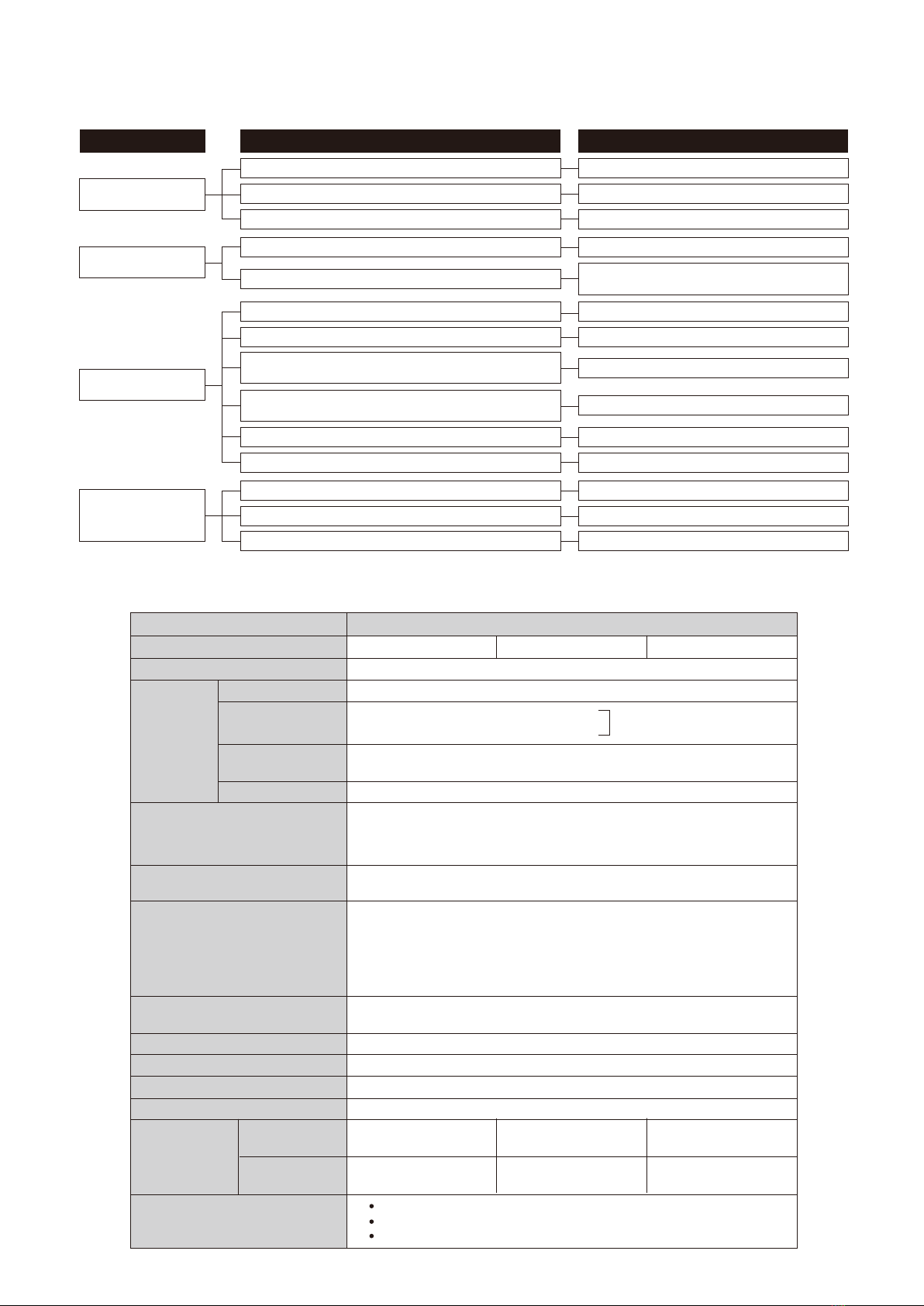
9SPECIFICATION
PRODUCT NAME
MODEL
DETECTION SYSTEM
DETECTION
AREA
POWER SUPPLY
POWER CONSUMPTION
OUTPUT
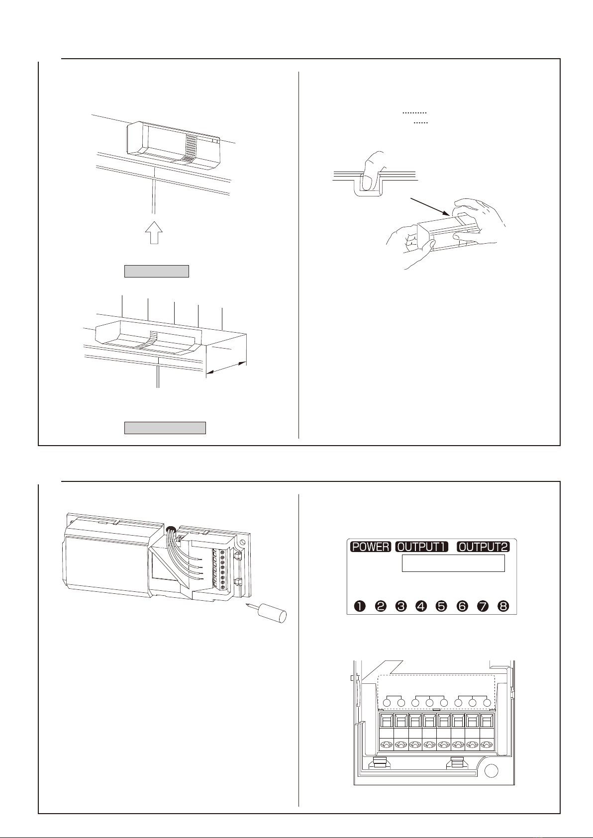
LED
WIRING CONNECTION
AMBIENT TEMP. RANGE
MOUNTING POSITION
WEIGHT
APPEARANCE
ACCESSORIES
REX SENSOR (REQUEST TO EXIT SENSOR)
PS-520E (W)
Passiveinfrared
13'(4m)Max
Single (Door)
Double (Door)
Wall mount : Vertically 35°(8steps)
Overhead mount : Vertically 20°(5steps)
Adjustable
12 to 24VDC (Non polarity)
12 to 24VAC (50Hz / 60Hz)
(UL Listed Class 2)
40mA or less / DC
70mA or less / AC
Dry contact relay 2C
Operation : One shot
Hold time : Adjustable approx. 0.25sec. to 60sec.
Contact capacity : 30VDC 1A or less / 24VAC 0.6A or less
(Class2PowerLimited)
*Selectable relay operation
Green
Operation : synchronous dry contact relay (LED disabled)
Terminals
+14°F to +122°F (−10℃to +50℃) without condensation
Wall, ceiling, on or under frame (indoor)
5.95 oz (170g)
White
White
Tapping screw : 2 pcs.
Resistor (82Ω, 3W) : 1 piece (connect when operated at AC20 to 24V)
Cover locking screw :1 piece
Solve possible problems according to the following table.
If normal operations cannot be restored by this means, contact either the dealer from whom you bought the unit or TAKEX.
Completely inactive
Sometimes inactive
No power supply, broken wire or improper voltage.
Not yet 1 minute after power turned on
Cover shielded by substances (including glass).
Improper area adjustment.
Improper area adjustment.
Cover face is soiled with dust or water drop.
Unstable power voltage.
Something moving in protected area or too rapid temperature
variations.
Intense reflection of sun light or head light shining on the sensor.
Is the sensor reacting to passersby outside ?
Poor contact output connection or broken wire or short circuit.
Contact output is not working.
Is the connected unit operation normal ?
Correct power supply or replace broken wire.
Allow for warming up time (about 1 min.)
Remove the substances.
Readjust the protection area setting.
Readjust the protection area setting.
Stabilize the power voltage.
Remove the cause.
Relocate device.
Relocate device. Shield with a blind.
Readjust the protection area.
Check the wiring or connection.
Check the contact output terminal using a tester.
Check the connected unit.
Clean the cover with soft cloth.
(Do not use chemicals such as thinners or alcohol.)
Activated when no
person has passed
The alarm LED lights,
but connected units
are inactive
Large electrical noise source such as power machine nearby
or its wiring close to that of sensor.
Trouble Check Corrective Action
MOUNTING HEIGHT
PATTERN
ADJUSTMENT
RANGE
SENSITIVITY
COVER
(ABS RESIN)
WINDOW
(PE RESIN)
PS-520E (S)
Selectable
or
or
PS-520E (B)
Silver
White
When operated at AC20 to 24V,
connect attached resistor.
The specications are subject to change without notice.
Bronze
Grey
(
(