InvenSense IXZ-650EVB User manual

Dual-Axis MEMS Gyro Evaluation Board
IXZ-650EVB
InvenSense, Inc., 1197 Borregas, Ave. Sunnyvale, CA 94089, USA 1EB-IXZ-0650-00-02
Tel: +1 (408) 988-7339 Fax: +1 (408) 988-8104 ©2009 InvenSense, Inc. All rights reserved.
Website: http//www.invensense.com
GENERAL DESCRIPTION
The IXZ-650EVB provides a simple means of evaluating the IXZ-
650 X- and Z-axis angular rate gyroscope. The gyro contains all
required conditioning electronics in a single chip measuring 4 x 5
x 1.2mm. The IXZ-650 incorporates X- and Z-axis low-pass filters
and an EEPROM for on-chip factory calibration of the sensor.
Factory trimmed gyro scale factors eliminate the need for external
active components and end-user calibration. A built-in
Proportional-To-Absolute-Temperature (PTAT) sensor provides
temperature compensation information. The product is lead-free
and Green Compliant.
APPLICATIONS
High-Performance Motion Sensing Game Controllers
Pointing Devices
Multimedia Remotes
Computer Mice
PIN DEFINITIONS
FEATURES
Fully-tested board for easy evaluation of dual-axis
(X/Z) gyro
Fully integrated X- and Z-axis gyros on a single chip
2000°/s full scale range
0.5mV/°/s sensitivity
Integrated amplifiers and low-pass filters
Auto Zero function for bias calibration
On-chip temperature sensor
High vibration rejection over a wide frequency range
High cross-axis isolation by proprietary MEMS design
3V single supply operation
Hermetically sealed for temp and humidity resistance
10,000 gshock tolerant
RoHS and Green Compliant
ELECTRICAL SPECIFICATIONS
Pin Signal Purpose
1 OUTX Output of the X-Axis Gyro
2 HPS Auto Zero Input
3 OUTZ Output of the Z-Axis Gyro
4 TEMP Temperature Sensor Output
5 VREF Voltage Reference Output
6 GND Ground
7 GND Ground
8 +VOUT VDD for Gyro
9 GND Ground
10 +VIN Input Supply Pin for LDO
Parameter Specifications Unit
Full-Scale Range ±2000 °/sec
Sensitivity 0.5 mV/°/sec
Cross Axis Sensitivity ± 1 %
Non-linearity < 1 % of FSR
Gyro Supply Voltage 3.0 ±0.3 V
Gyro Supply Current 7 mA
Operating Temperature -20 to +85 °C
On time 50 ms
Shock Tolerance 10,000 g
Component Distributors, Inc.
1-800-777-7334
www.cdiweb.com
sales@cdiweb.com
Downloaded from Arrow.com.

IXZ-650EVB
InvenSense, Inc., 1197 Borregas Ave., Sunnyvale, CA 94089, USA 2EB-IXZ-0650-00-02
Tel: +1 (408) 988-7339 Fax: +1 (408) 988-8104 ©2009 InvenSense, Inc. All rights reserved.
Website: http//www.invensense.com
Purpose
This document provides the specification for the IXZ-650 Dual-Axis Gyroscope Evaluation Board configured per
the table below.
Evaluation Board Configuration
Sensitivity Internal LPF External LPF
0.5 mV/deg/sec 140Hz 2kHz
IC Functional Block Diagram
XAGC 6
ZAGC 15
AZ
24
X4.5OUT
7
14
20
16
IXZ-650
Memory
Trim
Demodulator
Oscillator
Demodulator
Oscillator
Coriolis
Sense
Output Gain
Out
p
ut Gain
Z-Rate
Sensor
X-Rate
Sensor
1
V
DD
Coriolis
Sense
Z4.5OUT
Charge Pump
CPOUT
12
5
Z-OUT
Z4.5IN
X4.5IN
X-OUT
Gain
Low-Pass
Filte
r
+
Gain
Low-Pass
Filte
r
+
Auto Zero
Auto Zero
Optional
External
Filters
Optional
External
Filters
Optional
PTAT
Sensor
23
VREF
Reference
22
Component Distributors, Inc.
1-800-777-7334
www.cdiweb.com
sales@cdiweb.com
Downloaded from Arrow.com.Downloaded from Arrow.com.

IXZ-650EVB
InvenSense, Inc., 1197 Borregas Ave., Sunnyvale, CA 94089, USA 3EB-IXZ-0650-00-02
Tel: +1 (408) 988-7339 Fax: +1 (408) 988-8104 ©2009 InvenSense, Inc. All rights reserved.
Website: http//www.invensense.com
IXZ-650 Evaluation Board Configuration
Schematic
The schematic below specifies the components on the IXZ-650 Evaluation Board.
Bill of Materials
Reference Part
C1 2.2µF/6.3V/Z5R/0402
C2,C6,C8 0.1µF/10V/X5R/0402
C3 4.7µF/6.3V/X5R/0603
C4,C5 JUMPER/0603
C7,C9 0.22µF/6.3V/X5R/0402
C10 0.1µF/25V/X5R/0603
GY1 IXZ-650, 28-Lead QFN (4mm x 5mm x 1.2mm)
JMP1 CON4A/0.050" X 0.1"
J2 Header 1x10, 0.1”, 90D (Mates with AMP # 103976-9)
R1,R5,R8,R16 JUMPER/0402
R3 2.2Ω/5%/0603
R6,R7 750Ω/1%/0402
U1 Voltage Regulator 3.0V ILC7010AIC530X/SC70
C10
0.1uF/25V/0603
C9
0.22uF/0402
C7
0.22uF/0402
R6
750/0402
C8
0.1uF/0402
C6
0.1uF/0402
R1
JUMPER/0402
C2
0.1uF/0402
5V
3V
R7
750/0402
AZ (Labeled as “HPS”)
GY1
IXZ-650, 28-Lead QFN (4mm x 5mm x 1.2mm)
GND
26
GND
27
GND
28
VDD
9
GND 2
X- O U T
1
XAGC 6
CPOUT 12
ZAGC 15
Z-OUT
20
VDD
19
AZ 24
VREF 22
PTATS 23
C4
JUMPER/0603
U1
ILC7010AIC530X/SC70
Vin 5
Vout
4
En 1
NC
2
GND 3C3
4.7uF/0603
Mates with AMP # 103976-9
R3
2.2 ohm/0603
OUTZ
J2
CON10
1
2
3
4
5
6
7
8
9
10
+VOU T
+VIN
CUSTOMER I/O
PTAT
OUTX
R16
JUMPER/0402
R5
JUMPER/0402
C1
2.2uF/0402
JMP1
1
3
2
4
VREF
C5
JUMPER/0603
R8
JUMPER/0402
Component Distributors, Inc.
1-800-777-7334
www.cdiweb.com
sales@cdiweb.com
Downloaded from Arrow.com.Downloaded from Arrow.com.Downloaded from Arrow.com.

IXZ-650EVB
InvenSense, Inc., 1197 Borregas Ave., Sunnyvale, CA 94089, USA 4EB-IXZ-0650-00-02
Tel: +1 (408) 988-7339 Fax: +1 (408) 988-8104 ©2009 InvenSense, Inc. All rights reserved.
Website: http//www.invensense.com
Special Instructions
Electrostatic Discharge Sensitivity
The IXZ-650 gyro can be permanently damaged by an electrostatic discharge. ESD precautions for
handling and storage are recommended.
Jumper Connector
The IXZ-650 evaluation board is equipped with a jumper connector to control the voltage supplied to the
gyro. When the jumper is located in the “up” or standard position as shown in the picture above, the 5
Volts being supplied to the gyro is regulated to 3 Volts using an on-board regulator. When the jumper is
located in the “down” position, the on-board regulator is bypassed and the gyro is being directly supplied
with the voltage on Pins 9 and 19 of the IC.
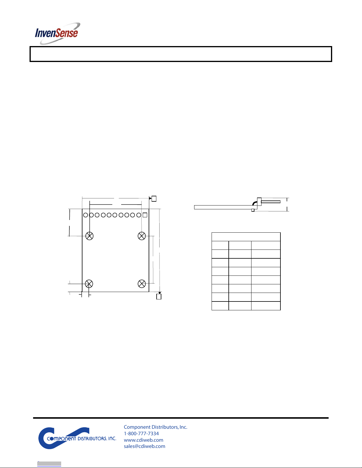
Dimensional Drawing
This information furnished by InvenSense is believed to be accurate and reliable. However, no responsibility is assumed by InvenSense for its use, or for any infringements of patents or
other rights of third parties that may result from its use. Specifications are subject to change without notice. InvenSense reserves the right to make changes to this product, including its
circuits and software, in order to improve its design and/or performance, without prior notice. InvenSense makes no warranties, neither expressed nor implied, regarding the information
and specifications contained in this document. InvenSense assumes no responsibility for any claims or damages arising from information contained in this document, or from the use of
products and services detailed therein. This includes, but is not limited to, claims or damages based on the infringement of patents, copyrights, mask work and/or other intellectual property
rights.
Certain intellectual property owned by InvenSense and described in this document is patent protected. No license is granted by implication or otherwise under any patent or patent rights of
InvenSense. This publication supersedes and replaces all information previously supplied. Trademarks that are registered trademarks are the property of their respective companies.
InvenSense sensors should not be used or sold in the development, storage, production or utilization of any conventional or mass-destructive weapons or any other weapons or life
threatening applications, as well as in any other life critical applications such as medical equipment, transportation, aerospace and nuclear instruments, undersea equipment, power plant
equipment, disaster prevention and crime prevention equipment.
©2009 InvenSense, Inc. All rights reserved.
A
B
D
E
E2
D2
L
L1
L2
Dimensions (mm)
A 5.0 ±1.0
D 25.7 ±0.1
E 31.8 ±0.1
L 3.1 ±0.1
L1 3.1 ±0.1
L2 10.2 ±0.1
D2 19.5 ±0.1
E2 18.5 ±0.1
A
SIDE
TOP
Component Distributors, Inc.
1-800-777-7334
www.cdiweb.com
sales@cdiweb.com
Downloaded from Arrow.com.Downloaded from Arrow.com.Downloaded from Arrow.com.Downloaded from Arrow.com.
Other InvenSense Motherboard manuals