Inventronics CNV-DMXR User manual

1 / 12
Specifications are subject to changes without notice.
CNV-DMXR Tool User Manual Version 3.0
CNV-DMXR Tool User Manual

2 / 12
Specifications are subject to changes without notice.
CNV-DMXR Tool User Manual Version 3.0
Content
CNV-DMXR Tool User Manual ................................................................................................................ 1
Purpose ......................................................................................................................................................... 3
Required Materials ....................................................................................................................................... 3
Wiring Diagram ............................................................................................................................................. 3
Instructions ................................................................................................................................................... 3
Software Installation..................................................................................................................................... 4
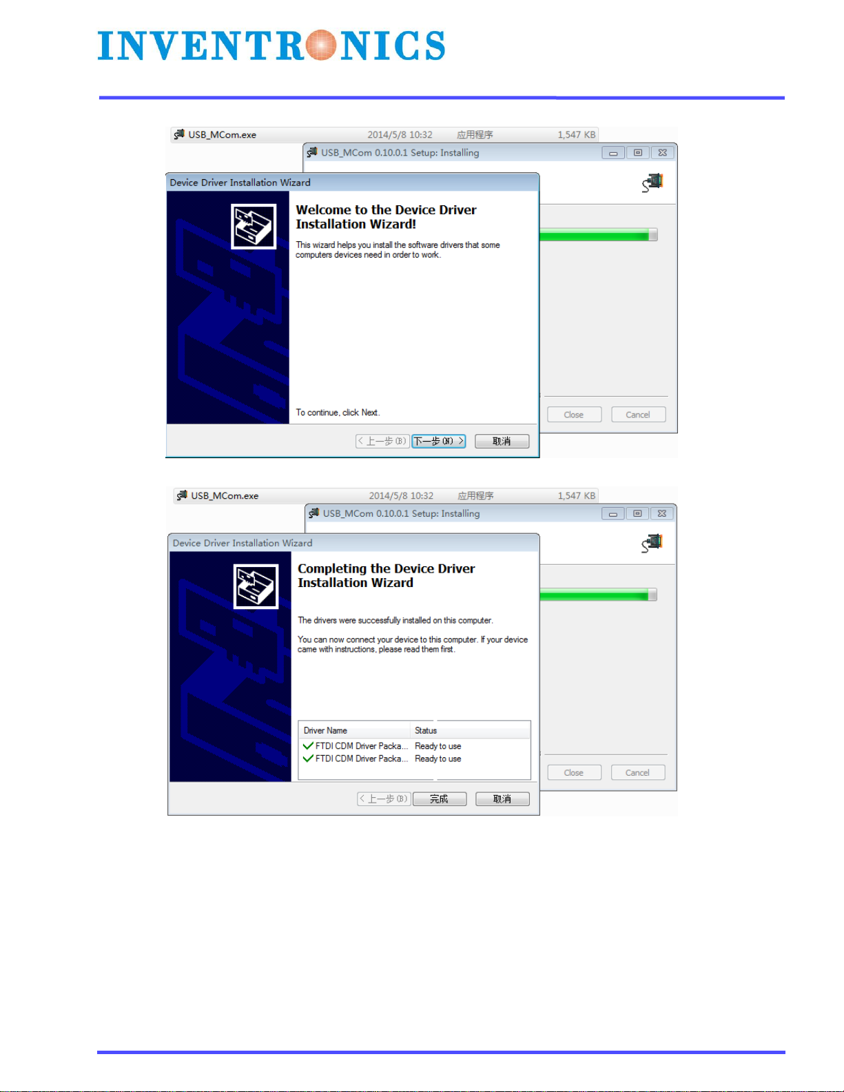
Install the USB driver and serial port driver library .................................................................................. 4
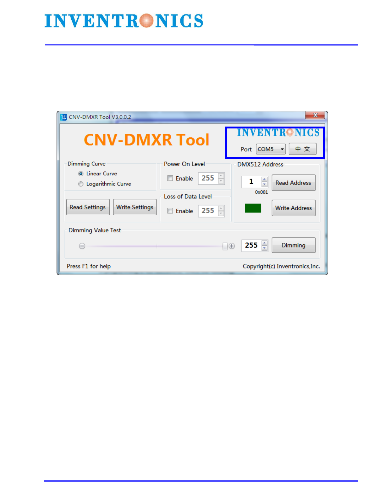
User Interface ............................................................................................................................................... 6
Port Selection............................................................................................................................................ 6
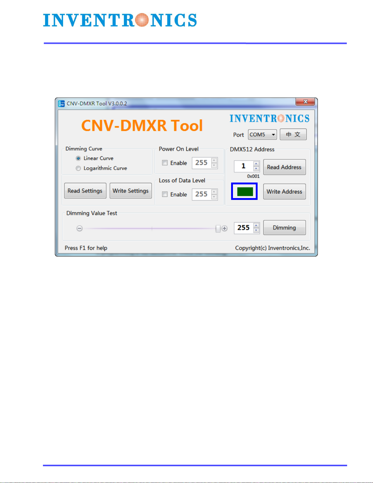
Indicator Box............................................................................................................................................. 7
DMX512 Address....................................................................................................................................... 8
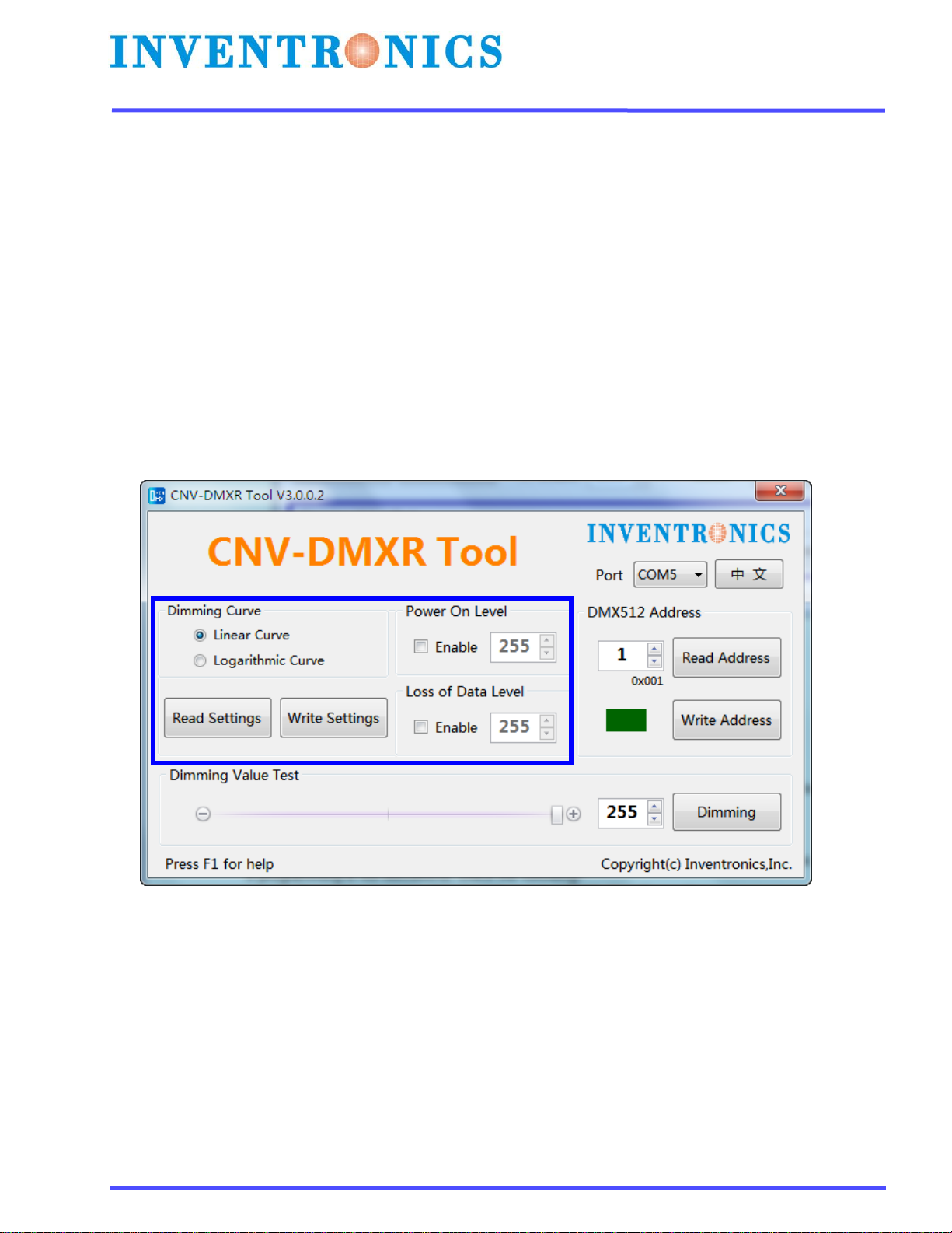
Parameters Setting ................................................................................................................................... 9
Dimming Value Test ................................................................................................................................10
Troubleshooting..........................................................................................................................................11
No Port Shown ........................................................................................................................................ 11
Programming Error ................................................................................................................................. 11
Shortcut operation...................................................................................................................................... 12

3 / 12
Specifications are subject to changes without notice.
CNV-DMXR Tool User Manual Version 3.0
Purpose
To allow users to set the DMX address, and change the dimming curve of the CNV-DMXR
without the use of a DMX RDM master.
Required Materials
UTEK UT890
CNV-DMXR
PC (win XP, win 7 Microsoft .NET Framework 4.0)with CNV-DMXR Tool installed
Wiring Diagram
A wiring diagram for connections required to program the CNV-DMXR can be seen below in Figure 1.
12 VDC, 200mA Max
UTEK UT890
Vcc
Gnd
Rxd-
Rxd+
T/R-
T/R+
Inventronics
CNV-DMXR
Purple: Dim+
Gray: Dim -
Black: 12v
Purple: DMX+
Gray: DMX-
Black: Shield
USB to PC
Figure 1: Wiring Diagram
Instructions
1. Connect CNV-DMXR to the UTEK UT890
a. CNV-DMXR Data+ to UT890 T/R+
b. CNV-DMXR Data- to UT890 T/R-
*Note: Only one set of the CNV-DMXR DMX leads needs to be connected to the UT890. Either
set can be used.
2. Connect CNV-DMXR to 12 VDC
a. Dim- to 12VDC- of DC source or Inventronics Controls Ready driver
b. Vaux to 12VDC+ of DC source or Inventronics Controls Ready driver
Note: CNV-DMXR will not consume more than 200mA
3. Open DMXR Tool

4 / 12
Specifications are subject to changes without notice.
CNV-DMXR Tool User Manual Version 3.0
Software Installation
Install the USB driver and serial port driver library
1. extract the file USB_MCom.rar
2. run USB_MCom.exe
3. Enter the installation interface, click on the next step, and then click Finish

5 / 12
Specifications are subject to changes without notice.
CNV-DMXR Tool User Manual Version 3.0

6 / 12
Specifications are subject to changes without notice.
CNV-DMXR Tool User Manual Version 3.0
User Interface
Port Selection
The CNV-DMXR Tool will automatically detect if a UT890 is connected to the PC via USB on program
startup. The port being used will be displayed in the upper right corner. If no port is shown, see the
Troubleshooting section below. The port selection portion can be seen in Figure 2 below.
Figure 2: Port Selection

7 / 12
Specifications are subject to changes without notice.
CNV-DMXR Tool User Manual Version 3.0
Indicator Box
The indicator will either show as “Red” or “Green.” “Red” means that a read or write was not successful,
and “Green” indicates a successful read or write. When the software is opened, the indicator box will
show as “Green.”
The indicator box can be seen highlighted in Figure 3.
Figure 3: Indicator Box

8 / 12
Specifications are subject to changes without notice.
CNV-DMXR Tool User Manual Version 3.0
DMX512 Address
To view the current programmed address of the CNV-DMXR, press the “Read Address” button. If the read
address function is successful, the indicator will turn green, and the address will change. The default
address of the CNV-DMXR is “2.”
To write a new address to the CNV-DMXR, type in the desired address in the text box, and click “Write
Address.” DMX address must be in the range of 1 to 512.
The DMX512 Address programming box can be seen below in Figure 4.
Figure 4: DMX512 Address programming section

9 / 12
Specifications are subject to changes without notice.
CNV-DMXR Tool User Manual Version 3.0
Parameters Setting
(1)、The CNV-DMXR allows for 2 different dimming curves to be selected. These dimming curves are
“Linear” and “Logarithmic.” Only one dimming curve can be selected at a time. The default dimming curve
is “Linear.”
(2)、After an external power cycle, the CNV-DMXR shall activate the power on level (range of validity :
0 - 255 ) , if the Power On Level function is enabled. If it is not set, the default level is 0.
(3)、When encountering a loss of data condition, the CNV-DMXR shall remain in an operating
condition for at least 60 seconds, awaiting resumption of the DMX512 signal, after that, if devices are still
in the loss signal condition, then activate the loss of data level (range of validity : 0 - 255 ) , if the Loss of
Data Level function is enabled. If it is not set, the CNV-DMXR remain in the previous level.
To view the current parameters settings, click on “Read Settings.” To change the parameters settings,
select the desired parameters, and then click “Write Settings.” A successful read or write to the
parameters settings will result in a green light. If an issue is present, the indicator box will show red. The
dimming curve section can be seen in Figure 5 below.
Figure 5: Dimming Curve section

10 / 12
Specifications are subject to changes without notice.
CNV-DMXR Tool User Manual Version 3.0
Dimming Value Test
The dimming value test allows for quick testing of DMX networks. To use this function, put the desired
test address in the address box, and then select the desired dimming value. To send the dimming value,
click on the “Dimming” button. The “Dimming Value Test” function is meant for troubleshooting and
development. Inventronics also recommends testing with a standard DMX controller, as the CNV-DMXR
tool only broadcast one command at a time, while standard DMX controllers are constantly broadcasting
data. The Dimming Value Test box can be seen in Figure 6 below.
Figure 6: Dimming Value Test

11 / 12
Specifications are subject to changes without notice.
CNV-DMXR Tool User Manual Version 3.0
Troubleshooting
No Port Shown
If no port is shown, the UT890 has not been detected.
Follow the steps listed below:
Exit the CNV-DMXR Software
Check the USB connection from the PC to the UT890
If no port is still detected after the software is restarted and connections are checked, ensure that
the UT890 device driver has installed correctly.
Programming Error
If the programming is successful, the indicator box will change to green. If there is an issue, it will turn red.
If programming is not successful, check the following
Connection between CNV-DMXR and the UT890 (See Figure 1)
Ensure that the CNV-DMXR is powered (12VDC, 200mA max)
Check that the port field is populated

12 / 12
Specifications are subject to changes without notice.
CNV-DMXR Tool User Manual Version 3.0
Shortcut operation
To simplify the operation, CNV-DMXR tool provides several shortcuts. Press the “Alt” key to give a prompt.
•Read Address is R;
•Write Address is W;
•Dimming is D;
•Press F1 can read manual
Table of contents