Inventus Power PROTRXion M-24V80-TRX User manual

inventuspower.com
+1 877.423.4242
Inventus Power, Inc.
1200 Internationale Parkway
Woodridge, IL 60517
Designed & Manufactured by
PROTRXion™
Battery User Manual
M-24V80-TRX
M-24V90-TRX
M-36V80-TRX
M-48V60-TRX

2
PROTRXion™ Battery User Manual
Applicable Models
Document Information
Environmental Regulations
The battery pack is compliant with the following environmental regulations:
• EU Directive 2002/95/EC for Restriction of Hazardous Substances (RoHS)
• EU Directive 2006/66/EC on batteries and accumulators and waste batteries and accumulators
• EU Directive 1907/2006 on the Registration Evaluation Authorization and Restriction of
Chemicals (REACH)
• Management Methods for Controlling Pollution Caused by Electronic Information Products
Regulation (China RoHS)
Model Part No. (CANopen)
M-24V80-TRX (w/ heater) 58571-002
M-24V90-TRX (w/ heater) 57481-002
M-36V80-TRX (w/ heater) 58946-201
M-48V60-TRX (w/ heater) 58560-202
M-48V60-TRX (w/ heater)
European Market Only 59092-201
M-24V80-TRX (w/out heater) 58571-005
M-24V90-TRX (w/out heater) 57481-003
M-48V60-TRX (w/out heater) 58560-601
Release Date Revision Scope of Change
2022-07-21 V2.0 Version 2 Release

3
PROTRXion™ Battery User Manual
DOCUMENT NOTICE: The information contained in this manual is the property of Inventus Power
and is subject to change without notice. Inventus Power reserves the right to make changes in
the design of its products or components as progress in engineering and manufacturing may
warrant. It is the customer’s responsibility to satisfy itself as to whether the information contained
herein is adequate and sucient for a user’s particular use. It is the further responsibility of
each user to ensure that all applications of Inventus Power products are appropriate and safe
based on conditions anticipated or encountered during use. This document does not create
any additional obligation for Inventus Power and does not constitute additional warranties and
representations.
Technical Support: For any issues, please email tech_support@inventuspower.com
Inventus Power® and PROTRXion™ are trademarks of Inventus Power.
Copyright© 2021 Inventus Power All rights reserved.
Please read all contents of this User’s Manual prior to the installation
of Inventus Power PROTRXion™ Batteries.
CANOpen Controller Area Network Bus communication CCCV Constant Current Constant Voltage
J1939 Higher-layer CANbus protocol for data logging OTC Over Temperature Charging
OCV Over Charge Voltage OTD Over Temperature Discharging
AFE Analog Front End TCO Thermal Cuto
BMS Battery Management System SOT Safety Over Temperature
CC Constant Current SOC State of Charge
CID Current Interrupt Device OCV Open Circuit Voltage
COV Cell Over Voltage RT Room Temperature
DOD Depth of Discharge Ah Ampere Hour
OCC Over Current Charge CUV Charge Under Voltage
LED Light Emitting Diode
Abbreviations

4
Contents
Abbreviations ................................................................................................................................ 3
Safety Information ....................................................................................................................... 5
Personal Protective Equipment / Installation Tools ........................................................... 6
Unboxing the Battery .................................................................................................................. 6
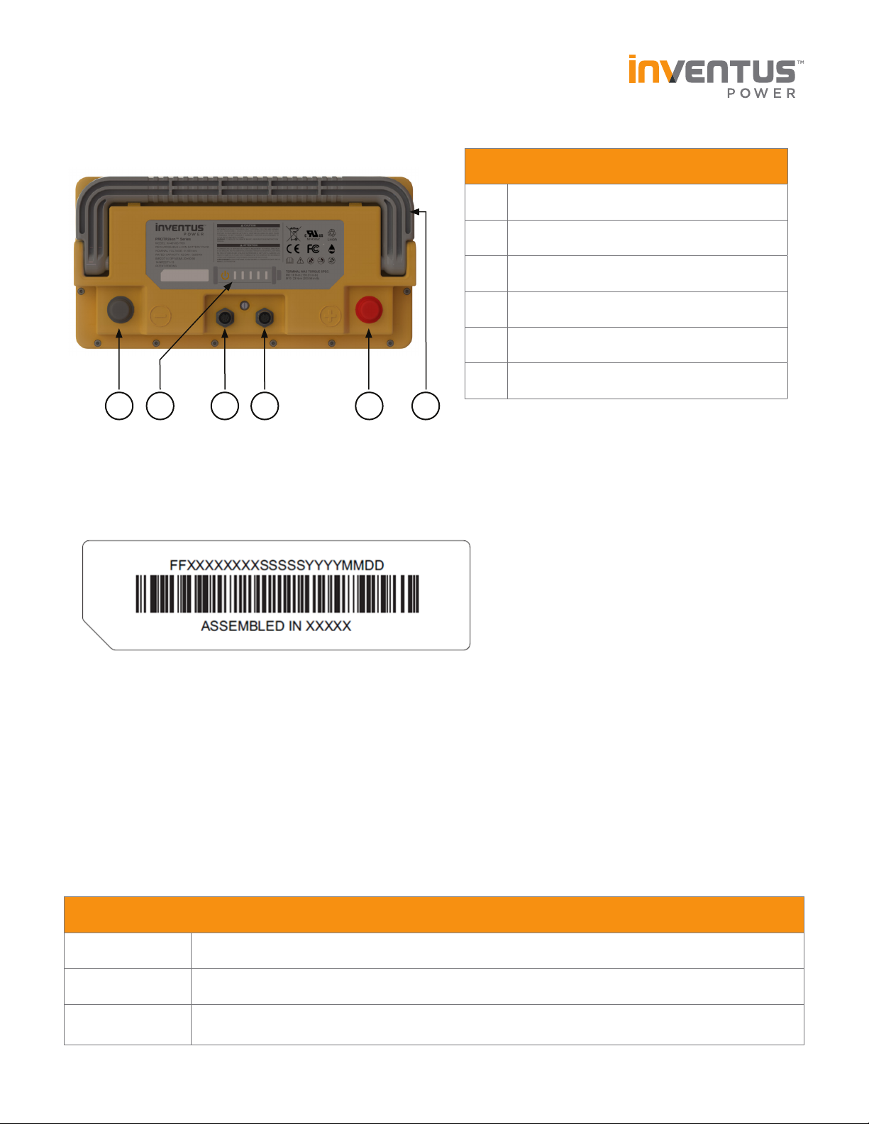
Mechanical Features .................................................................................................................... 7
Battery Serial Number Format ................................................................................................. 7
Product Dimensions .................................................................................................................... 7
Wake-Up & Ship Mode ................................................................................................................ 8
Selecting Power Cables .............................................................................................................. 9
Communication Cables ............................................................................................................... 9
Selecting a Battery Charger .................................................................................................... 10
Connecting the Battery ............................................................................................................. 11
Battery Terminal Torque Rating .............................................................................................. 11
Module Configuration ................................................................................................................ 12
Communications .......................................................................................................................... 13
Pin Definition ............................................................................................................................... 14
Battery Modes............................................................................................................................... 15
Battery State of Charge Indicator .......................................................................................... 16
Heater Operation ......................................................................................................................... 16
Disconnecting the Battery ........................................................................................................ 17
Battery Specifications ................................................................................................................ 17
Battery Performance Data ........................................................................................................ 18
Maintenance, Storage, and Disposal ..................................................................................... 20
Transporting Lithium-ion Batteries ........................................................................................ 21
Emergency and First Aid Procedures ................................................................................... 23
Troubleshooting ......................................................................................................................... 24
Serial Number Record ............................................................................................................... 25
Warranty Violations ................................................................................................................... 26
Recycling ...................................................................................................................................... 27
Technical Support ...................................................................................................................... 27

5
DO DO NOT
Symbol Definition
Important safety information will follow.
DO NOT dispose of battery in fire.
RECYCLE! Battery may require recycling in accordance with local laws. Regardless,
recycling is encouraged. Contact local regulatory authorities for more information.
DO NOT include battery with lead acid battery recycling.
DO NOT dispose of battery in the trash.
Shock Hazard - Labels may be located on or inside the equipment to alert people that
dangerous voltage may be present.
Burn Hazard - Labels may be located on or inside the equipment to alert people that
surface temperature may be dangerous.
• Always wear proper personal protective
equipment
• All installation should be performed by a
qualified service technician
• Use only insulative tools required for
assembly
• Dispose of the battery properly in
accordance with local, state, and federal
regulations
• Extinguish any flames with a carbon
dioxide, dry- powder fire extinguisher, and
cover with copious amounts of water
• Do not use with other types of batteries
connected with the PROTRXion™ products
• Do not short circuit the battery terminals
• Do not operate or store the battery beyond
the operating limits
• Do not over-charge or over-discharge the
battery
• Do not crush, puncture, or drop the battery
• Do not immerse battery in water
• Do not burn or expose battery to fire
• Do not charge battery near flammable
materials, liquids, and surfaces
• Do not alter, disassemble, modify, or open
battery
• Do not wear jewelry (i.e. rings, watches,
bracelets, necklaces) when handling or
working near the battery
• Do not lift battery by the terminal cables
• Do not operate if battery has been damaged
in any way during shipping
Safety Information

6
Personal Protective Equipment / Installation Tools
Before installation or maintenance of your batteries, the following equipment
is required:
• Rubber gloves
• Safety goggles or other eye protection
• Insulated Torque Wrench / Philips Screwdriver
• Voltmeter
Unboxing the Battery
Before You Start
Please read all the safety and warranty information provided in this document prior to installing
and/or operating the battery.
IMPORTANT: Remove all jewelry or other metallic objects from your hands and
body during the installation and removal of the battery packs and peripherals.
What’s in the Box?
• Inventus Power PROTRXion™ battery
• UNDOT 38.2 / IATA approved packaging
• QR Code Slip to access manuals, datasheets, and more supporting documents
• Signal connector dust covers (pre-installed on battery)
• Terminal bolts (pre-installed on battery)
• Protective battery terminal covers
Note: All power and signal cables must be purchased seperately.
Unpacking
• If possible, do not discard the packaging. This packaging is designed for the safe transporta-
tion of lithium-ion batteries compliant with gloabl shipping regulations and can be reused if
the battery must be transported to a new location.
Visual Inspection
• Please inspect each battery carefully. Report any damage from shipping to Inventus Power
immediately.

7
Specification M-24V80-TRX M-24V90-TRX M-36V80-TRX M-48V60-TRX
Length 346 ± 2.0mm
Width 178 ± 2.0mm
Height 258 ± 2.0mm
# Description
1Negative Terminal
2Signal Connector #1
3Signal Connector #2
4Positive Terminal
5Battery State of Charge Indicator
6Retractable Pull Handle
Mechanical Features
M-24V80-TRX / M-24V90-TRX / M-36V80-TRX / M-48V60-TRX
Battery Serial Number Format
FF Factory Location (TJ: Tijuana, Mexico; QX: QingXi, China)
XXXXXXXX Work Order Number (8 digits)
SSSSS Battery Serial Number (00001-65535)
YYYYMMDD Mfg Date (Year, Month, and Day)
Product Dimensions
5 61 2 4
3

8
Wake-Up & Ship Mode
Press the SOC button
for 5 seconds
TO WAKE UP THE BATTERY
TO PLACE IN SHIP MODE
We recommend to place the battery
in Ship Mode when it is not used to
prevent self-consumption current
drain and extend storage life.
Press the SOC button
for 20 seconds
Pin 1
Pin 5
VINTLK
Pin 4
VGND
Pin 3
VWAKE
Battery can also receive a wake up signal
from the signal connector by shorting
pin 4 (VGND) to pin 5 (VINTLK) to wake
up battery from Ship Mode.
Wake-Up
Connect pins 4 & 5
to exit Ship Mode
12 3 4 5 6 7 8

9
Selecting Power Cables
Choose the appropriate power cable size based on the system load requirements. Cables are
rated at ambient temperature of 30°C (86°F) per the table below. When connected in parallel
configuration, it is preferable for all cables to be the same length size.
Communication Cables
If your application requires communication, please connect a CAN cable to the battery signal
connector and respective system or chargers.
Copper Wire Gauge (AWG) Metric Wire Cross-Section (mm2) Ampacity (A)
14 2.081 20
12 3.309 25
10 5.261 30
8 8.366 50
6 13.302 65
4 21.151 85
3 26.671 100
2 33.632 115
1 42.409 130
0 (1/0) 53.460 150
00 (2/0) 67.400 175
Item Mfg Part No. Cable Length Where to Purchase
Pack to Host T4161120008-001 0.5 meter (1.64') Digikey
Pack to Pack M12A08MR-12AMR-SBA05 0.5 meter (1.64') Digikey

10
Selecting a Battery Charger
Many types of lead acid chargers are compatible with our PROTRXion™ batteries and safely
charge in temperature ranges as shown in the table below. The charger maximum voltage out-
put should match the maximum charge voltage of the battery system and should not exceed
constant voltage as shown in the table below. It is recommended to charge the battery prior to
installation. Consult with Inventus Power for recommendation on selecting a battery charger.
After the charger has been selected, first connect the (-) terminal to the battery, then the (+)
terminal. Once the terminals have been connected, connect the CAN communication to the
battery to optimize the charger performance (preferred chargers recommended by Inventus
Power).
Charge Voltage / Current
Float Charge Voltage
Charger Current
Max charge current rate will vary depending on ambient temperature and battery state of charge.
Charging above the recommended current rate may impact the battery cycle life. For more de-
tailed information on charging profile, please discuss with Inventus Techincal Support.
When choosing an intelligent charger, please discuss with Inventus Technical Support on suitable
o-the-shelf charger solutions.
Model M-24V80-TRX M-24V90-TRX M-36V80-TRX M-48V60-TRX
Charge Voltage 28.0 VDC 28.0 VDC 41.0 VDC 58.1 VDC
Charge Current 40A (0.5C) 45A (0.5C) 26.4A (0.33C) 18A (0.3C)
Max Charge Current 80A (1.0C) 90A (1.0C) 40A (0.5C) 20A (0.33C)
Charge Temperature
(without heater)
0°C to 55°C
(32°F to 131°F)
0°C to 45°C
(32°F to 113°F)
Charge Temperature
(with heater)
-35°C to 55°C
(-31°F to 131°F)
-35°C to 45°C
(-31°F to 113°F)
Model M-24V80-TRX M-24V90-TRX M-36V80-TRX M-48V60-TRX
Float Voltage 27.6 VDC 27.6 VDC 41.0 VDC N/A

11
Connecting the Battery
1. Remove power to the vehicle/device prior to installation of the PROTRXion™ battery.
2. Remove all other batteries from the system prior to replacing them with PROTRXion™
batteries.
3. Remove the protective battery terminal covers from the terminals. Retain these covers in
the event that you need to remove or move the battery at some future time.
4. Attach the negative cable from the device to the negative terminal on the battery.
5. Attach the positive cable from the device to the positive terminal on the battery.
6. Attach M12 communication cables between batteries if more than one battery and from
battery to host system if the host system requires CANbus communication. Connect com-
munication cables to the TE M12 connector on the battery with 0.60 Nm [6.1 kgfcm] or less
torque in order to maintain good connection and avoid damaging the battery. DO NOT
rotate the mating connector or loosen the nut on the battery M12 connectors to avoid dam-
aging the battery.
7. If the battery charger is integrated with the device drawing power from the PROTRXion™
battery, then please follow manufacturers recommended sequence for each battery connection.
8. Please contact Inventus Technical Support if the system requires more than 10 batteries.
Battery Terminal Torque Rating
CAUTION: When using bolts to engage the battery’s threaded holes, use the appropriate
number of flat and lock washers to allow for as much thread engagement as possible with-
out bottoming out the bolt. Over-tightening battery terminal bolts could result in damage to
battery terminals. Under-tightening battery terminals could result in excessive heating of the
terminals.
Model Terminal Type Wrench
Size
Torque
(Nm)
M-24V80-TRX
M-24V90-TRX
M-36V80-TRX
M-48V60-TRX
ISO M8 x 1.25 x 20mm Bolt (Negative Terminal) 13mm 17 ± 1
ISO M10 x 1.5 x 20mm Bolt (Positive Terminal) 17mm 22 ± 1
CAUTION: Do not connect batteries with reversed battery leads i.e. with the
pack positive terminal connected to the source or system negative terminal or
the pack negative terminal connected to the source or system positive terminal.
Failure to follow proper connection sequence can damage the battery
and void the warranty.

12
Module Configuration
Warning: Do not connect batteries in series. Connecting in series exceeds the voltage limit of
the integrated safety protection circuitry and can damage the battery and void the warranty.
Parallel connections
Two or more batteries can be connected together in parallel to increase the capacity of the
battery system. The negative terminal of the first battery is connected via jumper cable to the
negative terminal of the second battery. Use another set of jumper cables with the same wire
gauge to connect the positive terminals of both batteries together. Connect a signal cable from
one signal port to another. This connection process can be repeated to up to the max scalability
or until the desired capacity is reached. Finally, use another set of power cables with the same
wire gauge to connect the positive terminal from the first battery and the negative terminal from
the last battery in the parallel chain to the host system. This will ensure proper balancing of the
system. See parallel connection diagram below.
Note: CAN lines in the battery pack DO NOT have internal termination resistance. It is
recommended to properly terminate the system and battery CAN Bus lines following the CAN
Bus termination standards. For any technical questions about properly adding termination
resistance, please contact technical support at tech_support@inventuspower.com.
Single Install Parallel Connection
Pack (-)
Signal Cable
(System)
Pack (+)
Signal Cable
(System)
Pack (+)
Pack (-)
Signal Cable
(Pack to Pack)

13
Communications
• Each PROTRXion battery uses two female Tyco Electronics M12 connectors to support
signal communication with the host system.
• Communications are disabled until the battery is awake.
• Voltage, current, temperature, capacity, cycle count, state of charge, and fault codes can
be read from the battery using CANopen or J1939 communication. Communication protocol
of the battery is dependent on part number not model name.
• A signal interface is used as the communication interface between the battery and a connected
device.
If in doubt, please consult with
Inventus Power Technical Support
(tech_support@inventuspower.com)
on further instructions on the signal
cable connections to the host system.
TE Connector P/N: T4131012081-000

14
Pin # Symbol Description
1VCANH CAN High for communication to the vehicle/machine
2VCANL CAN Low for communication to the vehicle/machine
3VWAKE Wake up input pin – active low to enable discharging
4VGND Pack signal ground used to pull Wake up and Interlock low
5VINTLK Interlock input pin – active low to enable charging
6VCANH_BATT CAN High for module to module communications
7VCANL_BATT CAN Low for module to module communications
8VSUPPLY Unregulated 24V/36V output – 2A continuous max.
Pin # Symbol Description
1VCANH CAN High for communication to the vehicle/machine
2VCANL CAN Low for communication to the vehicle/machine
3VWAKE Wake up input pin – active low to enable discharging
4VGND Pack signal ground used to pull Wake up and Interlock low
5VINTLK Interlock input pin – active low to enable charging
6VSUPPLY Aux Power Supply (15V, <15mA current limit)
7VCANL_BATT CAN Low for module to module communications
8VCANH_BATT CAN High for module to module communications
Pin Definition
Pin Definition (M-24V80-TRX / M-24V90-TRX / M-36V80-TRX)
Note: VSUPPLY 24V/36V is always on except for during Ship mode and,
Over/Under Temperature and Cell Undervoltage Conditions.
Pin Definition (M-48V60-TRX)

15
Battery Modes
*Discharge also allowed in this mode unless discharge fault condition is detected in which case discharge MOSFETs are
opened.
**Charge also allowed in this mode unless charge fault condition is detected in which case charge MOSFETs are opened.
Sleep Mode
Disconnect pins 3, 4 & 5
to put into Sleep Mode
Charge Mode
Connect pins 4 & 5
to enter Charge Mode
Discharge Mode
Connect pins 3 & 4
to enter Discharge Mode
12 3 4 5 6 7 8 12 34 5 6 7 8 12 34 5 6 7 8
Mode Name VWAKE VINTLK Action Mode Description
Sleep O
(High or Hi-z)
O
(High or Hi-z)
Disconnect pins 3, 4, and
5 to enter Sleep Mode
Low power mode,
MOSFETs open
Charge O
(High or Hi-z)
On
(Low)
Connect pins 4 and 5 to
enable charging
Charge allowed*,
MOSFETs closed
Charge On
(Low)
On
(Low)
Connect pin 4 to pins 5
and 3 to enable charging
Charge allowed*,
MOSFETs closed
Discharge On
(Low)
O
(High or Hi-z)
Connect pins 3 and 4 to
allow discharging
Discharge allowed**,
MOSFETs closed
Ship O
(High or Hi-z) N/A Press the SOC button
and hold for 20 sec
Low power mode,
MOSFETs open
Shutdown N /A N /A Apply charge voltage to
exit Shutdown
Lowest power mode,
MOSFETs open

16
Battery State of Charge Indicator
There are (5) LED and one button on each module to be used for SOC and fault indication. To the
far left is the button followed by the LED to the right as shown in the figure below. The LED will
capable of representing a range for the remaining SOC. The LED will remain lit for 5 seconds after
the button is pressed before turning o unless the SOC is 10% or less than the first LED will blink
on and o for 10 seconds. The LED will come on when the following conditions are detected:
Heater Operation
The PROTRXion™ batteries have an optional heater for each module for using during cold weather
operation. The heater power will be drawn from charger during charge mode and from the cells
during discharge mode. Always connect the charger to make sure the batteries can support
operation of the battery heaters and recharge the batteries as needed.
For Charging: If the ambient temperature reaches below 0°C (32°F), the battery heater will
activate to support charge mode until the battery pack temperature reaches above 5°C (41°F).
Charging will be prohibited while the heater is activated.
For Discharging: If the ambient temperature reaches below -10°C (14°F), the battery heater
will activate to support discharge mode until the battery pack temperature reaches above -5°C
(23°F). The battery heaters will not operate when ambient temperature is below -35°C (-31°F).
LED Indicator Status Battery State of Charge
81 – 100%
61 – 80%
41 – 60%
21 – 40%
11 – 20%
1 to 10%

17
Disconnecting the Battery
CAUTION: Failure to follow proper disconnection sequence can damage the
battery and void the warranty.
1. Power o the machine/device prior to the removal of the PROTRXion™ battery.
2. If the battery charger is integrated with the device drawing power from the PROTRXion™
battery, then please follow manufacturers recommended sequence for battery disconnect.
3. Disconnect the communications cable (M12 signal connector) if one is attached.
4. Disconnect the positive cable from the positive terminal on the battery.
5. Disconnect the negative cable from the negative terminal on the battery.
Battery Specifications
Specification M-24V80-TRX M-24V90-TRX M-36V80-TRX M-48V60-TRX
Cell Chemistry Lithium Iron Phosphate Nickel Manganese Cobalt
Voltage
(Nominal / Max Charge) 25.6V / 28.0V 25.6V / 28.0V 36.9V / 41.0V 51.7V / 58.1V
Energy
(Rated Capacity) 2.05kWh / 80Ah 2.30kWh / 90Ah 3.05kWh / 84Ah 3.20kWh / 62Ah
Continuous Current
(per module) 150A 150A 80A 60A
Peak Pulse Discharge
(@ 25°C and <10secs) 200A 200A 160A 140A
Cycle Life
(@ 25°C and 80% DoD) 3,000 cycles 4,000 cycles 2,000 cycles 2,000 cycles
Charge Operating
Temperature 0°C to +55°C 0°C to +45°C
Charge Operating
Temperature (w/ heater) -35°C to +55°C -35°C to +45°C
Discharge Operating
Temperature -20°C to +55°C
Discharge Operating
Temperature (w/ heater) -35°C to +55°C
Operating Humidity 5% to 95%
Scalability Parallel: 15 max Parallel: 15 max Parallel: 15 max Parallel: 10 max
Weight (Max) 19kg (41.9lbs) 21.5kg (47.4lbs) 21.5kg (47.4lbs) 21.5kg (47.4lbs)
Communication J1939 / CANopen
Certifications UN38.3, FCC Class B, UL1642, UL2271
IEC62133, IEC62619, CE, RoHS, WEEE, (ECE R10/R100 for P/N: 59092-201)

18
Battery Performance Data
M-24V80-TRX
Charging Performance
Test Condition: Ambient Temperature
0
20
40
60
80
100
0 1 2 3 4
5
State of charge (%)
Charge Time (hours)
0.3C 0.5C 1.0C
20
21
22
23
24
25
26
27
28
0 5 10 15 20 25 30 35 40 45 50 55 60 65 70 75 80 85
Voltage (V)
Capacity (Ah)
0.3C 0.5C 1.0C
M-24V80-TRX
Capacity vs Discharge Rate
Test Condition: Ambient Temperature
M-24V80-TRX
Charging Performance
Test Condition: Ambient Temperature
M-24V80-TRX
Capacity vs Discharge Rate
Test Condition: Ambient Temperature
0
20
40
60
80
100
120
0 1 2 3 4
5
State of charge (%)
Charge Time (hours)
0.3C 0.5C 1.0C
M-24V90-TRX
Charging Performance
Test Condition: Ambient Temperature
20
21
22
23
24
25
26
27
28
0 5 10 15 20 25 30 35 40 45 50 55 60 65 70 75 80 85 90 95
Voltage (V)
Capacity (Ah)
0.3C 0.5C 1.0C
M-24V90-TRX
Capacity vs Discharge Rate
Test Condition: Ambient Temperature
M-24V90-TRX
Charging Performance
Test Condition: Ambient Temperature
M-24V90-TRX
Capacity vs Discharge Rate
Test Condition: Ambient Temperature

19
0
20
40
60
80
100
120
0 1 2 3 4
State of charge (%)
Charge Time (hours)
0.3C
M-48V60-TRX
Charging Performance
Test Condition: Ambient Temperature
30
36
34
32
40
38
44
42
48
46
52
50
56
54
60
58
0 5 10 15 20 25 30 35 40
45 50 55 60 65
Voltage (V)
Capacity (Ah)
0.3C 0.5C 1.0C
M-48V60-TRX
Capacity vs Discharge Rate
Test Condition: Ambient Temperature
M-36V80-TRX
Charging Performance
Test Condition: Ambient Temperature
M-36V80-TRX
Capacity vs Discharge Rate
Test Condition: Ambient Temperature
M-48V60-TRX
Charging Performance
Test Condition: Ambient Temperature
M-48V60-TRX
Capacity vs Discharge Rate
Test Condition: Ambient Temperature
0
20
40
60
80
100
120
0 1 2 3 4
State of charge (%)
Charge Time (hours)
0.3C 0.5C
M-48V60-TRX
Charging Performance
Test Condition: Ambient Temperature
26
28
30
32
34
36
38
40
42
010 20 30 40 50 60 70
80
90
Voltage (V)
Capacity (Ah)
M-36V80-TRX
Voltage in Relation to the Rate of Discharge
Test condition: Room temperature
0.5C 1.0C
0.3C

20
Maintenance, Storage, and Disposal
Maintenance Charging
PROTRXion™ batteries can be stored in an environment with temperatures between -20°C
(-4°F) and +60°C (140°F) and between 5% and 95% relative humidity, non-condensing. For long
storage periods it is recommended to check the battery SOC every 12 months. If batteries are
stored at 25°C (77°F), charge the battery every two years. For storage temperatures above 55°C
(131°F), charge the battery annually. It is recommended to charge the batteries when SOC falls
below 10%.
Battery Case Visual Inspection
Please perform regular visual inspections of the battery case. If the battery case is found to have
dents, discoloration, or appears to be damaged in any way, DISCONTINUE USE IMMEDIATELY.
Please contact Inventus Power for assistance with evaluating the product for continued usability.
Voltage Checking
The voltage of the battery can be monitored during normal operation or as part of standard tests
performed periodically to assess the health of the battery. If you find the battery voltage under
20V for the M-24V80-TRX and M-24V90-TRX, under 28V for the M-36V80-TRX, or under 39V
for the M-48V60-TRX at room temperature, the battery has been over-discharged or is self-dis-
charging due to some defect/parasitic load. Discontinue use until the fault can be corrected and
the battery can be recharged.
Battery Storage
• Battery should be stored between 30-50% SOC.
• Store in an open, well ventilated, and dry area <30°C for maximum life.
• Do not expose the battery to extreme temperature or sunlight over 60°C (131°F).
• Do not expose the battery to direct sunlight or moisture and/or precipitation.
• Handle each battery carefully to avoid sharp impacts or extreme pressure on the case.
• Do not store a fully discharged battery. Recharge battery after every use.
Minimum Temperature Maximum Temperature Duration
-20°C (-4°F) 60°C (140°F) 1 month
-20°C (-4°F) 35°C (95°F) 3 months
0°C (32°F) 25°C (77°F) 24 months
Other manuals for PROTRXion M-24V80-TRX
3
This manual suits for next models
3
Table of contents
Other Inventus Power Camera Accessories manuals