FIELD OF VIEW GeoSnap Pro User manual

GeoSnap Pro
User Manual

© Field of View 2018 GeoSnap Pro User Manual
222
Date
Revision
3/17/14
Manual created
4/1/14
Added VN-200 INS state error code table
4/3/14
Added GPS antenna installation instructions
5/26/14
Added Garmin trigger modedescription
9/26/14
Updated voltage range
9/26/14
Added instructions for using a new microSD card
2/19/15
Updated CONFIG file section to include new imagefile names
6/8/15
Adjusted GeoSnap Pro naming convention
12/14/15
Added Troubleshooting section
2/11/16
Updated to match 2.3.x firmware
3/28/16
Added File synchronization procedure
5/23/16
Updated to match 2.4.xfirmware
6/29/16
Updated
7/18/17
Added camera cycle time section
11/30/17
Clarified antenna offset
8/17/18
Updated and reworked entiremanual

© Field of View 2018 GeoSnap Pro User Manual
33
CONTENTS
OVERVIEW............................................................................................................................4
GeoSnap Pro Components ..................................................................................................4
Control Unit...................................................................................................................................................4
Hotshoe Module...........................................................................................................................................4
Accessories....................................................................................................................................................4
GETTING STARTED................................................................................................................5
Installing the GeoSnap Pro on a DSLR-style Camera .............................................................5
Mounting the GPS Antenna.........................................................................................................................6
Pigtail Trigger Cable......................................................................................................................................6
Using the GeoSnap Pro .......................................................................................................7
GeoSnap Files................................................................................................................................................7
Synchronizing Image Names........................................................................................................................9
Configuring for Mapping Flights..................................................................................................................9
Powering On the GeoSnap...........................................................................................................................9
LED Codes....................................................................................................................................................10
CONFIGURATION FILE ........................................................................................................11
AUXILIARY I/O CONNECTIONS ...........................................................................................24
External Trigger Input .......................................................................................................24
UPDATING FIRMWARE.......................................................................................................25
OPERATIONS CHECKLIST ....................................................................................................26
CAMERA SETTINGS.............................................................................................................27
Required and Recommended Settings...............................................................................27
Image numbering .............................................................................................................28
Camera cycle time considerations .....................................................................................28
TROUBLESHOOTING...........................................................................................................30
GPS signal quality test ......................................................................................................30
Basic test .....................................................................................................................................................30
Identification test .......................................................................................................................................31
INS_stat code lookup tables..............................................................................................32
SPECIFICATIONS .................................................................................................................33
Physical specifications ......................................................................................................33
Power specifications.........................................................................................................34
MicroSD card specifications ..............................................................................................34

© Field of View 2018 GeoSnap Pro User Manual
444
OVERVIEW
GeoSnap Pro Components
The Field of View GeoSnap Pro was developed to streamline DSLR-style camera payload
integration, facilitate intelligent triggering, and produce a valuable log of position/attitude
conditions at the moment of image capture.
CONTROL UNIT
HOTSHOE MODULE
ACCESSORIES
Power input
MicroSD card slot
Onboard button
Auxiliary I/O port
Wired trigger port
Control unit port
IR LED port
GPS antenna port
© Field of View 2018 GeoSnap Pro User Manual
55
GETTING STARTED
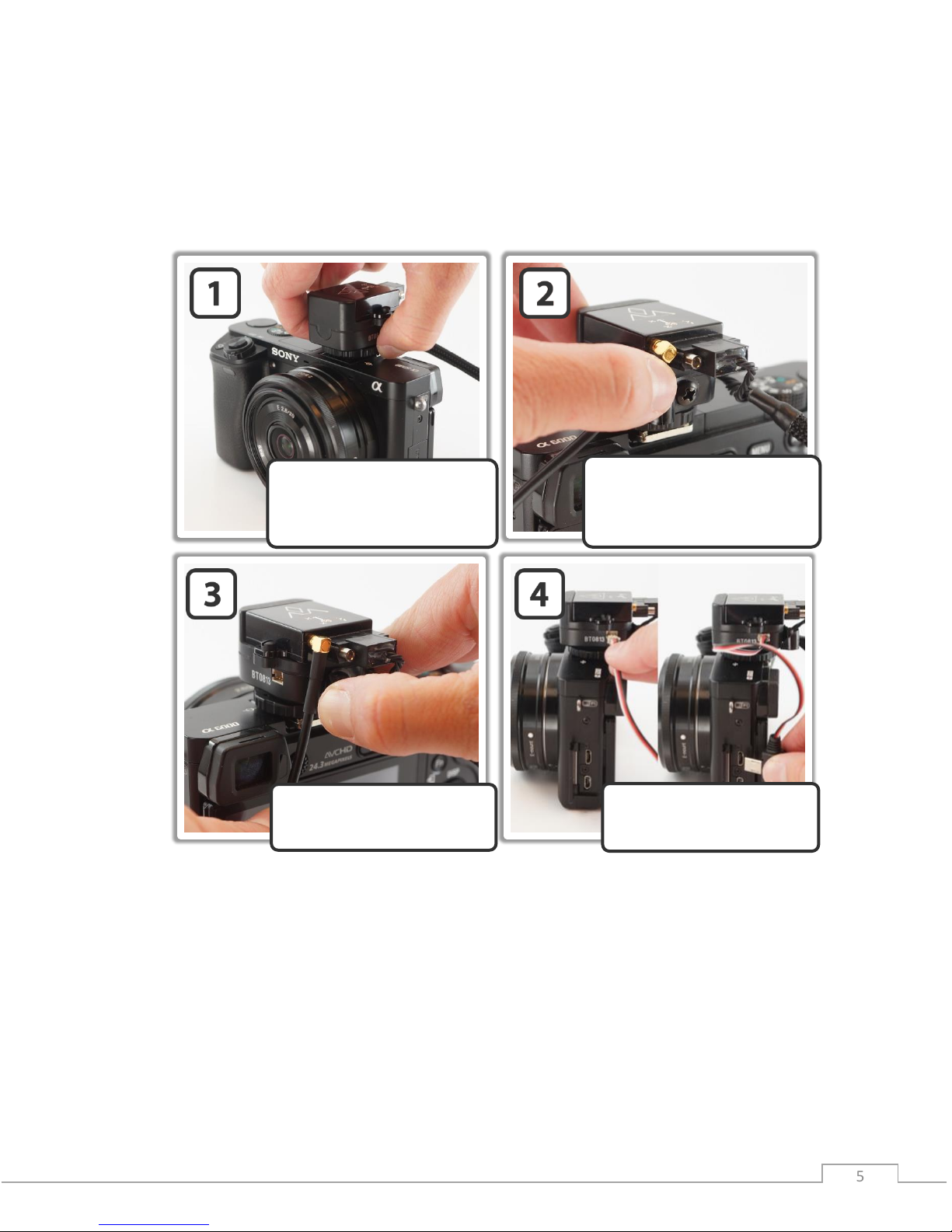
Installing the GeoSnap Pro on a DSLR-style Camera
Slide the hotshoe module onto
the hotshoe of the camera and
twist the lock ring clockwise
to tighten down the lock.
Pull back on the GPS antenna
strain relief and swivel the
GPS antenna cable into place.
Plug the GPS antenna’s MMCX
connector into the antenna port
on the VN-200 (press until it
clicks into place).
Plug the trigger cable into
the hotshoe module and the
camera trigger port.

© Field of View 2018 GeoSnap Pro User Manual
66
MOUNTING THE GPS ANTENNA
Make sure you mount the GPS antenna with the top facing up and with a clear view of the sky.
Also make sure that you do not mount the antenna near transmitters on the aircraft that could
cause interference and degrade the performance of the GPS.
Ground plane (optional)
To improve your GPS accuracy, it is recommended that you place a 10 cm diameter round or 10
cm x 10 cm square ground plane under the GPS antenna. This could be as simple as placing
some aluminum tape (that you can buy from a hardware store) around a piece of wood or
cardboard, sticking the antenna to the center of the plate, and attaching that whole assembly to
the top of your aircraft.
PIGTAIL TRIGGER CABLE
If you are not using a camera with a Sony multiport trigger connection, you will have been
provided with a 3-wire (green, white, black) pigtail trigger cable. When the GeoSnap system
sends a trigger command to the camera, it simply shorts the focus (white) and shutter release
(green) lines to ground (black). To make a trigger cable for your camera with this pigtail it is
recommended that you follow these steps:
1. Purchase a stock wired remote for your particular camera model.
2. Cut the stock remote cable 1-5” from the connector depending on the location of the
wired remote port relative to the GeoSnap hotshoe module.
3. Strip the ends of the stock remote cable wires.
4. Identify which cables in the stock cable relate to Ground, Focus, and Shutter Release.
5. Connect the wires to the provided pigtail trigger cable as follows: Ground -> Black, Focus
-> White, and Shutter Release -> Green.
6. Plug the cable into the camera and the GeoSnap hotshoe module as shown in steps 6
and 7 of the GeoSnap installation procedure above.
TOP

© Field of View 2018 GeoSnap Pro User Manual
77
Using the GeoSnap Pro
GEOSNAP FILES
There are various text files stored and/or logged on the microSD card. These files, and their
purposes, are described in this section.
Configuration File (CONFIG.txt)
The CONFIG file is where you can adjust all of the settings of the GeoSnap. Each time the
GeoSnap is powered, it searches for the configuration file and reads the settings. If this file is not
present, the GeoSnap creates a new configuration file with default options. For full descriptions
of all the settings in the CONFIG file, see the Configuration File section of this manual.
Image Log File (001-IMG.txt)
The IMG log file is a log of the image name and position/attitude of the camera at the moment
of image capture. Information is logged as plain, ASCII text in space-separated columns; each
column is 14 characters wide.
Image Log File Columns
Label
Units
Description
image
name
Image name/counter
gpsdate
YYYY-MM-DD
Date as reported by the VN-200
gpstime
HH:MM:SS.SSS
Time as reported by the VN-200
lat(deg)
degrees
Latitude as reported by the VN-200
lon(deg)
degrees
Longitude as reported by the VN-200
hght(wgs84-m)
meters
Height above WGS84 ellipsoid
roll(deg)
degrees
Roll as reported by the VN-200 (positive roll is a roll to the right)
pitch(deg)
degrees
Pitch as reported by the VN-200 (positive pitch is a pitch up)
yaw(deg)
degrees
Yaw as reported by the VN-200
gstime(ms)
milliseconds
GeoSnap time since power on
AttUncrt(deg)
degrees
Attitude uncertainty of the VN-200
PosUncrt(m)
meters
Position uncertainty of the VN-200
© Field of View 2018 GeoSnap Pro User Manual
88
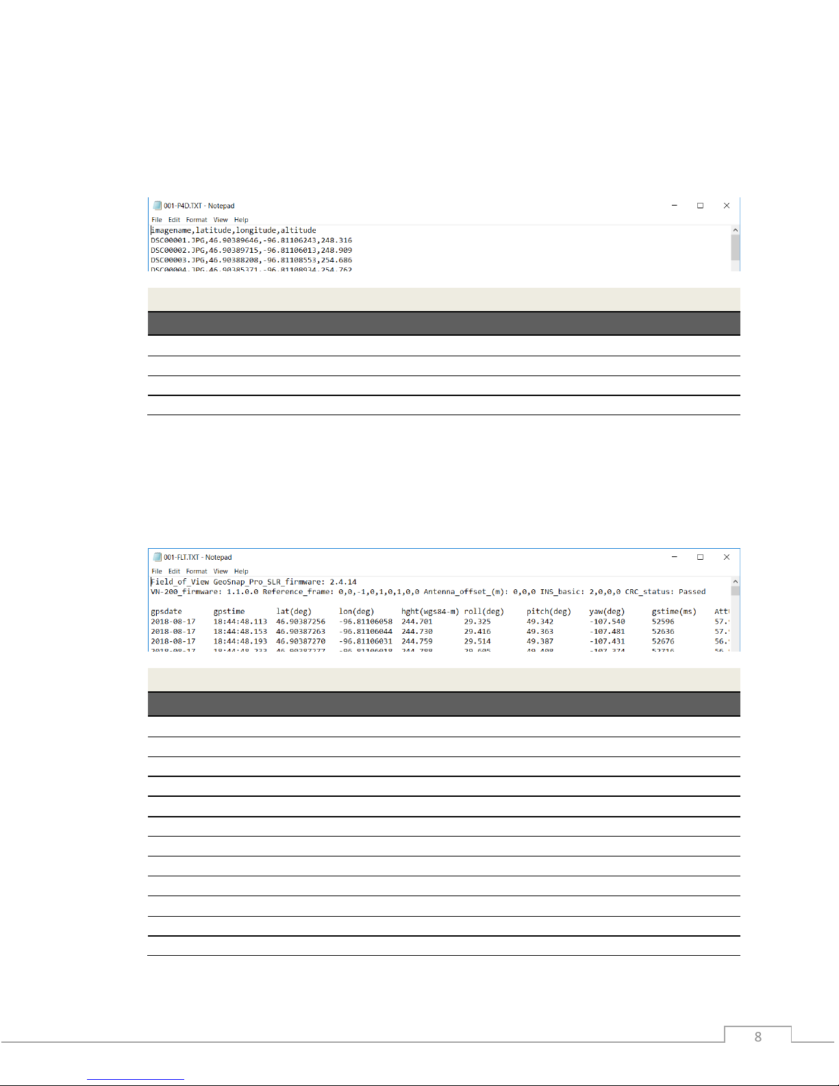
Pix4D Log File (001-P4D.txt)
The Pix4D log file is a Pix4D compatible log of the image name and position of the camera at the
moment of image capture. Information is logged as plain, ASCII text in comma-separated
columns.
Pix4D Log File Columns
Label
Units
Description
imagename
name
Image name/counter
latitude
degrees
Latitude as reported by the VN-200
longitude
degrees
Longitude as reported by the VN-200
altitude
meters
Height above WGS84 ellipsoid
Flight Log File (001-FLT.txt)
The FLT log file is a 25Hz log of the position/attitude of the camera throughout the flight. If the
log reaches 3 million lines a new FLT file is created with a letter appended to it using the
following convention: 001-FLT.txt, 001-FLTA.txt, 001-FLTB.txt, etc. Information is logged as plain,
ASCII text in space-separated columns; each column is 14 characters wide.
Flight Log File Columns
Label
Units
Description
gpsdate
YYYY-MM-DD
Date as reported by the VN-200
gpstime
HH:MM:SS.SSS
Time as reported by the VN-200
lat(deg)
degrees
Latitude as reported by the VN-200
lon(deg)
degrees
Longitude as reported by the VN-200
hght(wgs84-m)
meters
Height above WGS84 ellipsoid
roll(deg)
degrees
Roll as reported by the VN-200 (positive roll is a roll to the right)
pitch(deg)
degrees
Pitch as reported by the VN-200 (positivepitch is a pitch up)
yaw(deg)
degrees
Yaw as reported by the VN-200
gstime(ms)
milliseconds
GeoSnap time since power on
AttUncrt(deg)
degrees
Attitude uncertainty of the VN-200
PosUncrt(m)
meters
Position uncertainty of the VN-200
INS_stat
Status of the INS as reported by VN-200

© Field of View 2018 GeoSnap Pro User Manual
99
Imagenum File (IMAGENUM.txt)
This file keeps track of the numbering of the images in the IMG and Pix4D log files. To restart the
numbering at 1, simply delete the IMAGENUM file from the GeoSnap microSD card.
SYNCHRONIZING IMAGE NAMES
The GeoSnap does not get the actual image names from the camera but uses a sequential
numbering scheme in the specified image name format. Because of this, it is important that the
camera and the GeoSnap be set up so that they both start image numbering at 1 and remain
synchronized through use.
It is recommended to set the camera’s file numbering setting to Reset (for more information on
this, see the Camera Settings section of this manual). Then, before you start a new mission, clear
all images off the camera’s SD card and delete the IMAGENUM.txt file off the GeoSnap card. This
will reset both systems to start image numbering at 1.
CONFIGURING FOR MAPPING FLIGHTS
For mapping missions, we recommend setting up the GeoSnap to trigger the camera using the
distance interval option. The appropriate distance interval can be obtained from your flight
planning software, or from Field of View’s flight planning calculator, available at
fieldofviewllc.com/downloads. To configure the GeoSnap for distance interval triggering:
1. Insert the GeoSnap microSD card into a computer
2. Open the CONFIG.txt file using a text editor (e.g. Notepad)
3. Edit the following CONFIG file options to the specified settings, then save and replace
microSD card in the GeoSnap
@2: File_name = camera dependent (select the correct option for your camera)
@3: Trigger mode = 2
@5: Trigger_dist_m = your desired trigger distance interval in meters
@20: Antenna_offset_m = installation dependent (see the Configuration File
section of this manual for more information on how to properly use this option)
POWERING ON THE GEOSNAP
To power on the GeoSnap, simply plug in the provided USB power cable, or the power pigtail
cable connected to an appropriate power source (see the Specifications section of this manual
for power specifications). Before powering down the system, press and hold the onboard button
for approximately 3 seconds until all LED shine solid. This ends logging, making it safe to remove
power from the system.
Dynamic Motion
The VN-200 requires dynamic motion to reach full heading accuracy. Because of this, if you are
using the GeoSnap Pro on a multirotor, we highly recommend performing a few S-turns in
manual flight mode at the start of the flight before sending it on its autonomous mission.

© Field of View 2018 GeoSnap Pro User Manual
1010
LED CODES
The meanings of the LEDs on the GeoSnap board are explained in this section.
•Blue LED –This LED indicates when the board is powered. When power is sent to the
board, this LED shines solid.
•Red LED & Green LED –These LEDs indicate the status of the GeoSnap, including startup
status, GPS status, triggering, and camera capture indications.
Startup Sequence
LED Code
Meaning
Board is checking for access to the microSD card and writing a default
CONFIG file to the card if a CONFIG file does not already exist. *Note: this
is also the LED code for an SD card error (see below) so if this pattern
persists, check the SD card.
No GPS lock but system is ready to start operating. If the GeoSnap is
configured for fast as possible or time triggering, the first trigger
command will besent at this point
GPS lock. If the GeoSnap is configured for distance triggering, the first
trigger command will besent at this point.
Capturing Images
LED Code
Meaning
Trigger command sent.
Capture confirmation received from camera.
Shutdown
LED Code
Meaning
All data logging has stopped and it is safeto power down the system. This
occurs after pressing and holding the trigger button for approximately 3
seconds.
Errors
LED Code
Meaning
MicroSD card error. Occurs when there is no card, the card is not seated
properly, the card is full, or if the log file number exceeds 999.
© Field of View 2018 GeoSnap Pro User Manual
1111
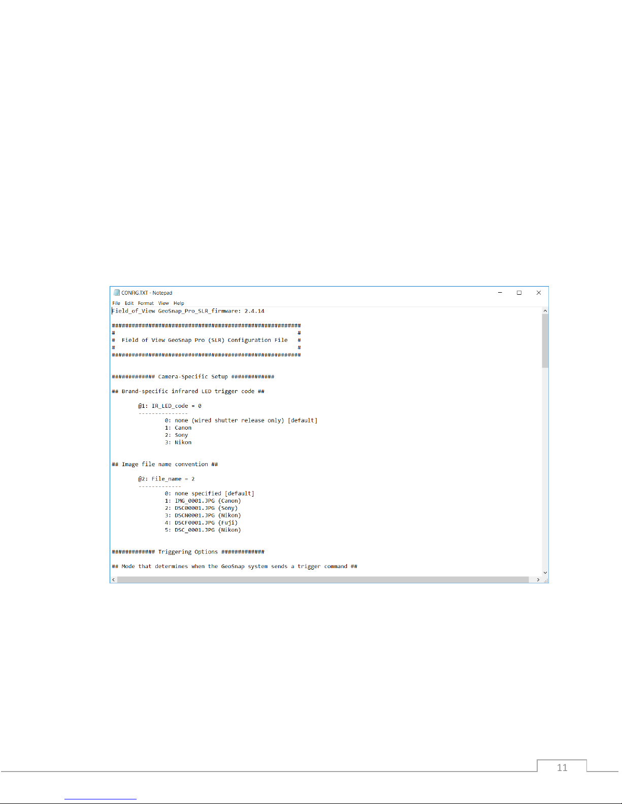
CONFIGURATION FILE
The CONFIG.txt file on the GeoSnap’s microSD card is where you can adjust all of the settings of
the GeoSnap. Each time the GeoSnap is powered, it searches for the configuration file and reads
the settings. If this file is not present, the GeoSnap creates a new configuration file with default
options.
The file consists of human-readable ASCII text and can be edited using many types of text
editors. On Windows, either Notepad or Wordpad may be used. On OSX, TextEdit may be used.
On GNU/Linux or Unix, EMACS, Vim, Nano, Pico, or other graphical equivalents may be used.
Note: word processing software such as Microsoft Word should not be used to edit the
configuration file.
The sections below describe in detail the various settings and how their options/values affect
the behavior of the GeoSnap.

© Field of View 2018 GeoSnap Pro User Manual
1212
Brand-specific infrared LED trigger code
Default String:
@1:IR_LED_code = 0
Values:
0: none (wired shutter release only) [default]
1: Canon
2: Sony
3: Nikon
Description:
If you are using a wired trigger cable to trigger the camera, you can keep this value at the
default option ‘0’. This option was used to control the IR code that is output by the GeoSnap
to trigger the camera via an IR trigger cable (this cable is no longer provided standard with
the GeoSnap due to wired triggering being more reliable).
Image file name convention
Default String:
@2:File_name = 0
Values:
0: none specified [default]
1: IMG_0001.JPG (Canon)
2: DSC00001.JPG (Sony)
3: DSCN0001.JPG (Nikon)
4: DSCF0001.JPG (Fuji)
5: DSC_0001.JPG (Nikon)
Description:
This option allows you to specify what will be entered into the “image” column in the image
log file and Pix4D log file. If option ‘0’ is selected, the “image” entry in the log file will be
filled with a counter that can be converted to image names in post-processing using
Geotility. If an actual image name is selected the “image” entry in the image log file will be
filled with consecutively numbered image names. For example, if option ‘1’ is selected, the
entries in the “image” column will take the form of IMG_0001.JPG, IMG_0002.JPG, etc.

© Field of View 2018 GeoSnap Pro User Manual
1313
Mode that determines when the GeoSnap system sends a trigger
command
Default String:
@3:Trigger_mode = 0
Values:
0: onboard button only [default]
1: time
2: distance
3: fast-as-possible
4: low->high input signal
5: high->low input signal
6: low->high and high->low input signal
7: Garmin portable aviation GPS waypoint arrival/time interval
Description:
Set this option to specify the camera triggering mode of the GeoSnap.
•Onboard button only: a trigger command is sent when the GeoSnap’s onboard
button is pushed.
•Time: trigger commands are sent at a uniform time interval that is specified in the
time interval option.
•Distance: trigger commands are sent at a uniform distance interval (calculated from
the latitude and longitude obtained from the GPS) that is specified in the distance
interval option.
•Fast-as-possible: a trigger command is sent immediately after the GeoSnap receives
capture verification from the camera from the prior trigger command.
•Input signal modes (options 4, 5, and 6): a trigger command is sent every time the
GeoSnap receives an external input signal as listed in the option. For example, if
‘low->high input signal’ is selected, the GeoSnap will send a trigger command to the
camera every time the external input signal transitions from low to high voltage (for
more information on using an external input signal, see the External Connections
section of this manual).
•Garmin portable aviation GPS waypoint arrival/time interval (legacy feature): a
trigger command is sent every time a waypoint that is set in a Garmin portable
aviation GPS is reached. It will also send a trigger command at the specified time
interval when the switch on the handheld remote (part of the Garmin portable
aviation GPS GeoSnap solution) is in the always on position.

© Field of View 2018 GeoSnap Pro User Manual
1414
For mode 1 or 7 above, specify a time interval in seconds
Default String:
@4:Trigger_time_sec = 2.0
Values:
0.1 - 64800 seconds (in tenth of a second increments)
Description:
This option sets the amount of time (in seconds) between trigger commands sent by the
GeoSnap when it is set to time mode triggering (or when the handheld remote switch is set
to the always on position in a Garmin setup). This is configurable in tenth of a second
increments. The trigger mode must be set to 1 or 7 in order for this option to have any
effect on system operation.
For mode 2 above, specify a distance interval in meters
Default String:
@5:Trigger_dist_m = 50
Values:
1 - 10000 meters (in meter increments)
Description:
This option sets the distance (in meters) between trigger commands sent by the GeoSnap
when it is set to distance mode triggering. This is configurable in meter increments. Any
decimals entered will be truncated. The trigger mode must be set to 2 in order for this
option to have any effect on system operation.
Length of time the GeoSnap system waits for capture verification from
the camera before resending the trigger command
Default String:
@6:Resend_trig_time_ms = 500
Values:
0 - 60000 milliseconds
Description:
This option allows you to set the amount of time the GeoSnap waits for capture verification
before resending the trigger command. This option gives you control over your mission
quality control by allowing you to specify the amount of time to wait and see if the camera
took a picture before identifying a missed trigger and attempting to salvage the trigger
point.

© Field of View 2018 GeoSnap Pro User Manual
1515
Use external input signal or onboard button to control time mode, fast-as-
possible mode, and/or distance mode
Default String:
@7:Control_mode= 0
Values:
0: feature disabled [default]
1: high input signal enables time mode, fast-as-possible mode, or
distance mode
2: low input signal enables time mode, fast-as-possible mode, or
distance mode
3: onboard button starts time mode or fast-as-possible mode
4: onboard button toggles (starts/stops) time mode or fast-as
possible mode
Description:
This option allows you to use an external input signal to enable time mode, fast-as-possible
mode, or distance mode; or to use the GeoSnap onboard button to start and/or stop time
mode or fast-as-possible mode. If this feature is disabled and the GeoSnap is in time, or fast-
as-possible mode, it will start sending trigger commands as soon as it is powered. If this
feature is disabled and the GeoSnap is in distance mode, it will start sending trigger
commands as soon as a GPS lock is acquired.
If one of the input signal options (1 or 2) is selected, time, distance, or fast-as-possible
triggering will only be allowed when the external input signal is held high or held low
(depending on the option selected). This is useful if images are only desired during a certain
portion of the flight.
If option 3 is selected, time or fast-as-possible triggering won’t start until the button is
pressed, and subsequent button presses will be ignored. If option 4 is selected, time or fast-
as-possible triggering won’t start until the button is pressed and subsequent button presses
will stop and start the triggering.
Activate time mode or fast-as-possible mode when the GeoSnap system
detects an initial image capture
Default String:
@8:Initial_image_activation = 0
Values:
0: feature disabled [default]
1: feature enabled

© Field of View 2018 GeoSnap Pro User Manual
1616
Description:
This option configures whether to start time or fast-as-possible triggering after an initial
camera image capture has been detected by the GeoSnap. This initial image capture could
be initiated using the shoulder button on the camera or with an external signal input.
Send trigger command at least every X minutes to prevent camera live-
view timeout
Default String:
@9:Elapsed_time_min = 0
Values:
0 –600000 min
Description:
This option is designed for use with a manned aircraft setup with Canon Live-View. The
Canon camera kicks out of Live view mode after a period of inactivity. This option allows you
to have the GeoSnap keep track of length of inactivity (i.e. no camera triggers) and send a
trigger command at the specified number of minutes if no activity has happened. For
example, if you set the value to 10 and there were no images taken after 10 minutes, the
GeoSnap would command a trigger at that point. To disable this feature, simply set the
value to 0.
Only allow time mode, distance mode, or fast-as-possible mode within
specified pitch/roll angles
Default String:
@10:Enable_PR_limit = 0
Values:
0: feature disabled [default]
1: feature enabled
Description:
This option allows you to constrain the GeoSnap so that it pauses image triggering when the
aircraft pitches or rolls beyond a specified limit. For example, when the roll limit is set to 45
degrees, the GeoSnap will not send a trigger command at any time that the VN-200 is
outputting roll values greater than or equal to 45 degrees or less than or equal to -45
degrees. A trigger not sent due to aircraft attitude is sent as soon as the attitude falls within
the set limits.

© Field of View 2018 GeoSnap Pro User Manual
1717
Roll limit
Default String:
@11:Roll_limit_deg = 45
Values:
0 –180 degrees (to the nearest degree)
Description:
This option configures the roll limit associated with Pitch/Roll limit option. The Pitch/Roll
limit option must be enabled for this to take effect. This is configurable in one degree
intervals only. Any decimals entered will be truncated.
Pitch limit
Default String:
@12:Pitch_limit_deg = 45
Values:
0 –90 degrees (to the nearest degree)
Description:
This option configures the pitch limit associated with Pitch/Roll limit option. The Pitch/Roll
limit option must be enabled for this to take effect. This is configurable in one degree
intervals only. Any decimals entered will be truncated.
Only allow time mode, distance mode, or fast-as-possible mode above a
specified WGS84 altitude
Default String:
@13:Enable_altitude_limit = 0
Values:
0: feature disabled [default]
1: feature enabled
Description:
This option allows you to constrain the GeoSnap so that it pauses image triggering when the
aircraft is below a certain WGS-84 altitude. This is useful to prevent image capture while the
aircraft is on the ground.

© Field of View 2018 GeoSnap Pro User Manual
1818
WGS84 altitude limit
Default String:
@14:Minimum_altitude_m = 50
Values:
1 - 65536 meters (to the nearest meter)
Description:
This option configures the altitude limit associated with the altitude limit option. The
altitude limit option must be enabled for this to take effect. This is configurable in one
meter intervals only. Any decimals entered will be truncated.
Associate and log position/attitude data at the moment the trigger
command is sent, not when capture verification is received
Default String:
@15:Blind_logging = 0
Options:
0: feature disabled [default]
1: feature enabled
Description:
This option allows you to ignore capture verification completely and associate and log
position/attitude data at the time that the trigger command is sent. Since capture
verification is ignored when blind logging is enabled, if you are in fast-as-possible mode the
GeoSnap will send a trigger command at the interval specified in the Resend_trig_time_ms
option (option @6).
Associate position/attitude data with the image ‘x’ milliseconds after
capture verification is received
Default String:
@16:Association_delay_ms = 0
Description:
This option allows you to add a delay between when the GeoSnap received capture
verification and when the position/attitude association is performed and written to the
image log file.

© Field of View 2018 GeoSnap Pro User Manual
1919
Select which log files to generate
Default String:
@17:Data_logging = 0
Options:
0: generate image log, pix4d log, and flight data log [default]
1: generate image log and flight data log only
2: generate image log and pix4d log only
3: generate image log only
Description:
This option configures whether or not to create and populate the IMG, P4D, and/or FLT log
files on the GeoSnap’s microSD card.
VN-200 orientation relative to the camera
Default String:
@18:VN_orientation = 0
Options:
0: default orientation [default]
1: custom orientation
Description:
Use this option to select the orientation of the VN-200 relative to the camera. The default
orientation (0,0,-1,0,1,0,1,0,0) is appropriate for the standard GeoSnap installation on the
hotshoe of the camera. In this orientation the X-axis of the VN-200 and the camera lens are
pointing in the same direction, with the Z-axis of the VN-200 pointing down out of the
bottom of the camera. If the VN-200 is mounted in a different orientation relative to the
camera, select option 1 and specify the appropriate reference frame rotation in the
following option.
For option 1 above, specify the reference frame rotation for the VN-200
Default String:
@19:Reference_frame = 0,0,-1,0,1,0,1,0,0
Values:
C00,C01,C02,C10,C11,C12,C20,C21,C22
is translated to

© Field of View 2018 GeoSnap Pro User Manual
2020
Description:
This input defines the transformation matrix required to align the body frame of the VN-200
to the camera frame of reference. This allows for the VN-200 to be placed in any arbitrary
orientation with respect to the camera. The default string is the appropriate string for the
standard mounting configuration of the VN-200 on the GeoSnap hotshoe module.
The variables {X, Y, Z}Bare a measured parameter in the body reference frame with respect
to the VN-200. The variables {X, Y, Z}Care a measured parameter in the camera’s frame of
reference.
GeoSnap performs an internal transformation to assign the standard aircraft coordinate
system to the camera so that the Z-axis is pointing out of the lens, the X-axis is off of the top
of the camera, and the Y-axis is off of the right of the camera. This can be seen below.
The matrix equation translates to the following three linear equations:
Y
X
Z
Other manuals for GeoSnap Pro
1
Table of contents
Other FIELD OF VIEW Camera Accessories manuals


