CyberPower BPE240V30ART3U User manual

User’s Manual
EXTENDED BATTERY MODULE (EBM)
BPE240V30ART3U
BPE240V50ART3U
Cyber Power Systems,Inc.
www.cyberpower.com
K01-0000209-02

Copyright © 2017 Cyber Power Systems, Inc.
OVERVIEW
1
The CyberPower Battery modules (BPE240V30ART3U / BPE240V50ART3U) support 30A/50A polarized plugs, and are designed for variety of Cyber Power
UPS systems. When combining with the UPS, the Battery module provides extended runtime with a 240VDC external connection. Additional
parallel-connected Battery modules provide the UPS for a longer extended runtime operation.
Battery module
User’s manual Register card
Rackmount left rail Rackmount right rail
Left hanging bracket Right hanging bracket
Power cord
Rackmount ears (Stands) (2)
Tie plate
Flat head screws:M5X7L (8)
Pan head screws:M5X12L (4)
Pan head screws:M5X6L (14)
Guide screws:M5X10L (2)
Plastic washers (8)
Screw hole dust covers (14)
Rubber feet (4)
UNPACKING

Copyright © 2017 Cyber Power Systems, Inc.
HARDWARE INSTALLATION
2
HARDWARE INSTALLATION
These versatile EBM can be mounted in a rackmount or vertical tower
orientation. This versatility is especially important to growing
organizations with changing needs that value having the option to
position a EBM on a floor or in a rackmount system. Please follow the
instructions below for the respective mounting methods.
SAFETY PRECAUTIONS
CAUTION! To prevent the risk of fire or electric shock, only use the
supplied hardware to attach the mounting brackets.
RACKMOUNT INSTALLATION
Step 1: Remove the dust covers
Remove the dust covers *10pcs from the screw holes.
Step 2: Rackmount ears & hanging brackets installation
Attach two rackmount ears to the EBM using the provided M5X7L*8pcs
screws and tighten two hanging brackets with the M5X6L*6pcs screws.
Step 3: Rackmount rail Installation
The rails adjust to mount in 48-cm (19-inch) panel racks from 52 to
91.5cm (20.5 to 36 inches) deep. Select the proper holes in the rack for
positioning the EBM in the rack. The EBM takes up position 1 through 9.
Position the guide screws on the rails into the rear rack square holes to
temporarily support the rails in place. Tighten the front rail screws on the
rack.

Copyright © 2017 Cyber Power Systems, Inc.
3
HARDWARE INSTALLATION
Step 4: Adjust rackmount rails to fit your rack
Adjust the rail depth to match your rack depth. Attach the rackmount rail
to your rack with two screws and two plastic washers at the front of the
rack. (Located in position 4 & position 8) Tighten the M5X6L screws on
the front bracket. Secure the rail to the rear of the rack with two M5X6L
screws and two plastic washers.
Step 5: Place and secure the UPS on the rails
Slide the hanging brackets on the UPS into the rails mounted in the rack
with the front of the unit facing toward you. Secure the UPS to your rack
with four M5X12L*4pcs screws at the front of the rack. (Located in
position 5 & position 7)
How to Slide out UPS from rail
The Battery pack will be secured by a safety locking mechanism midway
of pulling it out of the rack. Use both hands to hold the Battery pack and
press the safety locking tab to pull the Battery pack out.

Copyright © 2017 Cyber Power Systems, Inc.
HARDWARE INSTALLATION
4
VERTICAL/TOWER INSTALLATION
Step 1: Adhere the rubber feet on the bottom side of base stands
Adhere the protective rubber feet on the bottom side of UPS and EBM.
Step 2: Attach the base stands and attach the dust covers
Secure the tie bracket with the screws (M5X7*4pcs). Insert dust covers
into the screw holes that are not being used.
Step 3: Rotate the Multifunction LCD Module
Unscrew the upper panel of the UPS. Separate the upper panel from the
UPS. Gently lift the LCD module out. Rotate it to the tower orientation.
Reinstall it for a tower configuration.
ELECTRICAL INSTALLATION
After completing the hardware installation of the UPS, you are now ready
to plug in the UPS and connect your equipment.
SAFETY PRECAUTIONS
CAUTION! Installation environment should be in a temperature and
humidity controlled indoor area free of conductive contaminants. Do not
install this EBM where excessive moisture or heat is present (Please see
specifications for acceptable temperature and humidity range).
CAUTION! Never install an EBM, or associated wiring or equipment,
during a lightning storm.
CAUTION! Do not work alone under hazardous conditions.
CAUTION! In case of the risk of electric shock, do not remove the top
cover.
CAUTION! The battery can energize hazardous live parts inside even
when the AC input power is disconnected.

Copyright © 2017 Cyber Power Systems, Inc.
5
BASIC OPERATION
BATTERY MODULE FRONT/REAR PANEL DESCRIPTION
1. On-board Replaceable Fuse Cover
Replaceable fuse is accessible from the rear panel. It must
be done by qualified personnel.
2. AC Circuit Breaker
Provides overload and fault protection.
3. AC Output Outlet
Use this outlet to connect to the AC Input Inlet of a
downstream Battery module.
4. AC Input Inlet (Charge Only)
AC power connectivity to wall receptacle.
5. Input Connector
Use this input connector to daisy chain the next Battery
module. Remove the connector cover for access.
6. Output Cable
Use this output cable to connect the Battery module to the
Power module or to the next Battery module.
BPE240V30ART3U / BPE240V50ART3U
CONNECTION #1 : POWER MODULE WITH ONE BATTERY MODULE
Step 1: Loosen the two screws to remove the battery cable
retention bracket of the power module.
Step 2: Use the output cable of the Battery module to connect
the Battery module to the Power module.
Step 3: Rotate the battery cable retention bracket and tighten
the two screws to fix battery cable.
Step 4: Use a power cord to plug AC input inlet of the battery
module into a wall receptacle.

Copyright © 2017 Cyber Power Systems, Inc.
BASIC OPERATION
6
CONNECTION #2 : POWER MODULE WITH MULTIPLE BATTERY MODULES
Step 1: Connect the 1st Battery module to the Power module
using the instructions above.
Step 2: Loosen the two screws to remove the battery cable
retention bracket of the 1st battery module.
Step 3: Use the output cable of the 2nd Battery module to
connect the 2nd Battery module to the 1st Battery
module.
Step 4: Rotate the battery cable retention bracket and tighten
the two screws to fix battery cable.
Step 5: Use a power cord to plug AC input inlet of the 2nd battery
module into AC output outlet of the 1st Battery module.

Copyright © 2017 Cyber Power Systems, Inc.
7
BASIC OPERATION
EXTERNAL BATTERY MODULES CONFIGURATION
External Battery Modules can be configured by the user to display correct estimated battery runtimes.
1. Press the “ENTER” button to activate the “MAIN MENU”.
2. Press the “▲”and “▼”buttons to scroll to the “Configure”option.
3. Press the “ENTER” button to select the “Configure”submenu.
4. Press the “▲”and “▼”buttons to scroll to the “EBP Number”option.
5. Press the “ENTER” button to select the “EBP Number”submenu.
The first configuration number will be displayed on the second column of LCD display.
6. Press the “▲”and “▼”buttons to scroll through the number of attached Battery modules.
7. Press the “ENTER” button to select the number of Battery modules installed.
You may be prompted to save the selection, if so press the “ENTER” button to save the setting.
8. Press the “ESC” button to cancel or return to the previous LCD menu.
Configure Submenu
Available Settings
Default Settings
EBM Number
= [0] [1] [2] [3] [4] [5] [6] [7] [8] [9] [10]
0

Copyright © 2017 Cyber Power Systems, Inc.
MAINTENANCE
8
Storage
To store your UPS for an extended period, cover it and store with the
battery fully charged. Recharge the battery every three months to ensure
battery life.
Battery Replacement
Please read and follow the Safety Instructions before servicing the
battery. Battery replacement should be performed by trained personnel
who are familiar with the procedures and safety precautions. Make a note
of the replacement Battery module number.
Safety Precautions
CAUTION! Only use replacement batteries which are certified by
Cyber Power Systems. Use of incorrect battery type is an electrical
hazard that could lead to explosion, fire, electric shock, or short circuit.
CAUTION! Batteries contain an electrical charge that can cause
severe burns. Before servicing batteries, please remove any conductive
materials such as jewelry, chains, wrist watches, and rings.
CAUTION! Do not open or mutilate the batteries. Electrolyte fluid is
harmful to the skin/eyes and may be toxic.
CAUTION! To avoid electric shock, turn off and unplug the Battery
module from the wall receptacle before servicing the battery.
CAUTION! Only use tools with insulated handles. Do not lay tools or
metal parts on top of the UPS or battery terminals.
Replacement Batteries
Please refer to the front side of the Battery module for the model number
of the correct replacement batteries. For battery procurement, log onto
www.CPSww.com, or contact your local dealer.
Battery Disposal
Batteries are considered hazardous waste and must be disposed of
properly. Contact your local government for more information about
proper disposal and recycling of batteries. Do not dispose of batteries
in fire.
Cyber Power Systems encourages environmentally sound methods for
disposal and recycling of its UPS products.
Please dispose and/or recycle your UPS and batteries in accordance to
the local regulations of your state.
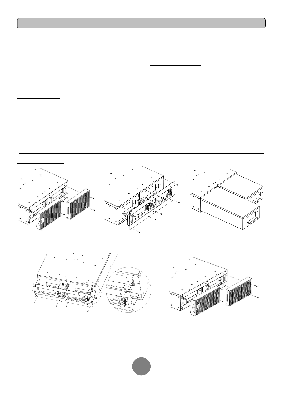
Battery Replacement
Step 1: Remove the front panels Step 2: Remove the retaining screws from
the cable protection cover and then remove
the cover itself
Step 3: Pull the battery trays out slowly and
then put the new battery trays back into the
compartment
Step 4: Insert the battery connectors and tighten the screws of
battery retaining cover
Step 5: Install the front panels, then to execute battery
test via the LCD control panel, go to the Configuration
Menu, then scroll to the UPS Diagnostic then select
battery test and Activate, then scroll to Reset ReplaceBAT
to reset the battery replacement date. This operation can
also be done via PowerPanel® Business Edition Agent or
RMCARD web interface if it is installed. Please see their
respective User Manuals for detailed instructions.

Copyright © 2017 Cyber Power Systems, Inc.
TECHNICAL SPECIFICATIONS
9
Cyber Power Systems,Inc.
www.cyberpower.com
Entire contents copyright©2017 Cyber Power Systems,Inc., All rights reserved. Reproduction in whole or in part
without permission is prohibited. PowerPanel®Business Edition and PowerPanel®Personal Edition are trademarks of
Cyber Power Systems Inc.
Model
BPE240V30ART3U
BPE240V50ART3U
Configuration
AC Input Voltage
180~280Vac
DC Output Voltage
240Vdc
Amperage
33A
55A
Physical
Dimensions
L x W x H = 26 x 17 x 5.2in. (660 x 433 x 132mm)
Net Weight
167.2lbs(76Kg)
171.6lbs(78Kg)
Battery
Specifications
(20) 12V/7.2AH
(20) 12V/9.0AH
Recharge Time (Typically)
4 hours
5 hours
Interface
PP45
Sealed, Maintenance Free
Yes
Hot-Swappable
Yes
Built-in Charger
Yes
Environment
Operating Temperature
32℉to 104℉( 0℃to 40℃)
Operating Relative Humidity
0 to 90% Non-Condensing
Safety
Conformance Approvals
CE, C-tick
RoHS
RoHS Compliant
Warranty
Product Warranty
3-year limited warranty, Free Tech Support
Problem
Possible Cause
Solution
Warning
BAT Disconnected
Missing battery power.
Check battery connector and battery breaker.
Battery Failure
UPS has failed in Battery Test.
1. Check battery connector and battery breaker.
2. Contact technical support to replace the
battery.
Replace Battery
Battery will soon need to be replaced due to
insufficient runtime.
Contact technical support to replace the battery.
Fault
Over Charge
Battery is overcharged.
1. Remove battery connector and check
charger voltage.
2. Contact CyberPower for repair.
Charger Failure
Charger has failed.
TROUBLE SHOOTING
Other manuals for BPE240V30ART3U
1
This manual suits for next models
1
Table of contents
Other CyberPower Camera Accessories manuals

CyberPower
CyberPower BPE240V30ART3U User manual

CyberPower
CyberPower BPL48V75ART2U User manual

CyberPower
CyberPower BPSE240V75ART3U User manual

CyberPower
CyberPower DT30U12V-NA3 User manual

CyberPower
CyberPower CST625G User manual

CyberPower
CyberPower SE450G1 User manual

CyberPower
CyberPower BP240V30ART3U User manual