iO HVAC Controls ZP6-ESP-PRO User manual

UNIVERSAL 2-POSITION
FORCED AIR ZONING SYSTEM
Installation Guide
ZP6-ESP-PRO
Indianapolis, IN 46237


TABLE OF CONTENTS
Overview .................................................................................................................... 2
Sequence of Operation ............................................................................................... 2
Design and Installation Guidelines .............................................................................. 2
ZP6-ESP-PRO Panel Layout .............................................................................................3
System Wiring .......................................................................................................... 4-8
Warning! ........................................................................................................... 4
Caution! ............................................................................................................ 4
System Power .................................................................................................... 4
HVAC System .................................................................................................... 4
Heat/Cool ............................................................................................... 4
Heat Pump .............................................................................................. 4
DS/BK Option .......................................................................................... 5
HUM Option ........................................................................................... 5
DHUM Option ......................................................................................... 5
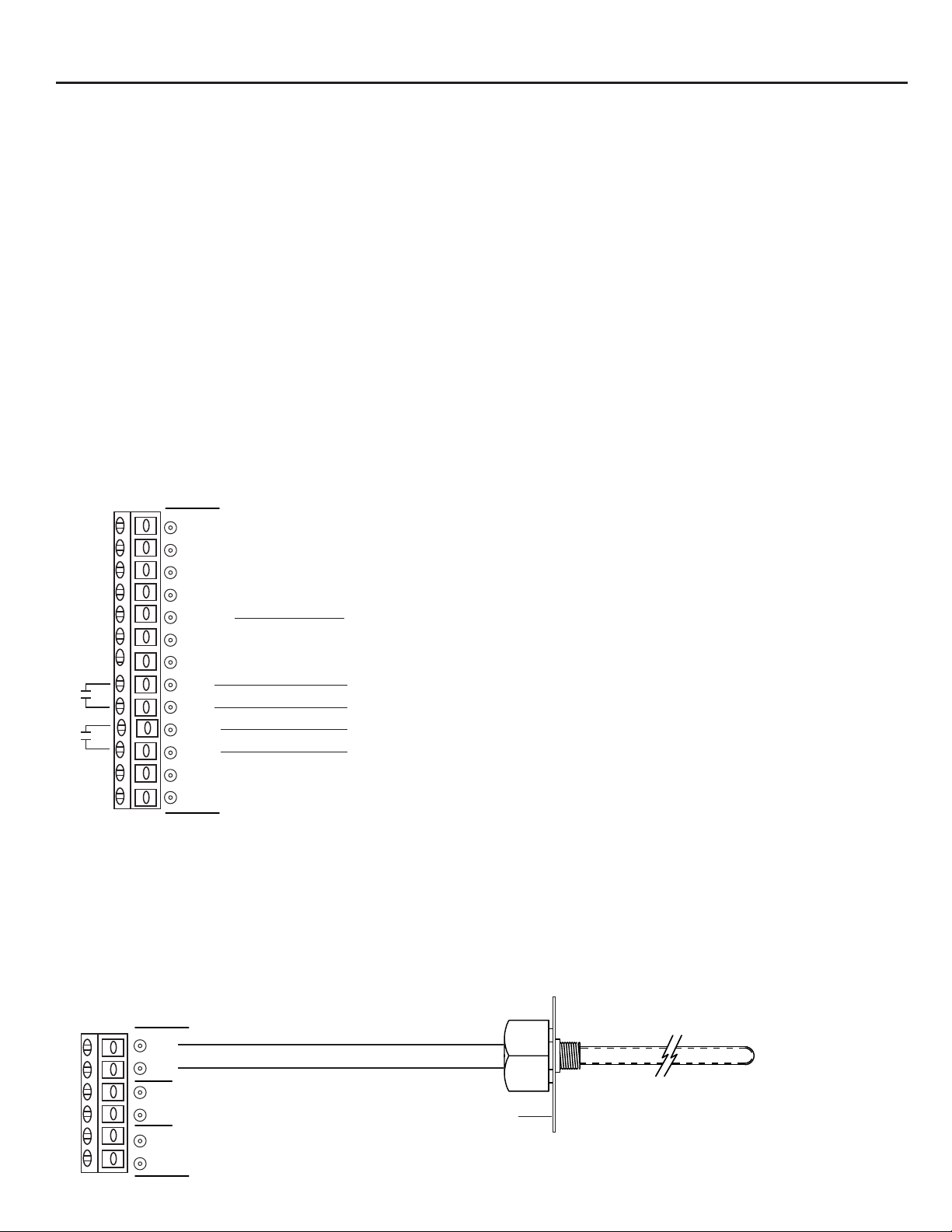
Sensors .......................................................................................................... 5-6
Discharge Air Sensor .............................................................................. 5
Return Air Sensor .................................................................................... 6
Outdoor Air Sensor ................................................................................. 6
Night Stat Option .............................................................................................. 6
Fault Terminals .................................................................................................. 7
Zone Thermostats ........................................................................................... 7-8
Heat/Cool ............................................................................................ 7
Heat Pump ........................................................................................... 7-8
Zone Dampers .......................................................................................... 8
SPS Terminals.............................................................................................9
How ESP Works................................................................................9
Adding 3-Zone Expansion Panels................................................................................ 10
Panel Setup ......................................................................................................... 11-12
Switch Congurations ...................................................................................... 11
System Conguration ............................................................................ 11
Capacity Control .................................................................................. 12
DS/BK Control ..................................................................................... 12
Graphic Display Module ........................................................... 12
Setting High Limit ........................................................................ 12
Setting Low Limit ......................................................................... 13
Setting High Balance Point .......................................................... 13
Setting Low Balance Point ........................................................... 14
Upstage Timer Option ................................................................. 14
Selecting ESP Zones .......................................................................15
Panel LED Denitions and Functions ........................................................... 16-17
Panel Time Delays ..................................................................................................... 17
Optional Night Stat Setup and Scheduling ............................................................ 18-19
Overview ...................................................................................................... 18
How It Works ................................................................................................... 18
Recommended Setup ....................................................................................... 18
System Switch Settings ..................................................................................... 18
Installer Setup Menu Changes ......................................................................... 18
Setting the Clock and Day of Week .................................................................. 19
Daylight Saving Time ....................................................................................... 19
Programming Events ................................................................................... 19-20
Typical 7-Day Schedule .................................................................................. 20
Notes ........................................................................................................................ 21
1

OVERVIEW
The ZP6-ESP-PRO is a residential and light commercial forced air zone control systems that allows
a single HVAC unit to have up to 6 separate zones. The system can be expanded to as many as 12
zones by adding 3-zone expansion panels. The panel can be used with single stage or multi-stage
heat/cool equipment as well as heat pump and duel fuel systems having up to 4 stages of heating
and 2 stages of cooling. Simple slide switch congurations allow for a wide range of system setup
and control options best suited for each zoning application. The ZP6-ESP-PRO incorporates an
integrated ESP static pressure control logic designed to eliminate the need for a conventional
bypass damper when used with 3-wire zone dampers. A Graphics Display Module (GDM) allows
real time monitoring of discharge air, return air and outside air temperature when used with
appropriate sensors. The GDM is also used to set high and low limits, high and low outdoor
balance points, timed upstaging and selection of designated ESP zones.
SEQUENCE OF OPERATION
Each zone is controlled by its own space thermostat and motorized zone damper. If any zone
thermostat calls for heating or cooling, the zones not calling will have their dampers powered
closed and the zones calling will have their dampers powered open. The heating or cooling
equipment will be brought on at the same time. When all zones are satised, the heating or
cooling equipment turns off. Zone dampers then reposition based on ventilation mode selection.
The system can be set up to operate in either Cooling Priority or Majority Wins mode of
operation.
COOLING PRIORITY:
When zones call for heating and cooling at the same time, cooling will receive priority and the
system will operate in the cooling mode until all cooling calls are satised and then automatically
change over to satisfy heating calls.
MAJORITY WINS:
If more zones call for heating than cooling, the system will be in the heating mode. If more zones
call for cooling than heating, the system will be in the cooling mode. If the number of heating and
cooling calls are equal, cooling wins.
DESIGN AND INSTALLATION GUIDLINES
2
[ ] Zone control begins with good HVAC design.
[ ] Proper load calculations used to determine duct and equipment sizing are essential in achieving
optimum performance.
[ ] Install zone thermostats in their respective zones.
[ ] System wires should be tagged to match the panel terminal designations and zone
identication.
[ ] Zone dampers should be installed at least 10’ back from discharge air grills whenever possible.
[ ] Zone dampers need to be located where they can be accessed for trouble shooting.
[ ] Flex or lined duct is recommended on the last 5’ of each branch run.
[ ] Thermostats and zone dampers can typically be located up to 300’ from the control panel when
18AWG copper thermostat wire is used.
[ ] Always use a separate 24VAC transformer rated at the proper VA to power the panel, zone
dampers and thermostats.
[ ] Never use the equipment transformer regardless of its VA rating.
[ ] When using forced air zoning with a variable speed HVAC system, high speed fan should be set
at 400 CFM per ton of cooling.

ZP6-ESP-PRO PANEL LAYOUT
3
SELECT UP DOWN
3 AMP3 AMP
3 AMP 3 AMP
3 AMP
602ZP-ESP
24 VOLT POWER
ZONE 1 DAMPER
ZONE 2 DAMPER
ZONE 3 DAMPER
ZONE 4 DAMPER
ZONE 5 DAMPER
ZONE 6 DAMPER
OPTIONAL NIGHT STAT
STATIC PRESSURE SENSOR
DISCHARGE AIR SENSOR
RETURN AIR SENSOR
OUTDOOR SENSOR
EQUIPMENT FAULT INPUT
HVAC EQUIPMENT
ZONE 1 THERMOSTAT
ZONE 2 THERMOSTAT
ZONE 3 THERMOSTAT
ZONE 4 THERMOSTAT
ZONE 5 THERMOSTAT
ZONE 6 THERMOSTAT
EXPANSION BOARD CONNECTOR 3 AMP FUSES
PROTECT RELAY
CONTACTS
3 AMP FUSE
PROTECTS CIRCUIT
BOARD
SYSTEM
SETUP
SWITCHES
TIME DELAY
SPEED UP
BUTTON
SYSTEM
STATUS
LEDs
HVAC
SYSTEM
LEDs
ZONE
DAMPER
POSITION
LEDs
(ON WHEN
OPEN)
OCCUPIED
LED
GRAPHIC
PROGRAMMING
DISPLAY MODULE
Rev 1
PC2
C1
PO3
PC2
C1
PO3
PC2
C1
PO3
PC2
C1
PO3
PC2
C1
PO3
PC2
C1
PO3

SYSTEM WIRING
WARNING!
1. Turn power off to HVAC equipment and control panel during installation to prevent serious injury
from electrical shock and/or damage to the system.
2. Use extreme care when making duct openings and handling sheet metal to avoid injury.
3. Install all components in a manner that provides easy access for test, check, and startup.
CAUTION!
1. Installation of this system must be in compliance with all applicable codes.
2. HVAC system must be properly sized and balanced to assure optimum system performance.
3. All low voltage cable must be 18 gauge solid (not stranded) wire.
4. All wiring should be color coded and tagged for proper identication.
iO-ZP6-ESP-PRO PANEL WIRING
System Power
1. Wire a 24VAC, 75VA transformer to the 24VAC ‘R’ and ‘C’ terminals on the ZP6-ESP-PRO panel.
HVAC System
2. Wire the HVAC equipment to the HVAC SYSTEM terminals on the ZP6-ESP-PRO panel.
DO NOT WIRE EQUIPMENT COMMON TO PANEL
24VAC 120/208/240/480 VAC
TR-75 TRANSFORMER
R
C
NOT USED
24VAC
Y1
Y2
O/B
G
DS/BK
W1
W2
HUM
HUM
DHUM
DHUM
RH
RC
Y1
Y2
G
W1
W2
R
C
CONVENTIONAL
HEAT / COOL SYSTEM
Y1
Y2
O/B
G
DS/BK
W1
W2
HUM
HUM
DHUM
DHUM
RH
RC
Y1
Y2
O/B
G
W1
W2
R
C
HEAT PUMP SYSTEM
4

SYSTEM WIRING
DS/BK Terminals
The HVAC SYSTEM terminals have a DS/BK output. The DS/BK terminal is used with a variable-
speed fan. Connect the HVAC equipment DS, BK, ODD, or DHUM terminal to the DS/BK terminal
on the ZP6-ESP-PRO panel. Based on the DS/BK selector switch settings, this terminal will be de-
energized when the number of zones calling are less than or equal to the switch selection. This
will reduce the blower speed on most variable speed blowers.
HUM Terminals
The HVAC SYSTEM terminals have a set of normally open dry contact HUM terminals. These
terminals can be used with a thermostat wired to Zone 1 that has a humidication output
designed to control a powered or non-powered humidier. Refer to the specic thermostat manual
for humidication control.
DHUM Terminals
The HVAC SYSTEM terminals have a set of normally open dry contact DHUM terminals. These
terminals can be used with a thermostat wired to Zone 1 that has an output for a dehumidier or
ventilator. Refer to the specic thermostat manual for dehumidication control.
Y1
Y2
O/B
G
DS/BK
W1
W2
HUM
HUM
DHUM
DHUM
RH
RC
DS/BK Terminal
Humidication Terminals
Dehumidication Terminals
Sensors
The SENSOR terminals provide inputs for Discharge Air (DA), Return Air (RA) and Outdoor
Temperature (OT) sensors. All sensors are NTC Type III thermistors rated at 10K Ohms @ 77° F.
Discharge Air Sensor
Mount the discharge air sensor in the main supply duct out of the line of sight of the heat
exchanger or cooling coil and upstream of any duct transitions or zone dampers. Wire the sensor
to the DA and DA terminals on the panel. The sensor is used for High and Low Limit protection as
well as display of discharge air temperature.
DA
DA
RA
RA
OT
OT
ZPA-DTS
DUCT
5

SYSTEM WIRING
Return Air Sensor (Optional)
Mount the return air sensor in the main return duct. Wire the sensor to the RA and RA terminals
on the panel. The sensor is used to display return air temperature only.
DA
DA
RA
RA
OT
OT
ZPA-DTS
DUCT
Outdoor Temperature Sensor (Optional)
The outdoor temperature sensor is used for High and Low Balance Point control in heat pump and
dual fuel applications but can also be used for outdoor temperature display only. Mount the
sensor inside the outdoor unit where it will not be directly exposed to sunlight, water, snow or ice.
Wire the sensor to the OT and OT terminals on the panel.
DA
DA
RA
RA
OT
OT
S
E
N
S
O
R
ENCLOSURE
Night Stat (Optional)
The NIGHT STAT terminals are designed to be used with a single programmable thermostat for
occupied and unoccupied scheduling of the ZP6-ESP-PRO panel. This feature is suitable for
commercial applications and eliminates the need for programmable thermostats in each zone.
Remove the factory jumper across the R and NS terminals on the panel. Wire the 24V Common C
from the panel to the Common C on the thermostat. Wire the 24V Hot R on the panel to the Hot R
on the thermostat. Wire the NS terminal on the panel to the G terminal on the thermostat. Refer
to the Night Stat Setup and Scheduling section in this Installation Guide.
C
R
NS
Optional
T-S1
Remote
Sensor
Terminals
UT32-NS
NIGHT STAT
S2
SC S1 O/B
AUX AUX Y1 Y2 W1
G
R C
WIRE
ACCESS
HOLE
BATTERY
COMPARTMENT
MOUNTING HOLES
MOUNTING HOLES
W2 MOUNTING
HOLE
6
ZPA-OTS

SYSTEM WIRING
Fault Terminal
The Fault Terminals are designed to send a 24 volt signal to each zone thermostat that has a fault
input. This is an important feature on a heat pump system that can provide a visual alert to the
user at the zone thermostat of a mechanical failure. If the equipment has a fault terminal, wire
the equipment common and the fault terminal to the C and L on the panel.
L
C
HVAC TERMINALS
L
C
Zone Thermostats
The Panel has inputs for six zone thermostats. Only Zone 1 has inputs for humidication and
dehumdication control. Wire each zone thermostat as illustrated.
Note: For heat pump applications, zone thermostats should be congured for heat pumps with
electric backup regardless of if heat pump system is conventional or dual fuel.
C
R
Y1
Y2
W1
W2
G
O/B
L
ZONE THERMOSTAT TERMINALS
SINGLE STAGE HEAT COOL
C
R
Y1
W1
G
ZONE THERMOSTAT
C
R
Y1
Y2
W1
W2
G
O/B
L
ZONE THERMOSTAT TERMINALS
MULTI-STAGE HEAT COOL
ZONE THERMOSTAT
C
R
Y1
Y2
W1
W2
G
C
R
Y1
Y2
W1
W2
G
O/B
L
ZONE THERMOSTAT TERMINALS
2 HEAT / 1 COOL HEAT PUMP OR DUAL FUEL
ZONE THERMOSTAT
C
R
Y1
W1
G
O/B
LIf thermostat has fault input
7

SYSTEM WIRING
C
R
Y1
Y2
W1
W2
G
O/B
L
ZONE THERMOSTAT TERMINALS
3 HEAT / 2 COOL HEAT PUMP OR DUAL FUEL
ZONE THERMOSTAT
If thermostat has fault input
C
R
Y1
Y2
W1
G
O/B
L
C
R
Y1
Y2
W1
W2
G
O/B
L
ZONE THERMOSTAT TERMINALS
4 HEAT / 2 COOL HEAT PUMP OR DUAL FUEL
ZONE THERMOSTAT
If thermostat has fault input
C
R
Y1
Y2
W1
W2
G
O/B
L
Zone Dampers
The panel has dedicated terminals for each zone damper. Dampers have three-wire, oating
point actuators rated at 2.5VA.
NOTE: 3-wire dampers must be used with the ESP function that eliminates the need for a
traditional bypass damper.
PC2
C1
PO3
PC2
C1
PO3
FP18-MOTOR
24VAC/DC
2.5 VA 1.5W
1 Comm
2 Close
3 Open
0
1
1 2 3
2-WIRE DAMPER ACTUATOR
3-WIRE DAMPER ACTUATOR
8

SPS Terminals
The SPS terminals 2 and 3 wire to the ZPA-SPS Static Pressure sensor. The sensor should be
installed on a at surface so that the diaphragm is in the vertical position. Use the 1/4” x 36”
tubing provided and connect one end to the (P1+) high pressure tting on the sensor. The other
end of the tubing should be connected to the plastic sensing probe mounted in the main
discharge air plenum prior to any zone dampers or duct transitions. The sensing probe is 2-1/8” x
1/4” O.D. Install and mount the probe with the arrow in the direction of airow. The pressure
sensor is factory set for 0.35” W.C. but is fully adjustable from 0.08 to 1.2” W.C. The terminals are
not polarity sensitive. Use 18-2 thermostat wire. After removing the outer jacket, strip
approximately 1/8” insulation off of each wire. Land the wires to terminals 2 and 3 on the
pressure sensor and repeat the process on the other end by landing the wires to the SPS terminals
2 and 3 on the panel.
NOTE: The ESP function only works with 3-wire, power open / power close dampers.
2
3
32
FACTORY SET
AT 0.35” W.C.
STATIC PRESSURE
SETPOINT DIAL
ZPA-SPS
How ESP works
As zone dampers open and close, the ZPA-SPS Static Pressure Sensor continuously monitors the
system static pressure. If the static pressure goes above the static pressure setpoint, the sensor will
send a signal to the panel which will begin to open selected non-calling zone dampers until the
static pressure setpoint is maintained. The SPS LED will come on until the static pressure reaches
setpoint and then turns off. Selected non-calling ESP zone LEDs will blink when their dampers are
in a oating position. The small amount of air allowed to bleed into non-calling zones eliminates
air noise and ensures proper airow through the HVAC system. This also prevents coil freeze up
and high temperature issues. When all zones are satised, all zone dampers will go to the full
open position provided no thermostat is calling for ventilation mode.
CONTROL MUST BE MOUNTED
IN VERTICAL POSITION
THE 1/4” TUBING SHOULD BE
CONNECTED TO P1+
HIGH PRESSURE FITTING ON THE
PRESSURE SENSOR
AIR HANDLER
TOP VIEW
RETURN
AIR
SUPPLY
AIR
INSTALL
SENSING
PROBE
WITH ARROW
IN DIRECTION
OF AIRFLOW
ZP6-ESP-PRO PANEL
ZPA-SPS
9

ADDING 3-ZONE EXPANSION PANELS
The ZP6-ESP-EP Expansion Panel is a 3-zone module. It is mounted in its own enclosure to match
the ZP6-ESP-PRO master panel. The ZP6-ESP-EP connects to the ZP6-ESP-PRO panel via an included
communications ribbon connector. Another ZP6-ESP-EP can be daisy chained together in the same
enclosure to provide an additional 3 zones for a total of 12.
1. When adding the expansion panel, make sure that all 24 volt power is turned off.
2. Mount the ZP6-ESP-EP no more than 2 inches under the ZP6-ESP-PRO master panel. This will
allow enough room to facilitate wiring and connection of the communications ribbon connector.
3. Each ZP6-ESP-EP receives 24 volt from the main panel transformer. Make sure that 24 volt
common and hot match.
4. Zone thermostats and dampers wire the same as on the ZP6-ESP-PRO panel.
5. If only one ZP6-ESP-EP is added to the ZP6-ESP-PRO panel, set the Expansion Panel Selector
Switch to ‘A’.
6. If a second ZP6-ESP-EP is added, set its Expansion Panel Selector Switch to ‘B’.
Never connect or disconnect the communications ribbon connector when there is 24 volt
power present as this can cause permanent damage to the microprocessor.
10
R
C
NOT USED
24VAC
PC2
C1
PO3
ZD8/11ZD9/12 ZD7/10
EXPANSION
CONNECTOR
EXPANSION
CONNECTOR
C
R
Y1
Y2
W1
W2
G
O/B
L
ZONE STAT 7/10
C
R
Y1
Y2
W1
W2
G
O/B
L
ZONE STAT 8/11
C
R
Y1
Y2
W1
W2
G
O/B
L
ZONE STAT 9/12
4 AMP
4 AMP
SPARE
PC BOARD
4 AMP
4 AMP
DATA POWER
ZP6-ESP-PRO PANEL
ZD7/10
ZD8/11
ZD9/12
ZP6-ESP-EP
EXP
PANEL
A
B
ZONE
STATS
24 VAC
INPUT
ZONE
DAMPERS
TO ADDITIONAL
ZP6-ESP-EP
STATUS
LEDS
SELECTOR
SWITCH
ZONE OPEN
PC2
C1
PO3
PC2
C1
PO3

PANEL SETUP
Switch Congurations
The ZP6-ESP-PRO panel has a row of slide switches that are used to congure the panel for the
specic equipment application. The switches also provide other control options.
System Conguration
Switch 1 selects the type of system. Heat Pump or Heat / Cool
Switch 2 selects the type of Heat Pump. Dual Fuel or Conventional
Switch 3 selects the heat pump reversing valve. B (Energized in Heating) or O (Energized in
cooling
Switch 4 selects the fan operation. Electric or Gas
Switch 5 selects the ventilation mode. By Zone (When no calls are taking place, allows
ventilation air only to those zones with thermostat set in continuous fan mode) or All Zones
(When no calls are taking place, allows ventilation to all zones providing one zone thermostat is in
continuous fan mode.)
Switch 6 selects the purge option. ON (Zone dampers maintain position and fan runs for 1
minute after call is satised) or OFF (No purge cycle after call is satised)
Switch 7 selects Time Share option. ON (If zones being served in either heating or cooling have
not been satised within 20 minutes and an opposite call has taken place, the system will
changeover. When that mode is satised or 20 minutes has gone by, the system will again
changeover if an opposite call exists) or OFF (No Time Share)
Switch 8 selects the control priority. Cooling (Cooling calls receive priority over heating calls) or
Majority (Heating and cooling priority is decided by the greatest demand. In the event of a tie,
cooling receives priority.)
HEAT PUMP
DUAL FUEL
B
ELECT
BY ZONE
ON
ON
COOLING
HEAT / COOL
CONV
O
GAS
ALL ZONES
OFF
OFF
MAJORITY
1 2 3 4 5 6 7 8 1 2 3
SYSTEM
HEAT PUMP
REV VALVE
FAN
VENTILATION
PURGE
TIME SHARE
PRIORITY
4 ZONES
3 ZONES
2 ZONES
OFF
OFF
OFF
2ND STAGE
CAPACITY
CONTROL
Capacity Control
Capacity Control can be used in multi-stage equipment applications to prevent a second stage
from energizing until a minimum number of zones are calling. Any switch or combination of
switches set in the ON position establishes the Capacity Control value. This value equals the
minimum number of zones that must be calling in the same mode before a second stage can be
energized. Capacity Control only allows for the upstaging to occur. It still requires a second stage
call from a zone thermostat or the Stage Timer to upstage the equipment.
11

PANEL SETUP
DS/BK Control
If the HVAC system has a variable-speed fan, the DS/BK control can be used to reduce the blower
speed based on the number of zones calling. Each switch has a numerical value of 1, 2 and 3.
Any switch or combination of switches selected maintains the low speed fan operation until that
number is exceeded.
1 2 3
3 ZONES
2 ZONES
1 ZONES
OFF
OFF
OFF
DS / BK
CONTROL
Graphic Display Module
The GDM is designed to provide real-time display of discharge air, return air and outdoor air
temperatures when the appropriate sensors are wired to the panel. The GDM is also used to set
Low Limit, High Limit, Low Balance Point, and High Balance Point setpoints as well as initiation of
the automatic upstage timer. The GDM is backlit and has been factory calibrated to provide the
best contrast.
Setting High Limit
When the ZP6-ESP-PRO panel is rst powered up, the GDM will illuminate the graphic display.
Press the SELECT button and the display will show the discharge air temperature. If the word No
Sensor appears, the sensor is not properly connected. Press SELECT again and the return air
temperature will be displayed if a sensor has been connected. Press SELECT again and the
outdoor temperature will be displayed if a sensor has been connected. Press SELECT again and
the High Limit setpoint will be displayed. Depending on the equipment application, the High Limit
can be set from 100° F to 180° F. Use the UP or DOWN buttons to adjust the High Limit setpoint.
Once the limit setpoint is made, it will be maintained in non-volatile memory.
SELECT UP DOWN
High Limit
160 °F
12

PANEL SETUP
Setting Low Limit
Press the SELECT button and the Low Limit setpoint will be displayed. Use the UP or DOWN
buttons to adjust the Low Limit Setpoint. The setpoint range is from 30° F to 46° F. The
recommended setting is 46° F.
SELECT UP DOWN
Low Limit
46 °F
Setting High Balance Point
High Balance Point only functions in heat pump and dual fuel conguration. It is designed to
prevent the auxiliary heat from coming on if the outdoor air temperature is above the High
Balance Point setpoint. Press the SELECT button to display the High BP. Use the UP or DOWN
buttons to adjust the setpoint. The setpoint range is from 45° F to 70° F.
SELECT UP DOWN
High BP
45 °F
13

PANEL SETUP
Setting Low Balance Point
Low Balance Point only functions in heat pump and dual fuel conguration. It is designed to
prevent the compressors from coming on and switching to auxiliary heat if the outdoor air
temperature falls below the Low Balance Point setpoint. Press the SELECT button to display the
Low BP. Use the UP or DOWN buttons to adjust the setpoint. The setpoint range is from 0° F to
40° F.
Upstage Timer Option
If single stage zone thermostats are used with multi-stage equipment, an automatic Upstage
Timer can be initiated. Press the SELECT button to display the Upstage Timer option. The factory
default is NO. To initiate the timer, use the UP button until the Upstage Timer displays YES. When
the Upstage Timer option is selected, equipment upstaging will occur every 10 minutes.
SELECT UP DOWN
Low BP
32 °F
SELECT UP DOWN
Upstage Timer
NO
14

PANEL SETUP
Selecting ESP zones
You can select which zones you want to apply the ESP function by toggling to the ESP Zones menu.
Press the SELECT button to highlight the zone.
SELECT UP DOWN
ESP Zones
● ● Zone 2 Zone 1
● Zone 3 ● Zone 4
● Zone 5 ● Zone 6
The factory default for all zones is active ESP function as indicated by the bullet (●) next to each
zone. To deselect a zone, press the UP or DOWN button until the bullet disappears.
SELECT UP DOWN
ESP Zones
● Zone 2 Zone 1
● Zone 3 ● Zone 4
● Zone 5 ● Zone 6
When expansion panels are added to the ZP6-ESP-PRO, the Graphic Display Module will
automatically display the additional zones in the ESP Zones menu.
ESP Zones
● ● Zone 2 Zone 1
● Zone 3 ● Zone 4
● Zone 5 ● Zone 6
● Zone 7 ● Zone 8
● Zone 9 ● Zone 10
● Zone 11 ● Zone 12
15

PURGE
DAS
LIMIT
CAP
CNTR
OTS PWR DS/BK
PANEL LED DEFINITIONS AND FUNCTIONS
Status LEDs
PURGE - When Purge is selected, the LED will come on for 1
minute while the system goes through the purge cycle.
DAS LIMIT - On when discharge air sensor is connected. Blinks when
heating or cooling limit is reached.
CAP CNTR - When Capacity Control is selected, the LED will come on
with a call for second stage if the number of calls is
less than the selected value to energize second stage and
turn off when the value is reached.
OTS - ON when outdoor temperature sensor is connected.
PWR - ON when panel is receiving 24 volts power.
DS/BK - ON when DS/BK is selected.
HVAC System LEDs
FAULT - ON when 24 volt fault signal is received.
Y1 - ON when rst stage compressor relay is energized.
Y2 - ON when second stage compressor relay is energized.
O/B - ON when reversing valve relay is energized.
G - ON when fan relay is energized.
DS/BK - ON when high speed fan is active.
W1 - ON when rst or third stage heat relay is energized.
W2 - ON when second or forth stage heat relay is energized.
HUM - ON when HUM relay is energized.
DHUM - ON when DHUM relay is energized.
Occupied LED
Occupied - ON when panel is in the occupied mode. HVAC System
outputs will not function without Night Stat activation or
jumper across terminals R and NS.
FAULT
Y1
Y2
O/B
G
DS/BK
W1
W2
HUM
DHUM
OCCUPIED
16

PANEL LED DEFINITIONS AND FUNCTIONS
Zone LEDs
ZD1-ZD6 - ON when zone damper is open.
Speed Up LED
Speed Up - Blinks when panel is in speed up mode. 3 seconds = 1
minute in speed up mode. Pushing the Speed Up button
manually turns Speed Up on and off. If left on, Speed Up
mode drops out in 10 minutes.
SPEED UP
3 SEC = 1 MIN
SPEED UP BUTTON
PANEL TIME DELAYS
TIME DELAY NORMAL MODE SPEED UP MODE
Minimum OFF Time 4 Minutes 12 Seconds
Changeover 5 Minutes 15 Seconds
Time Share 20 Minutes 60 Seconds
Purge 1 Minute 3 Seconds
17
Table of contents
Other iO HVAC Controls Control System manuals
Popular Control System manuals by other brands

Ransburg
Ransburg Pulsetrack 2 Service manual

Compool
Compool Cp3600 Installation & operating instructions

LG
LG V-NET PQCPC22N0 Installation & user manual

Beyerdynamic
Beyerdynamic Quinta Update instructions

LeakSmart
LeakSmart Protect Shut-off Valve System user manual

SKF
SKF MicroDosage System Assembly instructions