manuals.online logo
Brands
  1. Home
  2. •
  3. Brands
  4. •
  5. iOptron
  6. •
  7. Industrial Equipment
  8. •
  9. iOptron GEM28 Guide

iOptron GEM28 Guide

For iOptron Internal Use Only
1
GEM28 Worm Play Identification and Adjustment
Tool needed: a set of metric Allen wrench and a
small flat top screw driver, a pair of nose pliers or
tweezers.
GEM28 Ring Gear Cover Removal: RA
The design of GEM28 will need to remove the DEC
unit from the mount in order to expose the RA ring
gear compartment.
1. The DEC unit is connected to the RA axle via 4
socket screws. Two is on side the DC unit. One
is on bottom of the DEC unit. The fourth one is
inside the mount. Remove front polar scope
cover and look into the mount, you should see it.
2. Remove red CW shaft mounting adapter from
the bottom. The bottom screw now is easy to
access.
3. To access the top screw, you may use a long
arm ball head wrench through the RA axis
opening to release it.
4. Pull the DEC unit off from the RA axle. Remove
three screws and take off the RA ring gear
cover.
For iOptron Internal Use Only
2
5. If Step 3 does not work, we need to remove
the DEC motor and control board to access the
top screw.
6. Remove mount DEC motor cover.
7. Carefully unplug the motor cable from the DEC
control board.
8. Unscrew the screw post and two screws that
hold the plastic base cover in place.
9. Pull the base cover off the mount to expose the
top screw access hole
For iOptron Internal Use Only
3
GEM28 Ring Gear Cover Removal: DEC
1. Use a 3.5mm hex wrench to remove 4 socket
screws on dovetail saddle. Pull the dovetail
saddle off the mount.
2. Remove three screws that hold the gear switch
cover.
Worm Play Identification and Fixing
1. After open the RA/DEC ring gear cover to
expose worm assembly and ring gear, exam
the worm assembly movement when hold and
rotating the ring gear.
(1) If the whole worm assembly moves up and
springs back down, this is normal for a
spring loaded worm/gear system
(2) If the whole worm assembly moves left/right,
or even gets free at one end, the hinge(s)
may get loose. Go to Step 2 to Step 12 to
fix it.
(3) If only the worm itself is moving freely, the
worm end cap needs be tightened. Please
refer to Step 13 to adjust it.
CASE (2) Adjustment
2. Remove mount motor cover.
3. Carefully unplug the motor cable from the DEC
control board.
(1)
(2)
(3)
For iOptron Internal Use Only
4
4. Release two screws and remove the motor
5. Check the worm assembly to see if both hinge
pins are in position. They should be almost
flash with the bearing.
6. Check two hinge locking screws. Make sure
they are tightened.
7. Release hinge bearing end cap locking screw
half turn.
8. Turn the brass end cap clockwise all the way in
using a pair of strong tweezers or a screw
driver. Rotate the ring gear to confirm the free
play is eliminated. Then un-tighten the end cap
1/16-1/8 turn. Check the free play again.
9. Tighten the end cap set screw as in Step 7.
Check the play again.
Hinge pin
End cap
For iOptron Internal Use Only
5
10. Thread the belt over motor pulley and attached
the motor to the worm assembly. Tighten the
screws slightly.
11. Tension the belt while tighten the motor
mounting screws.
12. Reconnect the cable and put the cover back.
CASE (3) Adjustment
13. The worm/worm pulley lateral movement is
cause by a loose worm bearing end cap. It is
not accessible without remove the worm
assembly from the mount. Follow Step 2 to
Step 4 to remove motor cover, cable, control
board and motor.
14. Set the Gear Switch to locking position.
Carefully remove the gear switch locking pin.
15. SLOWLY Pull the gear switch knob outwards.
Put your palm underneath to collect the little
spring and the ball bearing. The ball bearing is
spring loaded and very easy to be sprung off.
Locking Pin
For iOptron Internal Use Only
6
16. Release two set screws on mount assembly:
two for locking assembly hinge pins and one for
hinge bearing end cap.
17. Remove the hinge pin bearing end cap. Use a
small screw driver to push the hinge pins
inward. It will drop off from the center slot.
There are small washers as well. Pull the worm
assembly from top of the ring gear
compartment.
18. Tap the bearing out of the housing if needed.
The following is a set of a bearing, a washer
and a hinge pin.
The following shows the relative position of the
end cap, hinge pin/bearing and a worm
assembly.
19. Release a small set screw on Worm pulley and
remove the worm pulley.
20. Check the worm by pulling-pushing the shaft.
You should see/feel the lateral movement if
there is free play.
Spring underneath
the ball bearing
For iOptron Internal Use Only
7
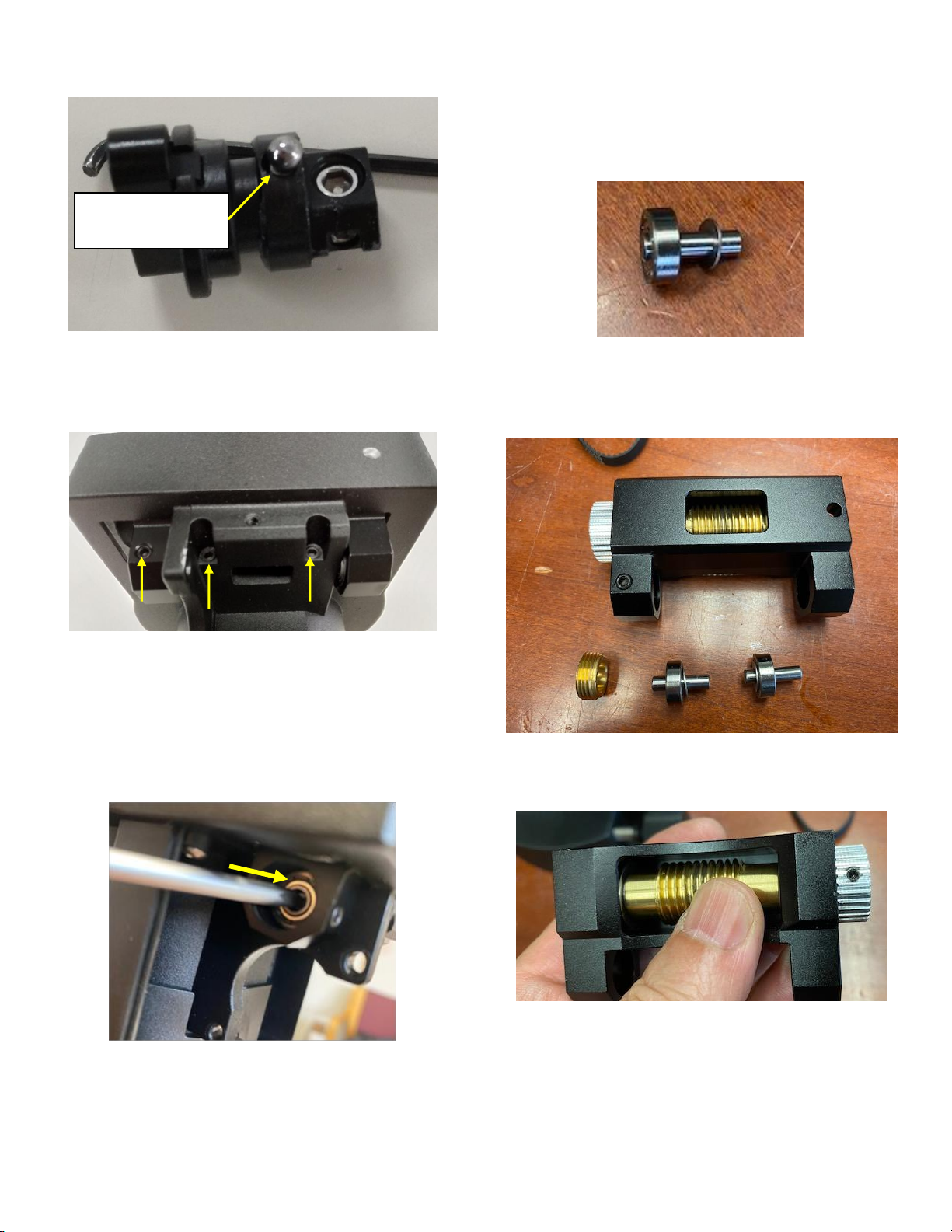
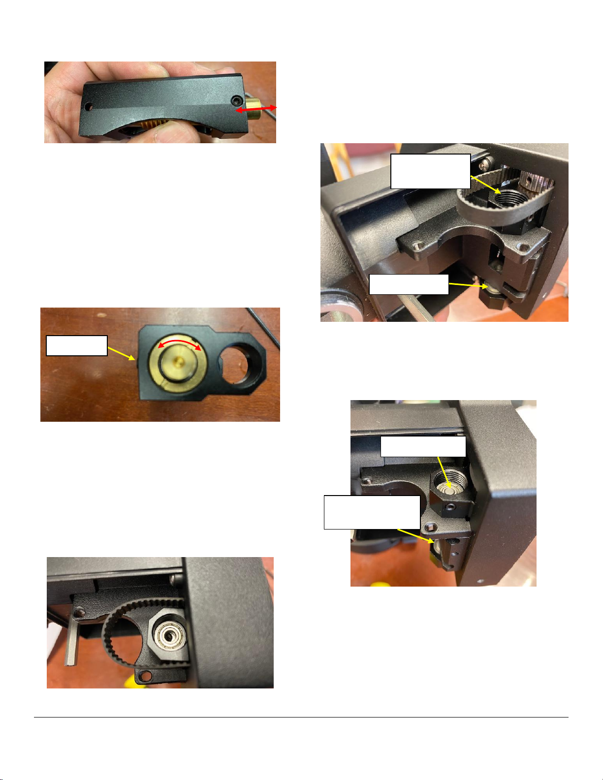
21. Release worm end cap set screw a little.
Tighten the brass end cap by using a pair of
nose pliers or a pair of strong tweezers. Back
out the end cap 1/16-1/8 turn. Turn the worm
shaft with fingers. There should be no stiffness.
Check if the lateral free movement is eliminated.
Tighten the set screw. Check the worm
smoothness again. If there is any stiffness
exists, you need to readjust the worm end cap.
Until there is no lateral play, or worm stiffness.
22. Put the worm pulley back on to the worm shaft.
Locate the flat surface on the shaft and tighten
the set screw onto it. Make sure that the worm
shaft end if aligned flash to the pulley surface.
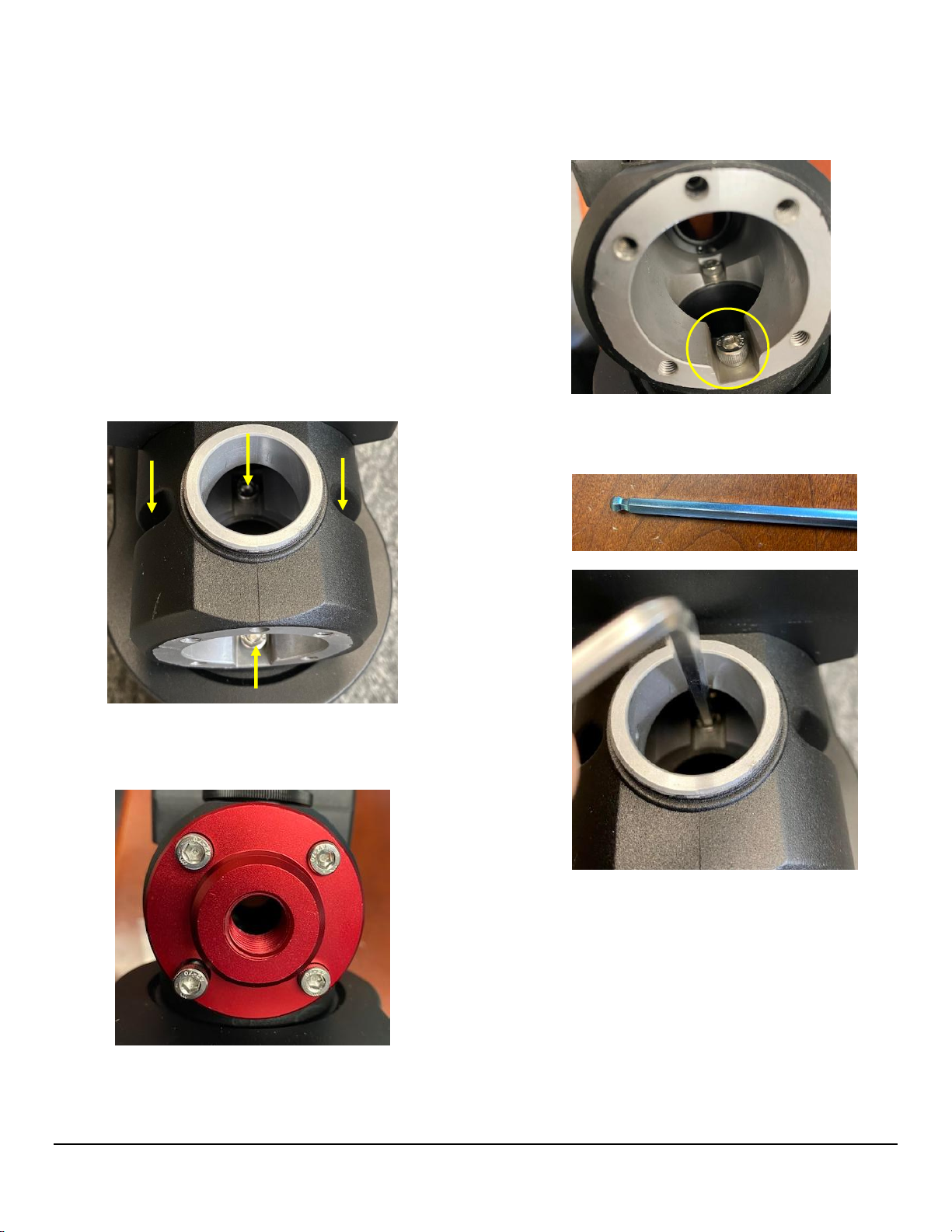
23. Before install the worm assembly, insert one
hinge bearing into the bearing housing without
the locking end cap.
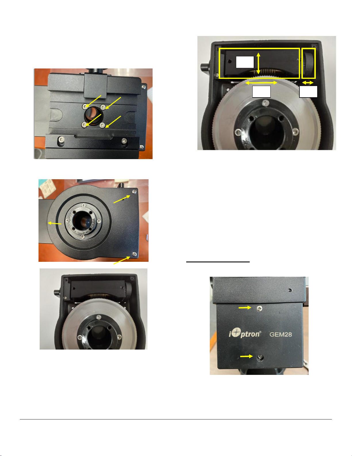
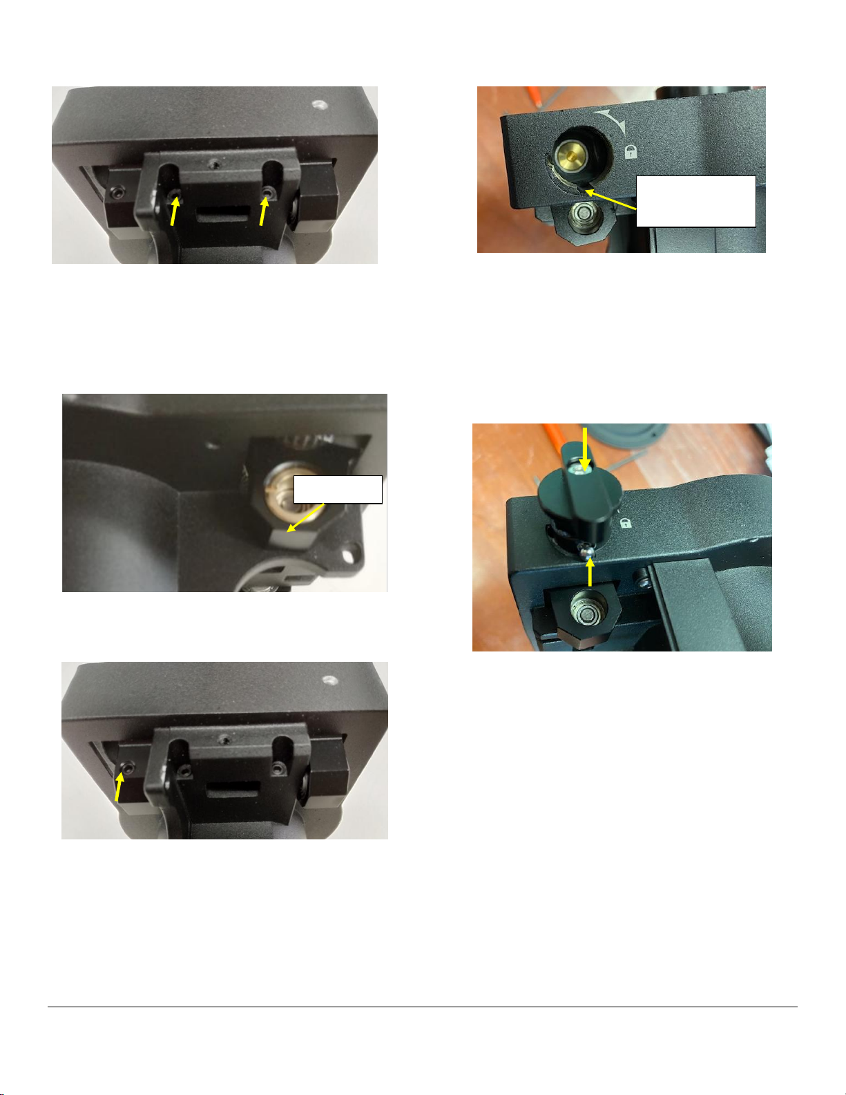
24. Wrap the belt over the worm pulley and insert
the worm assembly back into the ring gear
compartment. You may rotate the mount head
90 degree so the worm pulley and open-ended
hinge pin bearing house is on top.
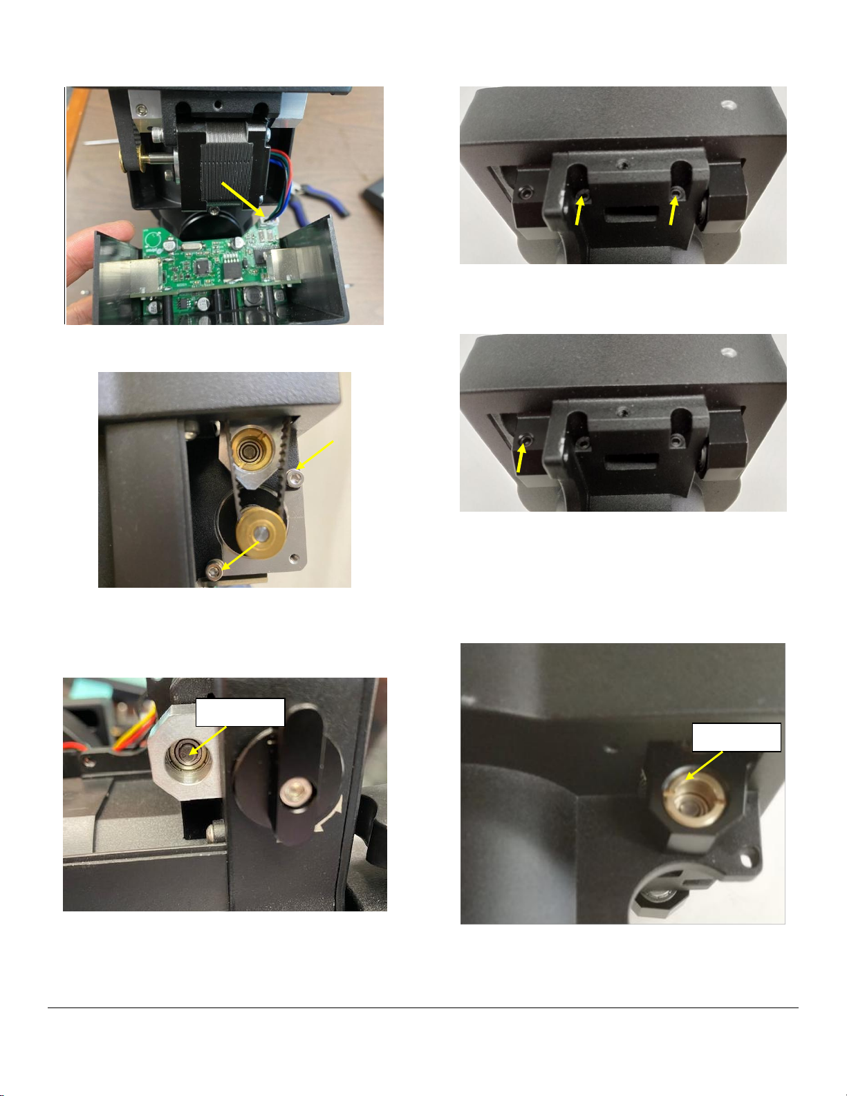
25. Insert hinge pins while insert the washer
between the bearing and worm assembly body.
Tap the hinge pin inward to make sure its end
flash with the bearing surface.
26. Lock hinge pin by tightening the locking set
screws.
Hinge bearing
Hinge bearing
and end cap
Set screw
Washer goes next
to bearing
Hinge pin end
For iOptron Internal Use Only
8
27. Turn the brass end cap clockwise all the way in
using a pair of strong tweezers or a screw
driver. Then un-tighten the end cap 1/16-1/8
turn. Check the worm assembly that it can
moved freely and no free play.
28. Tighten the hinge end cap set screw. Check the
play again.
29. Now install the gear switch back.
30. Insert the spring into the gear switch hole. Put
the ball bearing on top of it. Insert gear switch
into the worm assembly while align the ball
bearing to the slot. Push ball into the switch
body while push the gear switch into the worm
assembly. Need be very careful not to spring
away the ball and spring.
31. Turn the gear switch while push it inward to
check if it is smooth. Then insert the gear
switch locking pin and secure it.
End cap
Ball bearing
goes in this slot
For iOptron Internal Use Only
9
32. Check the play with worm/ring gear engaged
while rotating the ring gear.
33. Follow steps 10-12 to put the motor, control
board and cover back.

Other manuals for GEM28

2

Other iOptron Industrial Equipment manuals

iOptron iPolar User manual

iOptron

iOptron iPolar User manual

iOptron iEAF 8453 User manual

iOptron

iOptron iEAF 8453 User manual

iOptron CEM70 User manual

iOptron

iOptron CEM70 User manual

Popular Industrial Equipment manuals by other brands

Siemens 3WN6 operating instructions

Siemens

Siemens 3WN6 operating instructions

Afag BF25 Translation of operating and installation instructions

Afag

Afag BF25 Translation of operating and installation instructions

Danfoss Optyma Slim Pack instructions

Danfoss

Danfoss Optyma Slim Pack instructions

McElroy Hornet XL Series Operator's manual

McElroy

McElroy Hornet XL Series Operator's manual

Wachs SDB 206 user manual

Wachs

Wachs SDB 206 user manual

Schulte FM-350 Operator's manual

Schulte

Schulte FM-350 Operator's manual

SY-KLONE POWERED PRECLEANER XLR Service & Installation

SY-KLONE

SY-KLONE POWERED PRECLEANER XLR Service & Installation

Phuel 145-2884-HV0 user manual

Phuel

Phuel 145-2884-HV0 user manual

FLENDER B H 23 28 Series Assembly and operating instructions

FLENDER

FLENDER B H 23 28 Series Assembly and operating instructions

eta ETAbox user manual

eta

eta ETAbox user manual

Phoenix Mecano Dewert Okin DUOMAT 9 installation instructions

Phoenix Mecano

Phoenix Mecano Dewert Okin DUOMAT 9 installation instructions

pela tools 50845 quick start guide

pela tools

pela tools 50845 quick start guide

Challenge CMT 330 Installation and operator's manual

Challenge

Challenge CMT 330 Installation and operator's manual

Loctite Zeta 7215 Operation manual

Loctite

Loctite Zeta 7215 Operation manual

Buhler GAS 222.10 Assembly, installation and operation instructions

Buhler

Buhler GAS 222.10 Assembly, installation and operation instructions

ABB HT562399 Operation manual

ABB

ABB HT562399 Operation manual

ABB HT573736 Operation manual

ABB

ABB HT573736 Operation manual

AIC PS user manual

AIC

AIC PS user manual

manuals.online logo
manuals.online logoBrands
  • About & Mission
  • Contact us
  • Privacy Policy
  • Terms and Conditions

Copyright 2025 Manuals.Online. All Rights Reserved.