IOTAVX ILB-CP-HE-SD User manual

IMPORTANT SAFEGUARDS
When using electrical equipment, basic safety precautions should always be followed, including the following:
READ AND FOLLOW ALL SAFETY INSTRUCTIONS
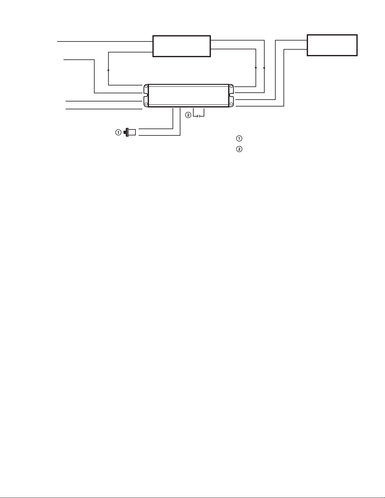
1. CAUTION – To prevent electrical shock, do not mate unit connector until installation is complete and A.C.
power is supplied to the unit.
2. CAUTION – This fixture provides more than one power supply output source. To reduce the risk of electrical
shock, disconnect both normal and emergency sources by turning off the A.C. branch circuit and by discon-
necting the unit connector.
3. CAUTION – This is a sealed unit. Components are not replaceable. Replace the entire unit when necessary.
4. CAUTION – Installation and servicing should be performed by qualified personnel only. De-energize before
opening.
5. The ILB-CP-HE-SD is for use with grounded LED luminaires listed to UL standards. Not for use in heated air
outlets or hazardous locations.
6. The ILB-CP-HE-SD requires an unswitched A.C. power source of 120 to 277 volts AC, 50/60Hz.
7. The ILB-CP-HE-SD and A.C. driver must be on the same branch circuit.
8. Do not mount near gas or electric heaters.
9. The ILB-CP-HE-SD should be mounted in locations and at heights where it will not readily be subjected to
tampering by unauthorized personnel.
10. The ILB-CP-HE-SD will supply 10-60VDC output at the individual rated specification for 90 minutes. See indi-
vidual units for output specifications.
11. The ILB-CP-HE-SD is certified in the CA Title 20 Modernized Appliance Efficiency Database System (MAED-
BS) as a small battery charger.
12. Suitable for installation in or on top of compartment spaces. Flexible conduit not needed for internal compart-
ment installation. For top mounting, use the TMK-80 accessory.
13. Suitable for use in damp locations and enclosed and gasketed fixtures.
14. Suitable for luminaires, recessed Type IC (intended for insulation contact).
15. For use in 0° C minimum, 55° C maximum ambient temperatures.
16. The use of accessory equipment not recommended by the manufacturer may cause an unsafe condition, void
warranty, and result in non-compliance with UL specifications.
17. Do not use this equipment for other than intended use.
18. Install in accordance with the National Electrical Code and local regulations.
19. Lighting fixture manufacturers, electricians, and end-users need to ensure product system compatibility before
final installation. See addendum for compatibility and covered luminaire requirements.
SAVE THESE INSTRUCTIONS
ILB-CP-HE-SD
‘B’ MOUNTING DESIGN
HIGH EFFICIENCY EMERGENCY
LIGHTING EQUIPMENT
FOR LED
INSTRUCTION MANUAL
P.O. BOX 11846 TUCSON, AZ 85734
(520) 294-3292 • FAX (520) 741-2837
www.iotaengineering.com Patented. See iotaengineering.com/patents for more details
HIGH EFFICIENCY PERFORMANCE
MEETS CA T20 BATTERY CHARGER
EFFICIENCY STANDARDS
EMERGENCY LED DRIVER FOR USE
WITH LED LUMINAIRES IDENTIFIED
IN THE MANUFACTURER’S
INSTALLATION INSTRUCTIONS
E473237

Page 2
3. WIRING
Refer to the Illustration 3 for the appropriate wiring of the LED load and driver. Install in
accordance with the National Electrical Code and local regulations. For additional wiring diagrams consult
Customer Service.
4. INSTALLING THE THREADED BODY TEST SWITCH (TBTS)
Select a convenient location on the side of the fixture so that the TBTS can be seen after installation. Allow for
proper clearance and drill or punch a ½″hole. Remove the nut from the TBTS. Push the TBTS housing into the
½″hole and secure with the nut. Connect the LED wires from the unit to the TBTS (Red/Black to Red, and White/
Red to White). For proper operation, use only the accessory components provided with the unit. See Page 1 of the
Instruction Manual.
INSTALLATION INSTRUCTIONS
CAUTION: Before installing, make certain the A.C. power is off and the ILB-CP-HE-
SD unit connector is disconnected.
1. FIXTURE
The ILB-CP-HE-SD can be used with most LED loads that operate at 10-60 VDC. See the ILB Model
Specification Chart for output specifications of the unit being installed.
1. The ILB-CP-HE-SD series has been evaluated to and found compliant to UL standard 924. The as-installed
performance of system must meet or exceed all Federal, State, and Local code requirements.
2. Refer to Addendum 11042014 for detailed specifications and methods to calculate emergency light levels.
2. MOUNTING THE ILB-CP-HE
Mount the ILB-CP-HE-SD in the driver/lamp compartment or enclosed wireway so the wire leads are not exposed,
at least ½″
away from the driver. Refer to Illustration 1.
For mounting the ILB-CP-HE-SD on top of the fixture, use the optional TMK-80 mounting accessory for covering
the wires that enter the fixture. Refer to Illustration 2.
When battery packs are remote mounted, the maximum distance between the unit and the LED Load must not
exceed 50 ft.
Illustration 1
ILB-CP10-HE-SD 10 WATTS
ILB MODEL SPECIFICATION CHART
OUTPUT POWER (CONSTANT)
NOTE: Position the TBTS so that
it can be seen after installation.
7/8”
BUSHING
DRIVER
COMPARTMENT
TBTS
CEILING
TILE
7/8” BUSHING
DRIVER
COMPAR
TMENT
TBTS
CEILING
TILE
TMK-80
Illustration 2
ILB-CP-HE-SDILB-CP-HE-SD

Page 3
ILB-CP-HE-SD WITH TBTS TEST ACCESSORY
ILBCP_TBTS_SD.EPS
AC (NORMAL)
DRIVER
IOTA ILB-CP-HE-SD
EMERGENCY DRIVER
LED
LOAD
WHITE
WHITE
BLACK
BLK/WHT
COMMON
UNSWITCHED
24/7 POWER BLK/ORG (120 TO 277V, 50/60HZ)
AC INPUT (120 TO 277V)
SWITCHED OR
UNSWITCHED
HOT
TBTS
TEST ACCESSORY
RED (+)
BLUE (-)
RED/WHT (+)
BLUE/WHT (-)
LED INPUT(+)
LED INPUT (-)
LED OUTPUT (+)
LED OUTPUT (-)
UNIT
CONNECTOR
WHT/RED
RED/BLK (+)
ATTENTION: DO NOT MATE UNIT CONNECTOR UNTIL
INSTALLATION IS COMPLETE AND AC POWER IS SUPPLIED.
TEST ACCESSORY LEADS-OBSERVE PROPER
POLARITY WIRING.
MATE UNIT CONNECTOR AFTER INSTALLATION IS
COMPLETE AND AC POWER IS SUPPLIED
Illustration 3: Typical Wiring Diagram
5. LABELS
Attach the appropriate labels adjacent to the TBTS. Annotate Replacement Label with identical manufacturer part
number(s). The Caution and the Replacement labels must be on the fixture in a readily visible location to anyone
attempting to service the fixture.
6. WIRING THE A.C. INPUT
A. The ILB-CP-HE-SD and A.C. driver MUST be on the same branch circuit.
B. The ILB-CP-HE-SD requires an unswitched A.C. power source of 120 to 277 VAC, 50/60Hz; therefore when
used with switched fixtures, the ILB input must be wired ahead of the switch.
C. Refer to the wiring diagram for proper wiring. For wiring diagrams not shown, consult our customer service.
7. COMPLETING INSTALLATION
When the installation is complete, switch the A.C. power on and join the ILB-CP-HE-SD unit connector. NOTE: If
the battery has been fully discharged, the TBTS indicator may remain OFF for a few minutes until the battery has
achieved sufficient charge for functional testing.
OPERATION
Normal Mode – A.C. power is present. The A.C. driver operates the LED load as intended. The ILB-CP-HE-SD is in the
standby charging mode. The TBTS will be flashing green providing a visual indication that the battery is being charged,
or solid green if the battery is fully charged.
Emergency Mode – The A.C. power fails. The ILB-CP-HE-SD senses the A.C. power failure and automatically switches
to the Emergency Mode. The designated LED arrays are illuminated, for a minimum of 90 minutes. When the A.C.
power is restored, the ILB-CP-HE-SD switches the system back to the Normal Mode and resumes battery charging.
See page 1 of the Instruction Manual.
TESTING & MAINTENANCE
The ILB-CP-HE-SD is designed to automatically conduct 30-second tests at regular intervals every 28 to 30 days, and
a 90 minute test anually. Automatic testing will not begin until at least 24 hours after the ILB-CP-HE-SD unit connector
is joined.
Load Calibration - 48 hours after the unit connector is joined, the ILB-CP-HE-SD will conduct a Load Calibration.
Note: after the Load Calibration is complete, any changes to the LED load that will affect its nominal input voltage will
necessitate a new Load Calibration (see table below for the sequence of button presses to conduct a manual Load
Calibration). Automatic Testing will proceed in the following schedule:

Page 4
68D10-117
REV 1901
Automatic Monthly Testing – The ILB-CP-HE-SD will automatically conduct a 30 second test once every month. If the
ILB-CP-HE-SD encounters a problem, the TBTS will flash RED. See the Table A below for diagnosis.
Automatic Annual Testing – The ILB-CP-HE-SD will automatically conduct a 90 minute test every twelve months.
If the ILB-CP-HE-SD encounters a problem, the TBTS will flash RED. See the Table A below for diagnosis.
To insure accurate testing, the ILB-CP-HE-SD will not conduct any scheduled automatic tests or allow for manual
testing or calibration for a period of up to 24 hours after the unit has discharged, regardless of reason. This period is
easily indicated by the TBTS flashing green.
Failure Diagnosis - The ILB-CP-HE-SD is designed to provide a general indication of where a fault in the emergency
lighting circuit may be located, based on the flashing failure code indicated by the TBTS.
Charge Failure - A fault is preventing the ILB-CP-HE-SD from charging correctly. Please contact Customer
Service.
Battery Failure - The ILB-CP-HE-SD battery is unable to fully charge, or was not able to supply sufficient
voltage to the LED load during a test. Please contact Customer Service.
Load Failure - The ILB-CP-HE-SD has detected an issue with your LED load or the ILB-CP-HE-SD internal
load transfer. If it can be verified that the LED load is operating correctly, please contact Customer Service.
Note: in cases of multiple failures only the highest priority failure will be indicated. Charge Failure is the highest priority
failure, followed by Battery Failure, followed by Load Failure.
LED IS FLASHING GREEN WHEN CHARGING, SOLID GREEN WHEN READY. FAILURE CODES ARE
INDICATED BY THE RED LED
CHARGE FAILURE
BATTERY FAILURE
LOAD FAILURE
1 FLASH
2 FLASHES
3 FLASHES
FAILURE CODES OCCUR ONCE EVERY
15 SECONDS. ONLY HIGHEST PRIORITY
FAILURE IS INDICATED.
For more information on diagnosing ILB-CP-HE-SD failure codes, contact Customer Service.
Manual Testing - Manual Testing can be performed on the ILB-CP-HE-SD, provided the unit is fully charged, by press-
ing and releasing the TBTS or engaging the wall switch that controls the emergency luminaire. Manual Testing cannot
be initiated until the unit has received a full 24 hour charge. Manual Testing will not interfere with the automatic testing
schedule of the ILB-CP-HE-SD and will display the same diagnosis indicators as automatic testing. Activate the desired
test using the sequences in Table B below:
SERVICING SHOULD BE PERFORMED BY QUALIFIED PERSONNEL.
Consult Customer Service or visit www.iotaengineering.com for current warranty information.
Table A:TBTS Self-Diagnostic codes
CANCEL 90-MINUTE TEST
30-SECOND TEST
90-MINUTE TEST
1 X PRESS AND RELEASE
PRESS AND HOLD
2 X PRESS AND RELEASE
A LOAD CALIBRATION CAN ALSO BE PERFORMED BY DISCONNECTING AND RECONNECTING THE UNIT CONNECTOR
ILB-CP-HE-SD MANUAL TESTING SEQUENCES
LOAD CALIBRATION
1
1
TOGGLE = SWITCHING TO ON STATE OR OFF STAT E
2
WALL SWITCH TESTING IS NOT RECCOMMENDED FOR PHASE-DIMMING APPLICATIONS
3
UNIT CONNECTOR MUST BE CONNECTED
4
2
3
4
QUICK TEST
3 X PRESS AND RELEASE
4 X PRESS AND RELEASE
TBTSTEST TYPE WALL SWITCH MINIMUM BATTERY CHARGE REQUIREMENTS
N/A
6 TOGGLES
8 TOGGLES
4 TOGGLES
N/A
2 HOURS
24 HOURS
24 HOURS
24 HOURS
ILB-CP-HE-SD MANUAL TESTING SEQUENCES - CANCELLING TEST
TBTSTEST TYPE WALL SWITCH MINIMUM BATTERY CHARGE REQUIREMENTS
UNIT MUST BE IN SELF-TEST MODE
Table B: Manual Test Sequences
Table C: Cancel a Test

Addendum Insert
CP Series Compatibility and Suitability of Use Guidelines
Addendum (Rev.11042014)
The purpose of this addendum is to sufficiently identify electrical compatibility and predictable emergency light output of
the LED luminaire when used with the IOTA ILB-CP Series LED emergency drivers. Verification of these operating traits
does not constitute a code-compliant, as-installed emergency egress system. It is still the responsibility of the Designer/
Specifier to assure appropriate light levels are achieved during emergency operation of the luminaire in accordance
with Federal, state and local municipal codes regarding path of egress illumination.
1. Determining Electrical Compatibility
1.1 Verify Class 2 compliant driver per driver manufacture specifications.
1.2 Verify that the Emergency Driver (ILB-CP Series) selected does not exceed the power delivered to the LED
array (voltage and current) of the normal driver.
2. Calculating Lumen Output During Emergency Operation
2.1 Assess luminaire/fixture data.
2.1.1 DESIGNLIGHTS CONSORTIUM
- Log onto the DesignLights Consortium website (www.designlights.org).
- Click on “search the DLC Qualified Product List” button on the DLC homepage.
- In the “search by keyword” text window enter: luminaire manufacturer name and part number.
- Click on “Search” tab to open the “Qualified Products List.”
- Determine per “RATED DATA” efficacy shown in lumens per watt - (lm/w).
- Multiply lumens per watt by ILB-CP rated output (example: lm/w x 5 watts). Refer to table “ILB
MODEL SPECIFICATION CHART” below for the wattage of the specific ILB-CP model to be
used in the luminaire. (lm/w) x (ILB-CP Watts) = Minimum emergency lumens of fixture.
- Determine per “RATED DATA” the “wattage of the luminaire”.
3. Determining Adequacy of Means-of-Egress Lighting Levels
3.1 Follow industry standards by utilizing available .ies files and lighting design software for your dedicated
emergency luminaires, with the above calculated emergency lumens, and validate your as-installed
plans in accordance with the applicable life safety codes governing your project.
While the ILB-CP series has been found compliant with the requirements of UL Standard 924, it is
ultimately the responsibility of the Designer/Specifier to assure the as-installed system delivers code-
compliant path of egress illumination in accordance with Federal, State or local municipal requirements.
ILB-CP05
ILB-CP07
ILB-CP10
5 WATTS
7 WATTS
10 WATTS
ILB MODEL SPECIFICATION CHART
OUTPUT POWER (CONSTANT)
ILB-CP12 12 WATTS
ILB-SL-CP05
ILB-SL-CP07
ILB-SL-CP10
5 WATTS
7 WATTS
10 WATTS
ILB-SL-CP12 12 WATTS
ILB-CP20 20 WATTS
ILB-SL-CP08 8 WATTS
68D10-117
REV 1901
This manual suits for next models
10
Table of contents
Popular Lighting Equipment manuals by other brands

ADJ
ADJ SUPER SPOT LED User instructions

Federal Signal Corporation
Federal Signal Corporation IMPAXX installation instructions

Colors
Colors CR4-GBA quick start guide

UFO
UFO Vega Product user guide

SCHOTT
SCHOTT LLS 3 user manual

American Lighting
American Lighting Hybrid 3 120-H3 Series installation instructions