iPark IPTSWR400 User manual

IPTSWR400
WIRELESS PAR ING ASSIST SYSTEM MANUAL
iPark_IPTSWR400_Manual_Layou 1 10/30/14 9:27 AM Page 1

TABLE OF CONTENTS
1 Important Notice - Disclaimer - About The Product
2 ey Features - Technical Specifications
3 Self-Test Function - Attention – Sensor Maintenance
4 Audible Buzzer Function
5 Packing List - Installation Tools
6,7 Sensor Installation
8 Wiring Diagram
9 ECU Installation
10 Troubleshooting
11 Function Test After Installation
12 Voice Settings - Display Button Functions
13 Volume Settings - Volume Reset Function
iPark_IPTSWR400_Manual_Layou 1 10/30/14 1:15 PM Page 2

page 1
IMPORTANT NOTICE
iPAR ® Parking Assist Systems help to
provide assistance when reversing and
parking.
Driving skills, such as using caution,
slowing down, use of mirrors etc. are
always essential.
1. This unit is for use with 12V DC only.
2. Unit should be installed by a
professional auto technician to avoid the
warranty being voided.
3. Route wiring harness away from heat
sources and electrical components.
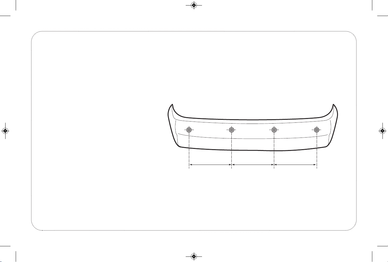
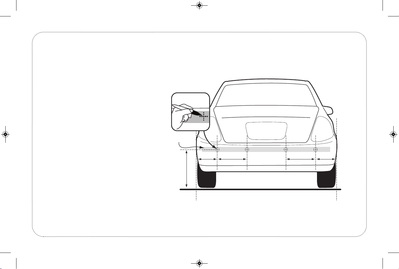
4. It is strongly recommended to check
behind the planned location of the
sensors before drilling.
5. Perform a test after installation is
complete.
DISCLAIMER
The parking assist system is designed as
a driver assistance device, and should not
be used as a substitute for safe parking
practices. The area into which the vehicle
is to be reversed must be constantly visu-
ally monitored while parking. The manu-
facturer, its distributors and sales agents,
do not guarantee against or assume
liability for collisions or damages while
reversing your vehicle.
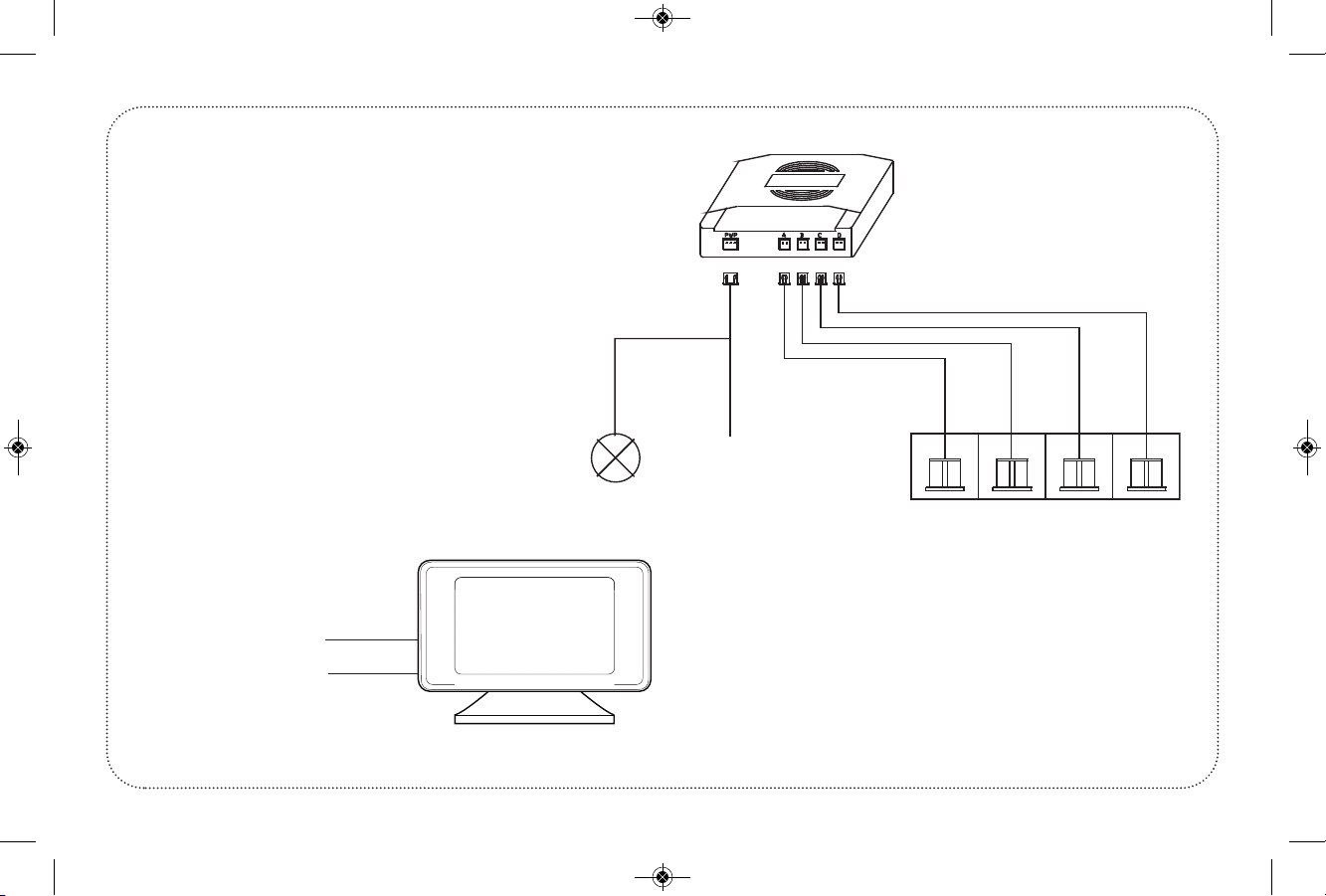
ABOUT THE PRODUCT
This Parking Assist System is an
ultrasonic detection and distance
monitoring system.
It electronically detects the area behind
your vehicle while reversing, and alerts
you with audible tones that quicken and
eventually become a constant tone, if the
system detects an obstacle. If the system
has the optional display, it will show the
distance in FEET, numerically. This is, as
well as, audible tones and progressive
LEDs.
Each part of this product has passed a
stringent test during manufacturing. The
product is designed to operate at a wide
range of temperatures from -40ºF to
+175ºF and becomes very useful when
parking during poor weather conditions.
With the help of a Parking Assist System,
you can enjoy a comfortable and conven-
ient parking experience.
iPark_IPTSWR400_Manual_Layou 1 10/30/14 9:27 AM Page 1

KEY FEATURES
• Display does not connect to the rear module (ECU) it communicates
wirelessly, with built-in audible
• BEEP tones and visual display options
• System can be used on both metal bumpers and plastic bumper covers
• Precise detection range
• Self-Test and Auto Anti-Falsing Alert technology
TECHNICAL SPECIFICATIONS
• Rated Voltage: . . . . . . . . . .12V DC
• Power Consumption: . . . .3.6W
• Working Temperature: . .-20ºC to +70ºC
• Detecting Distance: . . . . .1ft to 6.5ft
• Detecting Angle: . . . . . . .H>60º, V>60º
page 2
iPark_IPTSWR400_Manual_Layou 1 10/30/14 9:27 AM Page 2

SELF TEST FUNCTION
When reverse gear is selected, the sys-
tem will test the rear sensors
automatically.
If all sensors are working correctly, the
unit will beep once.
If a damaged or defective sensor is
detected the unit will beep three times.
Other sensors will continue to function
normally.
ATTENTION
False detection may occur in the
following situations.
• Angled or sloped walls or objects may
deflect the ultrasonic signal.
• Soft fabrics, carpeting or padded sur-
faces may absorb the ultrasound and
not give an accurate reading.
• Buildings with staggered walls or
insets may also absorb or deflect the
signal.
• Heavy Rain, dirty or damaged sensors
may also cause false warnings.
SENSOR MAINTENANCE
Do not wash the sensors with a
pressure washer or scrub them forcibly.
Avoid wax or grim buildup in the
sensors. Wash the sensors with water in
a low pressure manner.
Please allow the ice to melt by
applying water when sensors are
covered with frozen ice.
page 3
iPark_IPTSWR400_Manual_Layou 1 10/30/14 9:27 AM Page 3

AUDIBLE BUZZER FUNCTION
6.5FT to 4FT – Slow BEEP—BEEP—BEEP
4FT to 2FT – Faster BEEP BEEP
2FT to 0FT – Constant BEEEEEEP
Unit will also have VOICE alerts for distance in FEET
On-Screen display of object location and distance in FEET
page 4
SENSOR STATUS
VOICE STATUS
• Siren Icon Crossed: The unit beeps (no voice alert)
• Siren Icon/Not crossed: The unit has both
beep and voice alert
DISTANCE DISPLAY
MATRIX POSITIONING
iPark_IPTSWR400_Manual_Layou 1 10/30/14 9:27 AM Page 4

PACKING LIST
4 Sensors (Metal Bumper) 1 Control ECU Module
4 Sensor Extension Cables 1 Audible BUZZER
1 Power Harness 1 Hole Saw
1 Square Two-Faced Mounting Tape 1 Manual
INSTALLATION TOOLS
Power Drill Tape Measure
Electrical Tape Scissors
Soldering Iron / Solder Hole File
Screw Driver Skill nife
(Approximately 30 to 60 Minutes)
page 5
IMPORTANT –The installation m st be completed o tdoors, 10 FEET clearance of any objects or b ildings etc.
iPark_IPTSWR400_Manual_Layou 1 10/30/14 9:27 AM Page 5

SENSOR INSTALLATION
Please adjust the sensors angle to be
parallel to the ground surface
depending on the height and angle of
the mounting surface. Ideal mounting
height is between 18 to 25 inches.
Position the 4 sensors to be equally
spaced apart on the bumper. Best
location is outer two sensors spaced 8 to
10 inches in from outer edge of vehicle.
Measure the distance between the two
sensors, and divide by three to be
location for the other two sensors.
page 6
SENSOR INSTALLATION
WHEN BUMPER IS REMO ED
iPark_IPTSWR400_Manual_Layou 1 10/30/14 9:27 AM Page 6

A
C
BBA
TAPE
SENSOR INSTALLATION (Continued)
DIRECT ON EHICLE BUMPER
page 7
iPark_IPTSWR400_Manual_Layou 1 10/30/14 9:27 AM Page 7

MAIN BOX
RED (+)12V
BLACK (-) GND
SENSOR A
4 SENSORS - INSTALL ON REAR BUMPERS
SENSOR B
SENSOR C
SENSOR D
REVERSE
LIGHT
WIRING DIAGRAM
Reverse Light (+)12V DC Red
Black (-) Ground
Sensors ABCD
Wiring Diagram for 4 Sensor Rear System
page 8
DISPLAY
Ignition - (+)12V DC Red
Chassis - (-) Gnd Black
iPark_IPTSWR400_Manual_Layou 1 10/30/14 9:27 AM Page 8

Pull
Back
+12V
Lens Cover
Module
ECU INSTALLATION
Reverse Light (+) 12V Red
Ground (-) Black
page 9
iPark_IPTSWR400_Manual_Layou 1 10/30/14 9:27 AM Page 9

TROUBLESHOOTING
Parking sensor system does not work after installation
Trouble . . . . . . . . . . . . . . . . . . . . . . . . . . . . . . . . . . . . .Solution
A) Power wire is connected incorrectly . . . . . . . . . . . . . . . . . . . . . . . . . . . . .Recheck (+) wiring
B) Power Harness is not inserted in ECU module . . . . . . . . . . . . . . . . . . . .Unplug and check
C) Vehicle is not correctly in Reverse . . . . . . . . . . . . . . . . . . . . . . . . . . . . . . . .Check Gear is in R (damaged sensor is detected)
Damaged sensor is detected
Trouble . . . . . . . . . . . . . . . . . . . . . . . . . . . . . . . . . . . . .Solution
A) Are all sensors connected correctly and tightly? . . . . . . . . . . . . . . . . . .Reconnect each sensor
B) Is there a faulty defective sensor? . . . . . . . . . . . . . . . . . . . . . . . . . . . . . . . .Replace defective sensor
C) Is the sensor covered by dirt or is dirt inside sensor assembly? . . .Clean sensor to clear (false warning or range too short)
False warning or range to short
Trouble . . . . . . . . . . . . . . . . . . . . . . . . . . . . . . . . . . . . .Solution
A) Sensors are angled down “seeing” ground surface . . . . . . . . . . . . . . . .Adjust with angle ring
B) Sensor has packing material or dirt in assembly . . . . . . . . . . . . . . . . . .Disassemble, Clear sensor
C) Hole in Bumper Cover has plastic buildup in the back . . . . . . . . . . . .Clean back of bumper cover of plastic burr (which is
. . . . . . . . . . . . . . . . . . . . . . . . . . . . . . . . . . . . . . . . . . . . . . . . . . . . . . . . . . . . . . . . . .restricting sensor from functioning correctly)
Warning sound too loud
Trouble . . . . . . . . . . . . . . . . . . . . . . . . . . . . . . . . . . . . .Solution
A) Switch on Buzzer is set to HI position . . . . . . . . . . . . . . . . . . . . . . . . . . . .Set switch to LO
B) Buzzer is too close to driver . . . . . . . . . . . . . . . . . . . . . . . . . . . . . . . . . . . . . .Reposition under dash
If any problems persist, please contact yo r local dealer or nearby service center
page 10
iPark_IPTSWR400_Manual_Layou 1 10/30/14 9:27 AM Page 10

6 ft
FUNCTION TEST (AFTER
INSTALLATION)
Function test is performed by holding a
wooden board (12” x 36”), upright
behind the vehicle and slowly backing
the car to test each of the sensors are
functioning correctly.
page 11
iPark_IPTSWR400_Manual_Layou 1 10/30/14 9:27 AM Page 11

OICE SETTINGS
Press the Button
It will add or remove the VOICE from
the alert settings.
If the VOICE function is ON the siren
symbol is clear.
If the VOICE function is OFF the siren
symbol is crossed out.
page 12
DISPLAY BUTTON FUNCTIONS
VOLUME REST DEFAULT IS “7”
PRESS FOR 3 SECONDS
VOLUME (+)
VOLUME (-)
VOICE
FUNCTION
ON/OFF
WITH VOICE WITHOUT VOICE
iPark_IPTSWR400_Manual_Layou 1 10/30/14 9:27 AM Page 12

OLUME SETTINGS
Press ey and the Volume will Decrease from
LOUD to SOFT
Press ey and the Volume will Increase from
SOFT to LOUD
There are a total of 13 steps to the volume level
OLUME RESET FUNCTION
Press and HOLD the ey for 3 Seconds. The
Volume will reset to Level 7
page 13
VOLUME LEVEL ONE VOLUME LEVEL SEVEN
VOLUME LEVEL SEVEN
iPark_IPTSWR400_Manual_Layou 1 10/30/14 9:27 AM Page 13

iPark_IPTSWR400_Manual.qxd 10/14 Rev.1
Warranty
This product is covered by a factory warranty
of 12 months from date of purchase.
In addition this unit is covered by an extend-
ed warranty if installed by an authorized
installation specialist.
Please retain your purchase receipt for proof
of purchase date and warranty coverage.
If you purchased this product through a new
car dealership, you may be entitled to addi-
tional coverage and services according to
your particular state and the auto dealer’s
warranty.
All rights to change or alter designs or specifications are reserved.
iPark_IPTSWR400_Manual_Layou 1 10/30/14 9:27 AM Page 14
Table of contents
Other iPark Automobile Accessories manuals
Popular Automobile Accessories manuals by other brands

Jegs
Jegs 41492 installation instructions

Safe Fleet
Safe Fleet Prime Design FBM-1029 quick start guide

Bestop
Bestop HighRock 4x4 42950 installation instructions

Roadmaster
Roadmaster 155 installation instructions

Cequent Performance Products
Cequent Performance Products CQT76046 installation instructions

Havis-Shields
Havis-Shields KK-K9-D22-K installation instructions

Fortin
Fortin THAR-AUD1 manual

Volvo
Volvo 30661683 Installation instructions, accessories

Scosche
Scosche POWERUP 400 manual

JL Audio
JL Audio Stealthbox SB-J-JL4DDRV/10TW1-2 installation guide

Dobinsons
Dobinsons BU59-3506 installation guide

Metra Electronics
Metra Electronics 95-6549 installation instructions