manuals.online logo
Brands
  1. Home
  2. •
  3. Brands
  4. •
  5. ipf electronic
  6. •
  7. Protection Device
  8. •
  9. ipf electronic OY32 Series User guide

ipf electronic OY32 Series User guide

Other manuals for OY32 Series

2

This manual suits for next models

24

Popular Protection Device manuals by other brands

Merlin Gerin Sepam series 20 Quick start quide

Merlin Gerin

Merlin Gerin Sepam series 20 Quick start quide

OUTSTEEL VENITIAN installation instructions

OUTSTEEL

OUTSTEEL VENITIAN installation instructions

Kemo Electronic M148-24 instructions

Kemo Electronic

Kemo Electronic M148-24 instructions

Endress+Hauser HAW569 quick start guide

Endress+Hauser

Endress+Hauser HAW569 quick start guide

SK ClickClick user manual

SK

SK ClickClick user manual

Ultrasonic SonicPRO installation manual

Ultrasonic

Ultrasonic SonicPRO installation manual

nxt BIA-nXt-DPC 1-22 Installation and operation manual

nxt

nxt BIA-nXt-DPC 1-22 Installation and operation manual

TFortis SG-Switch operating manual

TFortis

TFortis SG-Switch operating manual

BERNINI DESIGN Be172 instruction manual

BERNINI DESIGN

BERNINI DESIGN Be172 instruction manual

Rayleigh Instruments RI-ENERGYSET-3P-ESS-50-100 manual

Rayleigh Instruments

Rayleigh Instruments RI-ENERGYSET-3P-ESS-50-100 manual

E.K.T. ke-DP01 quick start guide

E.K.T.

E.K.T. ke-DP01 quick start guide

Sola HD STV100K Series instruction manual

Sola HD

Sola HD STV100K Series instruction manual

socomec COUNTIS AMd operating instructions

socomec

socomec COUNTIS AMd operating instructions

Siemens SIPROTEC 7SD80 manual

Siemens

Siemens SIPROTEC 7SD80 manual

cias MICRO-RAY installation manual

cias

cias MICRO-RAY installation manual

Sungrow PVS-16MH user manual

Sungrow

Sungrow PVS-16MH user manual

Reer 32010 instruction manual

Reer

Reer 32010 instruction manual

STI STI-7560AC Mounting instructions

STI

STI STI-7560AC Mounting instructions

manuals.online logo
manuals.online logoBrands
  • About & Mission
  • Contact us
  • Privacy Policy
  • Terms and Conditions

Copyright 2025 Manuals.Online. All Rights Reserved.

MANUAL •Subject to alteration! Version: June 2016
ipf electronic gmbh
•Rosmarter Allee 14 •58762 Altena
│
Tel +49 2351 9365-0 •Fax +49 2351 9365-19
│
[email protected] •www.ipf-electronic.com 1
Original Instruction Manual Safety Light Curtain OY32
Devices for finger- and handprotection
Safety Category Type 4
simple installation and configuration
Diagnostics inside
compact profile (32,3x36,9xlength)
Short response time
self testing
Connection with M12-Connector
MANUAL •Subject to alteration! Version: June 2016
ipf electronic gmbh
•Rosmarter Allee 14 •58762 Altena
│
Tel +49 2351 9365-0 •Fax +49 2351 9365-19
│
[email protected] •www.ipf-electronic.com 2
INDEX
1. GENERAL INFORMATION......................................................................................1
1.1. General Description of the safety light curtains ........................................................3
1.1.1. Package contents.....................................................................................................4
1.2. How to choose the device ........................................................................................5
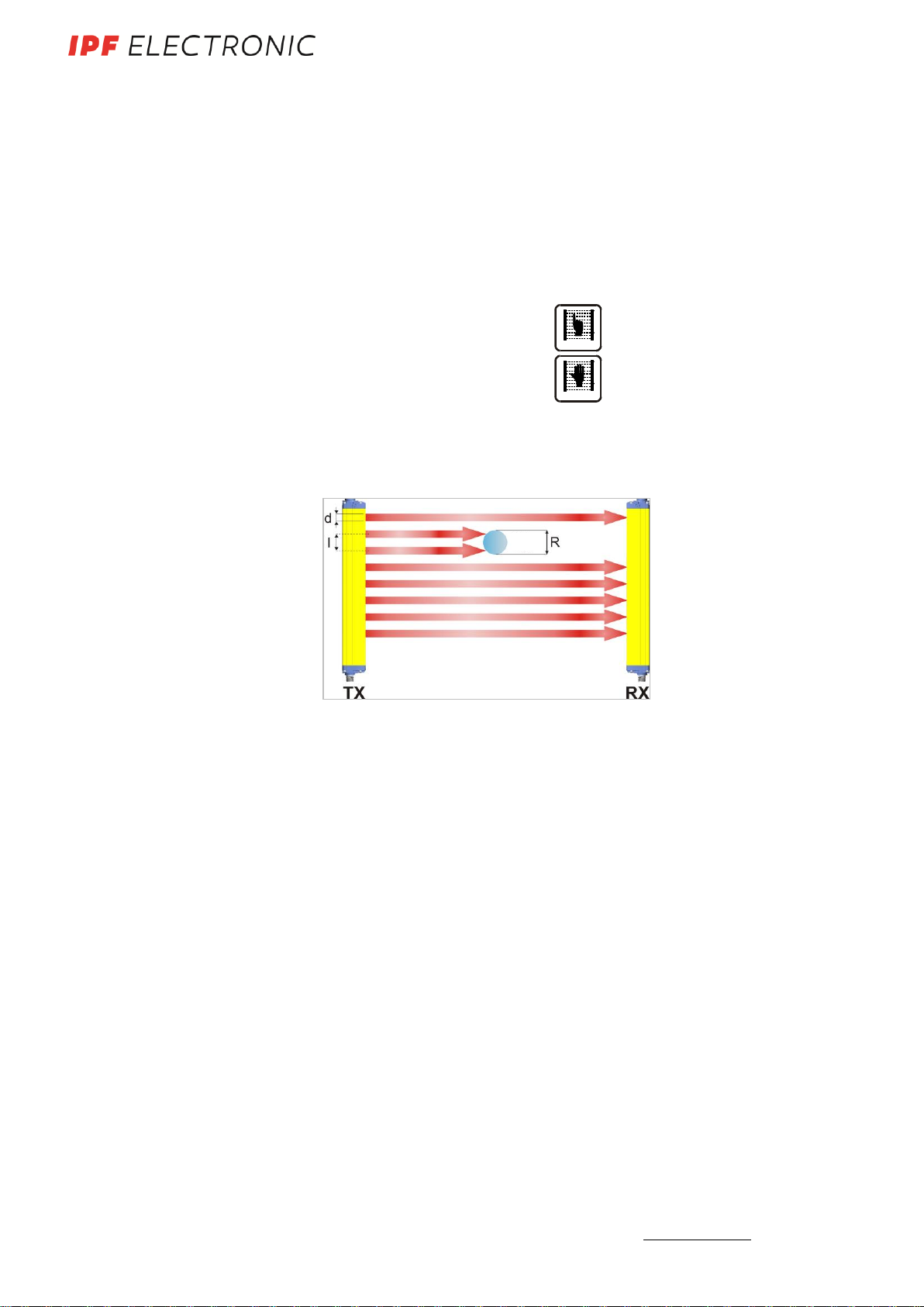
1.2.1. Resolution................................................................................................................5
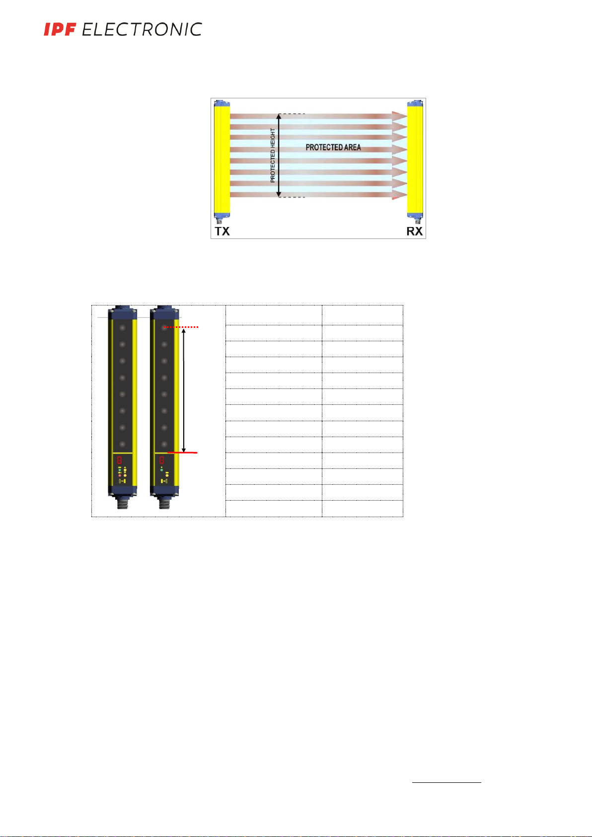
1.2.2. Controlled height......................................................................................................6
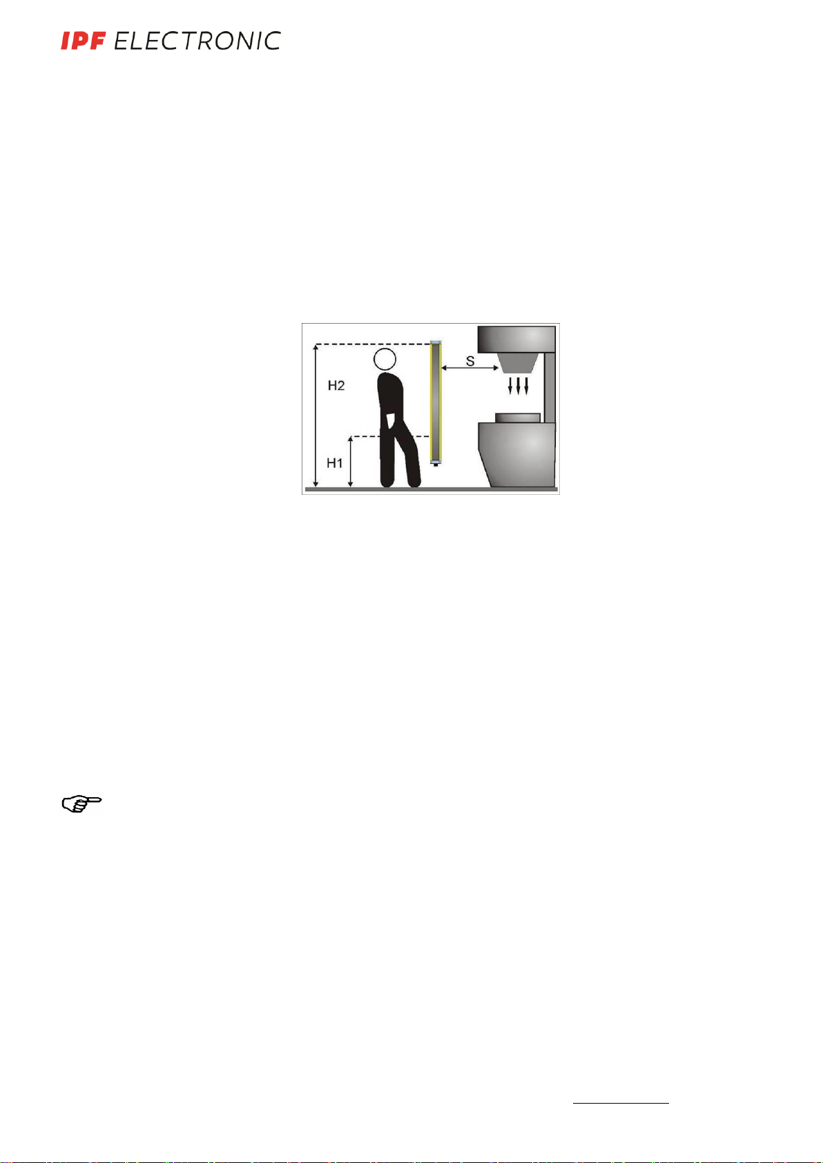
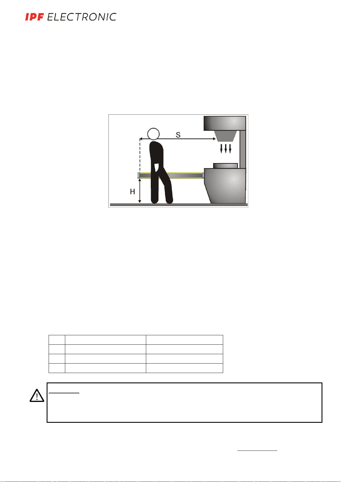
1.2.3. Minimum installation distance...................................................................................7
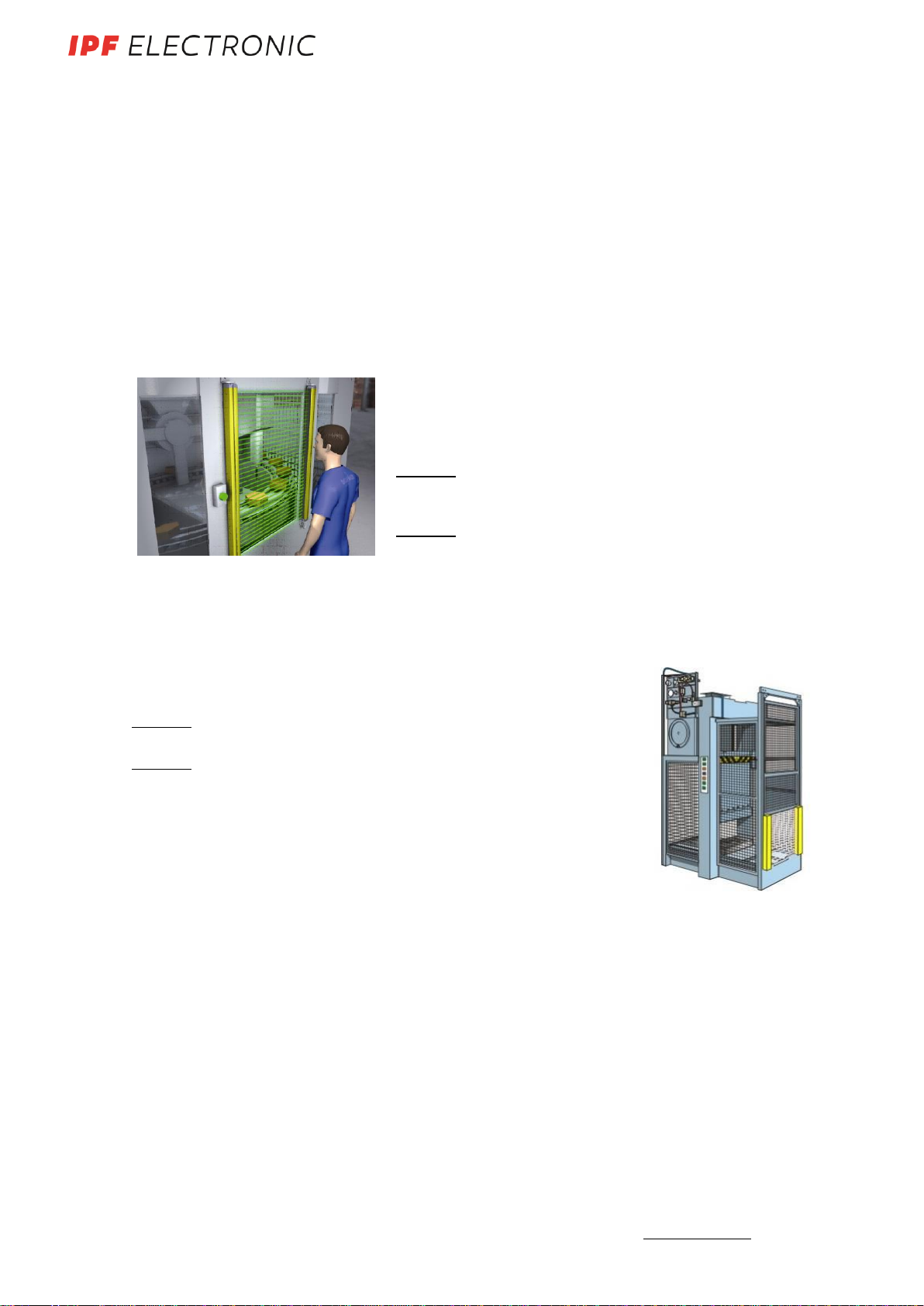
1.3. Typical applications..................................................................................................9
1.4. Serial Number ........................................................................................................11
1.5. Safety information ..................................................................................................11
2. INSTALLATION MODE............................................................................................9
2.1. Precautions to be observed for the choice and installation.......................................9
2.2. General information on device positioning..............................................................10
2.2.1. Minimum installation distance.................................................................................10
2.2.2. Minimum distance form reflecting surfaces ............................................................11
2.2.3. Distance between homologous devices..................................................................13
2.2.4. Emitter and receiver orientation..............................................................................19
2.2.5. Use of deviation mirrors .........................................................................................19
2.2.6. Controls after first installation.................................................................................21
3. MECHANICAL MOUNTING...................................................................................24
4. ELECTRICAL CONNECTIONS..............................................................................24
4.1. Notes on connections.............................................................................................25
4.2. Ground connection.................................................................................................27
5. ALIGNMENT PROCEDURE...................................................................................28
5.1. Correct alignment procedure..................................................................................29
6. FUNCTIONING MODE...........................................................................................31
6.1. Restart mode..........................................................................................................31
6.2. Test function...........................................................................................................32
6.3. Reset function........................................................................................................32
6.4. EDM-Function ........................................................................................................33
6.5. Alignment and function...........................................................................................34
7. DIAGNOSTIC FUNCTIONS ...................................................................................35
7.1. User interface.........................................................................................................35
7.2. Diagnostic messages.............................................................................................36
8. PERIODICAL CHECKS .........................................................................................39
8.1. General information and usefull data......................................................................39
8.2. Warranty ................................................................................................................40
9. DEVICE MAINTENANCE.......................................................................................41
9.1. Product disposal.....................................................................................................41
10. TECHNICAL DATA................................................................................................42
11. LIST OF AVAILABLE MODELS ............................................................................43
12. OVERALL DIMENSIONS.......................................................................................45
13. OUTFIT..................................................................................................................46
13.1. Angled fixing bracket mounting ..............................................................................47
13.2. Test pieces.............................................................................................................47
14. ACCESSOIRES .....................................................................................................48
15. GLOSSARY...........................................................................................................54
16. EC-DECLARATION OF CONFORMITY.................................................................57
MANUAL •Subject to alteration! Version: June 2016
ipf electronic gmbh
•Rosmarter Allee 14 •58762 Altena
│
Tel +49 2351 9365-0 •Fax +49 2351 9365-19
│
[email protected] •www.ipf-electronic.com 3
1. GENERAL INFORMATION
1.1. General Description of the safety light curtains
The safety light curtains of the OY32 series are optoelectronic multibeam devices that are
used to protect working areas that, in presence of machines, robots, and automatic systems
in general, can become dangerous for operators that can get in touch, even accidentally,
with moving parts.
The light curtains of the OY32 series are Type 4 intrinsic safety systems used as accident-
prevention protection devices and are manufactured in accordance with the international
Standards in force for safety, in particular:
CEI IEC 61496-1: 2004 Safety of machinery:
electrosensitive protective equipment. Part 1: General prescrip-
tions and tests.
CEI IEC 61496-2: 2006 Safety of machinery: electrosensitive protective equipment -
Particular requirements for equipment using active optoelec-
tronic protective devices.
The device, consisting of one emitter and one receiver housed inside strong aluminium pro-
files, generates infrared beams that detect any opaque object positioned within the light cur-
tain detection field.
The emitter and the receiver are equipped with the command and control functions. The
connections are made through a M12 connector located in the lower side of the profile.
The synchronisation between the emitter and the receiver takes place optically, i.e. no elec-
trical connection between the two units is required.
The microprocessor guarantees the check and the management of the beams that are sent
and received through the units: The microprocessor LEDs inform the operator about the
general conditions of the safety light curtain (see section 7 “Diagnostic functions”).
During installation, two yellow LEDs facilitate the alignment of both units (see section 5
“Alignment procedures”).
As soon as an object, a limb or the operator’s body accidentally interrupts the beams sent by
the emitter, the receiver immediately opens the OSSD output and blocks the machine (if cor-
rectly connected to the OSSD).
Note: The following abbreviations, defined by the Standards in force, will be used in
this manual:
AOPD Active opto-electronic protective device
ESPE Electro-sensible protective equipment
OSSD Output signal switching device
TX Emitter
RX Receiver
EDM External Devices Monitoring
MANUAL •Subject to alteration! Version: June 2016
ipf electronic gmbh
•Rosmarter Allee 14 •58762 Altena
│
Tel +49 2351 9365-0 •Fax +49 2351 9365-19
│
[email protected] •www.ipf-electronic.com 4
Some parts or sections of this manual containing important information for the user or in-
stalling operator are preceded by a note:
Notes and detailed descriptions about particular characteristics of the safety devices in
order to better explain their functioning.
Special instructions regard the installation process.
The information provided in the paragraphs following this symbol is very important for
safety and may prevent accidents.
Always read this information accurately and carefully follow the advice to the letter.
This manual contains all information necessary for the selection and operation of the safety
devices.
However, special knowledge not included in this technical description is required fort he
planning and implementation of a safety light curtain on a power-driven machine. As the
required knowledge may not be completely included in this manual, we suggest the cus-
tomer to contact the technical service of ipf electronic for any necessary information rela-
tive to the functioning of the OY32 light curtains and the safety rules that regulate the cor-
rect installation.
1.1.1. Package contents
Package contains the following objects:
Receiver (RX)
Emitter (TX)
Installation Quick Guide of OY32 curtain
CD with instruction manual and other documents
4 angled fixing brackets and specific fasteners
6 angled fixing brackets for models with heights included between 1200 and 1800 mm
MANUAL •Subject to alteration! Version: June 2016
ipf electronic gmbh
•Rosmarter Allee 14 •58762 Altena
│
Tel +49 2351 9365-0 •Fax +49 2351 9365-19
│
[email protected] •www.ipf-electronic.com 5
1.2. How to choose the device
There are at least three different main characteristics that should be considered when
choosing a safety light curtain, after having evaluated the risk assessment:
1.2.1. Resolution
The resolution of the device is the minimum dimension that an opaque object must have in
order to obscure at least one of the beams that constitute the sensitive area.
The resolution strictly depends on the part of the body to be protected.
R = 14 mm
Finger protection
Type 4
R = 30 mm
Hand protection
Type 4
As shown in Fig.1, the resolution only depends on the geometrical characteristics of the
lenses, diameter and distance between centres, and is independent of any environmental
and operating conditions of the safety light curtain.
Fig. 1
The resolution value is obtained applying the following formula:
R = I + d
where:
I = Distance betweentwo adjacent optics
d = Lense Diameter
Opaque
Object
MANUAL •Subject to alteration! Version: June 2016
ipf electronic gmbh
•Rosmarter Allee 14 •58762 Altena
│
Tel +49 2351 9365-0 •Fax +49 2351 9365-19
│
[email protected] •www.ipf-electronic.com 6
1.2.2. Controlled height
The controlled height is the height protected by the safety light curtain (Hp).
Fig.2
The OY32 controlled height is delimited by the yellow line padprinted on the front glass
and by the dimensions listed in the table:
MODEL
Controlled height
Hp (mm)
OY320100 / OY320130
150
OY320101 / OY320131
300
OY320102 / OY320132
450
OY320103 / OY320133
600
OY320104 / OY320134
750
OY320105 / OY320135
900
OY320106 / OY320136
1050
OY320107 / OY320137
1200
OY320108 / OY320138
1350
OY320109 / OY320139
1500
OY32010A / OY32013A
1650
OY32010C / OY32013C
1800
OY35010x = Resolution 30mm
OY35013x = Resolution 14mm
Hp
Reference
MANUAL •Subject to alteration! Version: June 2016
ipf electronic gmbh
•Rosmarter Allee 14 •58762 Altena
│
Tel +49 2351 9365-0 •Fax +49 2351 9365-19
│
[email protected] •www.ipf-electronic.com 7
1.2.3. Minimum Installation Distance
The safety device must be positioned at a specific safety distance (Fig. 3). This distance
must ensure that the dangerous area cannot be reached before the dangerous motion of
the machine has been stopped by the ESPE.
The safety distance depends on 4 factors, according to the EN-999 Standard:
Response time of the ESPE (the time between the effective beam interruption and the
opening of the OSSD contacts).
Machine stopping time (the time between the effective opening of the contacts of the
ESPE and the real stop of the dangerous motion of the machine).
ESPE resolution.
Approaching speed of the object to be detected.
Fig. 3
The following formula is used for the calculation of the safety distance:
S = K (t1+ t2) + C
where:
S = Minimum safety distance in mm
K = Speed of the object, limb or body approaching the dangerous area in mm/s
t1= Response time of the ESPE in secondes (see section 10 „Technical Data“).
t2= Machine stopping time in seconds
d = Resolution of the system
C = Additional distance based on the possibility to insert the body or one of body parts inside the
dangerous area before the protective devise trips.
C = 8 (d -14) for devices with resolution 40 mm
NOTE: K value is:
2000 mm/s, if the calculated value of S is ≤500 mm
1600 mm/s, if the calculated value of S is > 500 mm
When devices with > 40 mm resolution are used, the height of the top beam has to be ≥ 900
mm (H2) from machine supporting base while the height of the bottom beam has to be ≤ 300
mm (H1).
MANUAL •Subject to alteration! Version: June 2016
ipf electronic gmbh
•Rosmarter Allee 14 •58762 Altena
│
Tel +49 2351 9365-0 •Fax +49 2351 9365-19
│
[email protected] •www.ipf-electronic.com 8
If the safety light curtain must be mounted in a horizontal position (Fig.4), the distance be-
tween the dangerous area and the most distant optical beam must be equal to the value
calculated using the following formula:
S = 1600 mm/s (t1+ t2) + 1200 –0.4 H
where:
S = Minimum safety distance in mm
t1= Response time of the ESPE in secondes (see section 10 „Technical Data“).
t2= Machine stopping time in seconds
H = Beam height from ground. This height must always be less than 1,000 mm.
Fig. 4
Practical Examples
Let's suppose to have a light curtain with height = 600 mm.
To calculate the distance of the device from the ESPE, in a vertical position, the following
formula is used:
S = K*T + C
where:
T = t1+ t2
t1= ESPE response time + safety relay release time (max 80 ms)
t2= Machine total stopping time
d = Resolution
C = 8 * (d –14) for devices with resolution <= 40 mm
In all cases, if K = 2000mm/sec then S > 500 mm. Distance will have then to be recalculat-
ed using K = 1600 mm/sec.
OY320133
OY320103
t
0.393s
0.394s
C
0 mm
128 mm
S
641.6 mm
758.4 mm
WARNING: The reference standard is EN 999 „Machine safety - the positioning of the pro-
tective device based on the approaching speed of the human body“.
The following information is to be considered as indicative and concise. For correct safety
distance please refer to complete standard EN-999
MANUAL •Subject to alteration! Version: June 2016
ipf electronic gmbh
•Rosmarter Allee 14 •58762 Altena
│
Tel +49 2351 9365-0 •Fax +49 2351 9365-19
│
[email protected] •www.ipf-electronic.com 9
1.3. Typical applications
The safety light curtains of the OY32-series provide soulutions in all atomation fields where
the access to dangerous areas has to be controlled.
In particular, the safety curtains can be used in stopping moving parts in:
- Automatic machines;
- Packaging and cutting machines;
- Textile, wood-working and ceramic machines;
- Automatic assembling lines;
- Milling, lathe and shearing machines;
- Bending and metal-working machines.
Example 1: Operating point protection on drilling machines
The operator positions the part and takes it back after machin-
ing.
The operator must be protected against possible abrasions
while working
Solution: OY32013x safety light curtain is especially suitable for
this kind of application, which requires the installation of the de-
vice directly on the machine.
Benefits: The extremely reduced profile guarantees installation
flexibility adapting itself to the machine dimensions.
The rotating fixing brackets supplied as accessories, speed up
and facilitate mounting.
Example 2: Bending presses
The safety device must protect the operator from being squashed be-
tween the top and botttom parts or the machined part during the fast ap-
proach phase.
Solution: If only one beam of the OY32013x safety light curtain is in-
terupted while the press is moving down, the mobile tool bar will Stopp.
Benefits: The safety light curtain can be used in most bending operations
thanks to ist easy installation and compact dimensions. As well as offer-
ing excellent reliability, OY32013x ensures increased plant productivity as
it reduces the dead times necessary for machine accessing adjustment
and maintenance.
MANUAL •Subject to alteration! Version: June 2016
ipf electronic gmbh
•Rosmarter Allee 14 •58762 Altena
│
Tel +49 2351 9365-0 •Fax +49 2351 9365-19
│
[email protected] •www.ipf-electronic.com 10
Example 3: Paper cutting machines
These machines typically cut paper to a specific size for newspa-
pers or spezial applications. The operator must be protected
against abrasion or cuts by cutter blades.
Solution: OY32010x safety light curtain is especially suitable for
this kind of application, which requires the installation of the de-
vice directly on the machine.
Benefits: Highly reduced profile and the two side slots ensure in-
stallation flexibility for machine dimensions.
The extremely reduced profile guarantees installation flexibility
adapting itself to the machine dimensions. The rotating fixing
brackets, supplied as accessories, speed up and facilitate mounting.
Example 4: Milling machines
A milling machine is a machine tool used for the shaping of
metals and other solid materials.
Operator hands and body must be protected from being
dragged, entangled or cut by the tool / spindle.
Solution: OY32010x series safety light curtain is the best
solution considering the required safety levels and applica-
tion type. When even just one of the light curtain beams is
interrupted, the machine is immediately stopped.
Benefits: The extremely reduced profile guarantees instal-
lation flexibility adapting itself to the machine dimensions.
The rotating fixing brackets, supplied as accessories, speed up and facilitate mounting.