Chamberlain LiftMaster Professional Retroreflector Photo Eye Protector System... User manual
Retroreflector
Photo Eye
— Right Side of Garage —
—Left Side of Garage—
Invisible Light Beam
Protection Area
Reflector
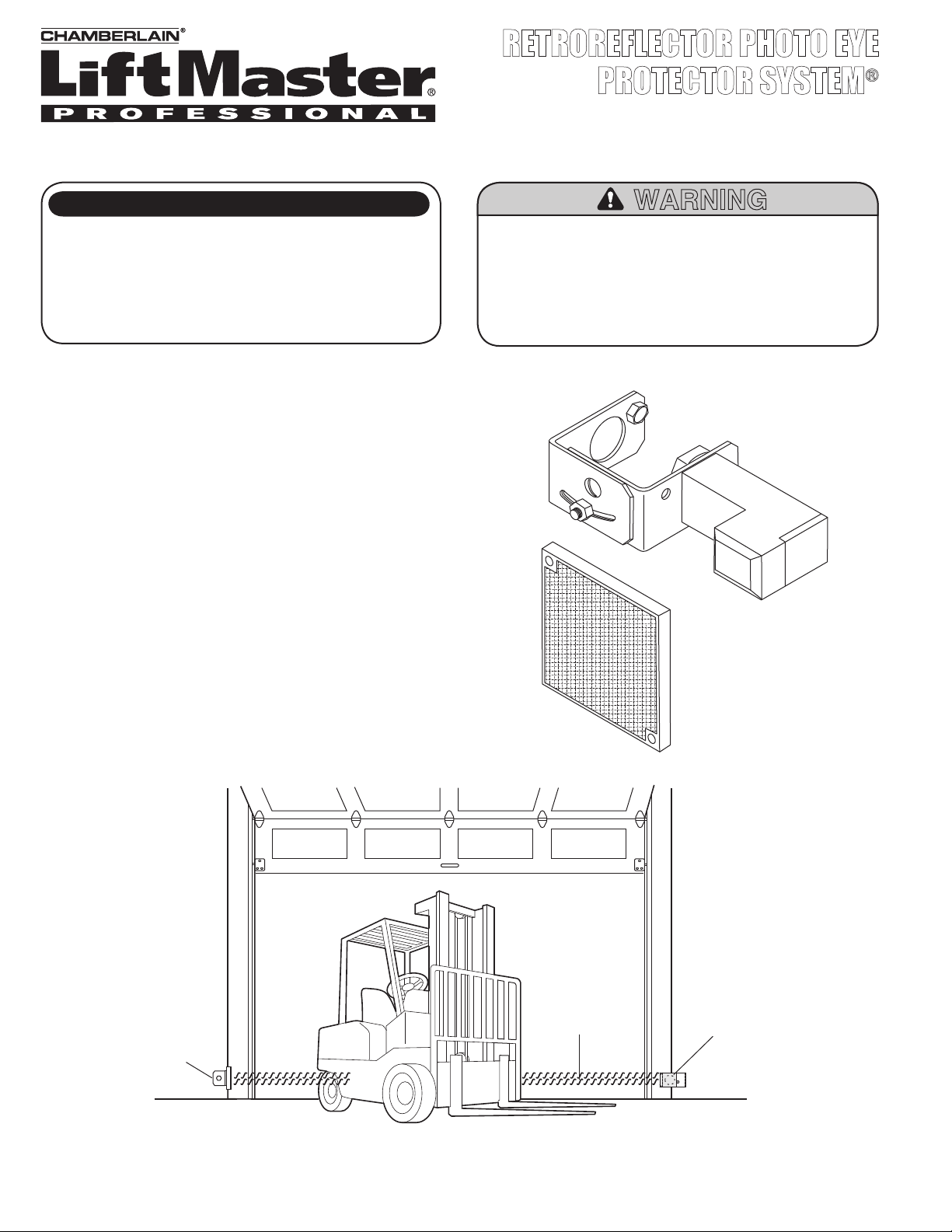
FIGURE 1 Facing the door from inside the garage.
INSTALL THE RETROREFLECTOR PHOTO EYE
PROTECTOR SYSTEM®
Be sure power to the operator is disconnected.
The Retroreflector Photo Eye transmits an invisible light
beam to the Reflector and then bounces the beam back to the
Retroreflector Photo Eye. The units can be installed on either side
of the garage door as long as the sun never shines directly into the
Retroreflector Photo Eye lens.
The brackets must be connected and fastened so that the Reflector
and Retroreflector Photo Eye face each other (Figure 1).
If an obstruction breaks the light beam while the garage door is
closing, the door will stop and reverse to full open position.
The brackets must be securely fastened to a solid surface such
as the studs on either side of the door, or add a piece of wood at
each location if installing in masonry construction.
The invisible light beam path must be unobstructed. No part of
the garage door (or door tracks, springs, hinges, rollers or other
hardware) can interrupt the beam while the door is closing. If
it does, use a piece of wood to build out each sensor mounting
location to the minimum depth required for light beam clearance.
RETROREFLECTOR PHOTO EYE
PROTECTOR SYSTEM®
OWNERS MANUAL
MODEL CPS-RN4
To reduce the risk of SERIOUS INJURY or DEATH,
• This device is for use ONLY on LiftMaster® Commercial
Door Operators.
• Disconnect power BEFORE installing the Commercial
Protector System®.
• Read and follow ALL instructions.
WARNING
NOTE: Mounting bracket for the reflector not included.
ITEM QTY
Retroreflector Photo Eye 1
Retroreflector Photo Eye Bracket 1
Reflector 1
Hardware Bag 1
CARTON INVENTORY
For more information, please visit www.devancocanada.com or call toll free at 855-931-3334

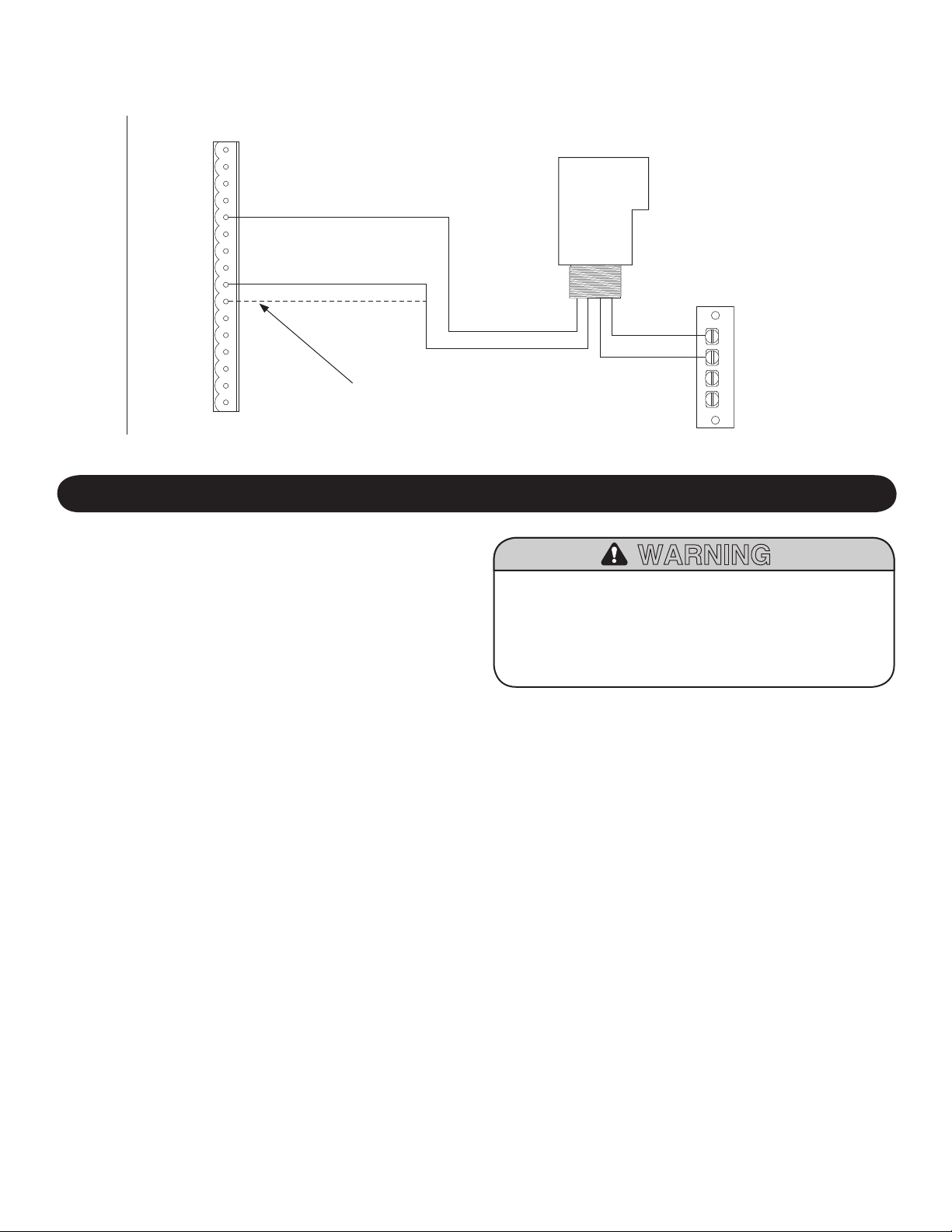
FIGURE 5
FIGURE 2
FIGURE 4
2
See Wiring
Connections
Reflector
Invisible Light Beam
Protection Area
Retroreflector
Photo Eye
Liquid Tight
Conduit
Liquid Tight
Junction Box
Liquid Tight
Junction Box
CONDUIT CONNECTIONS:
Use a liquid tight fitting (1/2" trade size) with
sealing washer to connect to sensors. The sensors
are supplied with 36" long leads. We recommend
the use of a liquid tight junction box near each
sensor to make the connection to the sensor leads
(Figure 5). Use rigid or flexible liquid tight conduit
(depending on local codes) from junction boxes to
operator.
IMPORTANT: Use a copper wire 20 AWG
(minimum) for connection between the Photo Eye
and the operator.
IMPORTANT NOTE: Mount Retroreflector Photo Eye and Reflector
4"-6" above the floor. Do not exceed 6". For sensing above 6" a
second Retroreflector Photo Eye Kit will be required.
INSTALLATION
Hex Mounting
Nut for Photo Eye
Photo
Eye
Lock Washer for
Photo Eye
Hex Nut 1/4"-20
Lock Washer 1/4"
Flat Washer 1/4"
Hex Nut 1/4"-20
Lock Washer 1/4"
Lag Screws
1/4" x 1-1/2"
Track Bolts
1/4"-20 x 5/8"
Track Bolts
1/4"-20 x 5/8"
Track Bolts
1/4"-20 x 5/8"
Drill Holes
1/4"
Hole
Spacing
1/2"
Hole
Spacing
2"
Assemble to either side. Flip one bracket and
assemble to either side.
Door
Track
FLOOR OR WALL MOUNT
For typical floor or wall mounting applications see Figure 2.
If necessary, see Figure 3 for various assembly options to fit
your application. Always use flat washer next to slot with radius
(Figure 2). Insert track bolts through holes as shown.
NOTE: Putting track bolts in slots will prevent brackets from
pivoting. Attach assembly to wall with lag screws provided. To
attach to concrete use concrete anchors (not provided).
TRACK MOUNT
To mount to door track use only one bracket (Figure 4).
To attach vertically to 2" x 4" wall stud and prevent wood from
splitting, bracket may also be rotated with slot on top.
FIGURE 3 Assembly Variations
3
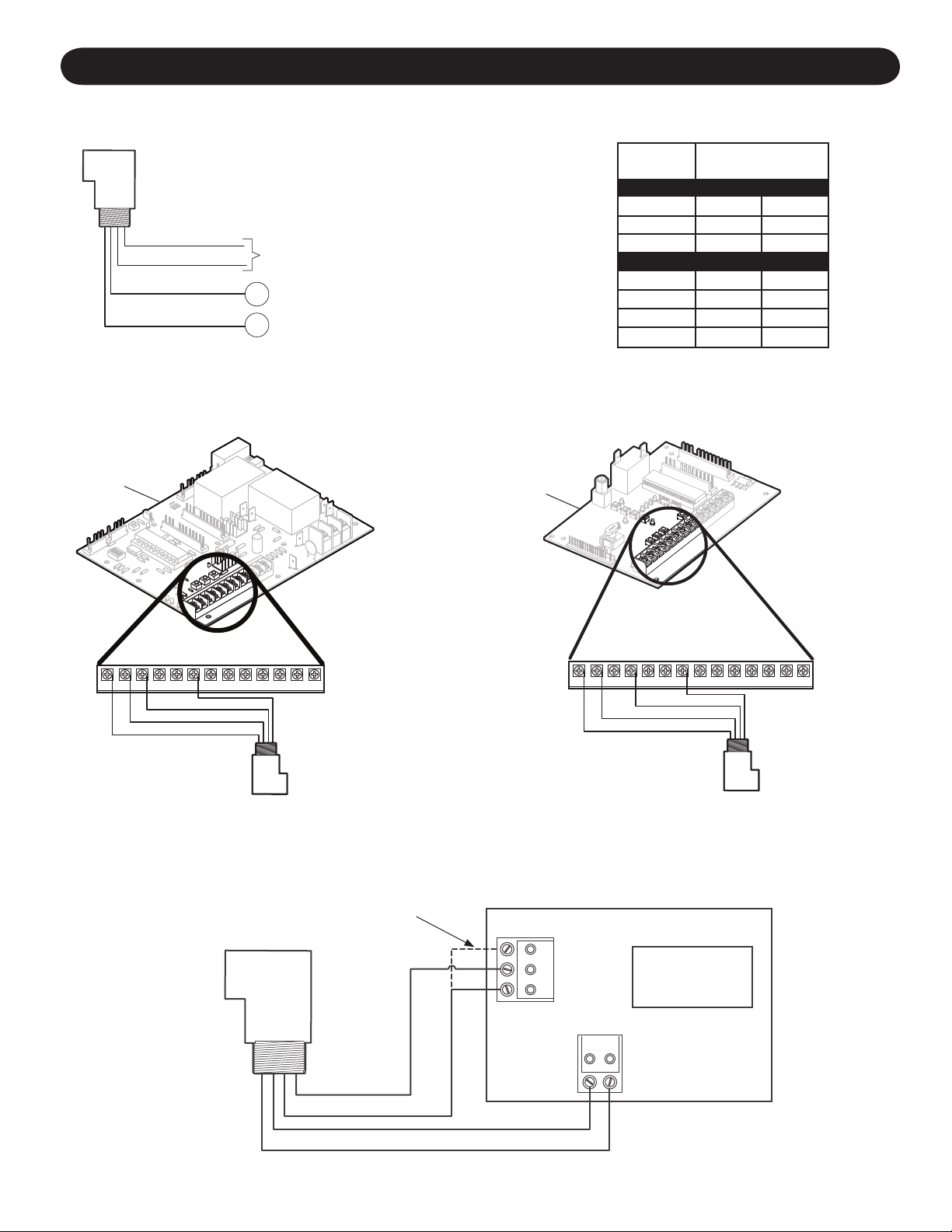
WIRING
A
B
24-250 Vac OR
12-250 Vdc
Brown
Blue
Black
Yellow
(Sensing Input Normally Open)
(Sensing Output Common)
MODEL
10
10
10
3
3
3
TERMINALS
A B
MT
MH
MJ
WIRING CONNECTIONS FOR ELECTRO MECHANICAL OPERATORS
M-LINE
STANDARD LINE
T
GT
GH
HJ
10
10
10
10
3
3
3
3
WIRING CONNECTIONS FOR LIFTMASTER ESTATE SERIES X3 OR B3
CONTROL BOARD
WIRING CONNECTIONS FOR LOGIC 2
OPERATORS
WIRING CONNECTIONS FOR LOGIC 3
OPERATORS
13 12 11 10 9 8 7 6 5 4 3 2 1 1314 12 11 10 9 8 7 6 5 4 3 12
Black
Black
Inside Photo
Outside Photo
Estate Series
X3/B3 Control
Board
24VAC
Output
TB3
Logic 2
Board Logic 3
Board
Yellow
Yellow
Blue
Brown
Black
Yellow
Blue
Blue
Brown
Brown
NOTE: Depending on where you will place the Photo Eye,
use inside photo or outside photo.
NOTE: For all other operators connect black to normally open and
yellow to common, referring to operator instruction manual.
©2008, The Chamberlain Group, Inc
01-16692G All Rights Reserved.
HOW TO ORDER REPAIR PARTS
OUR LARGE SERVICE ORGANIZATION
SPANS AMERICA
FOR INSTALLATION AND SERVICE INFORMATION
SIMPLY DIAL OUR TOLL FREE NUMBER:
1-800-528-2806
www.liftmaster.com
INDICATOR LED’S
GREEN (Power), always lit when power is present. If not lit check power supply and connections of Blue and Brown wires.
RED (SIG), lit and blinking when aligned correctly with the reflector. If LED is not lit check for alignment with reflector and/or clean the
Photo Eye lens and the reflector.
Yellow (OUT), LED will only be lit if obstruction is blocking the invisible light beam, the Yellow and Black wires are grounded or shorted
out or Photo Eye is not aligned with the reflector.
NOTE: For non-logic or solid state operators, if the door is stopped in a position other than fully closed (without activation of the SLS),
activation of the Photo Eye will cause the door to open.
TROUBLE SHOOTING
Test the Retroreflector Photo Eye Protector System®:
• Press the OPEN button to fully open the door.
• Press the CLOSE button to close the door.
• Obstruct the light beam while the door is closing. The
door should reverse.
J1
1
1
2
2
3
3
4
4
6
6
7
7
8
8
11
11
12
12
13
13
14
14
15
15
16
16
5
5
9
9
10
10
GL BOARD
R1
R2
R3
R4
WIRING CONNECTIONS FOR LIFTMASTER OPERATORS
FEATURING GL CONTROL BOARD
To reduce the risk of SERIOUS INJURY or DEATH, the
Commercial Protector System®MUST be properly installed
and working.
Professional service is required if the opener closes the door
when the CDO Commercial Protector System®is obstructed.
WARNING
TESTING THE PROTECTOR SYSTEM®
OPERATION AND MAINTENANCE
NOTE: Depending on where you will place
the Photo Eye, use input 9 for safety open
or input 10 for safety close.
Black
Yellow
Blue
Brown

HOW TO ORDER REPAIR PARTS
DEVANCO CANADA
19192 HAY ROAD, UNIT Q
SUMMERSTOWN, ON K0C 2E0
TOLL FREE: 855-931-3334
www.devancocanada.com
WHEN ORDERING REPAIR PARTS
PLEASE SUPPLY THE FOLLOWING INFORMATION:
3PART NUMBER
3DESCRIPTION
3MODEL NUMBER
Table of contents
Other Chamberlain Protection Device manuals


