Franklin Electric submonitor User manual

Installation & Operation Manual

400 E. Spring Street
Bluffton, IN 46714
Tel: 260-824-2900
Fax: 260-824-2909
www.franklin-electric.com
DECLARATION OF CONFORMITY
Application Of Council Directive(s) 89/336/EEC Electromagnetic Compatibility
73/23/EEC Low Voltage
Manufacturer’s Name \ Address: Franklin Electric Co., Inc.
100 Schaefer Dr.
Gas City, IN 46933
European Representative Name: Dieter Schuch
European Representative Address: Franklin Electric Europa GmbH
Gutenberg Strasse 8
D-54516 Wittlich
Germany
Model Name: SubMonitor
Conformance to Directive(s) Product Standard: EU Directive 89/336/EEC using:
EN 55011:1998, A1:1999 & A2:2002
emissions (See Note 1)
EU Directive 73/23/EEC using:
EN 61010-1:2001
Equipment Type/Environment: Equipment for Measurement, Control &
Laboratory use Light \ Heavy industrial
Note(s)
(1) Product meets emission limit/methods of EN 55011 Class B.
Product meets the immunity levels/methods of EN 61326
Year of Manufacture: 2005
We, the undersigned, hereby declare that the equipment specied above conforms to the
above Directive(s).
Legal Representative in Europe
Franklin Electric Europa GmbH
Full Name
Dieter Schuch
Position
Product Manager
Place
Wittlich Germany
Date March 28, 2005
Manufacturer
Franklin Electric Co., Inc.
Full Name
Quinn Wise
Position
Sr. Project Engineer
Place
Bluffton , IN, USA
Date March 28, 2005

1
Contents
To Set SubMonitor Language ................................................2
SubMonitor Submersible
Pump Motor Protection System ............................................3
Components ...........................................................................4
Installation ............................................................................5-6
Quick Guide to Setup .............................................................7
Additional Programmable Options .......................................8
Password .................................................................................9
Event History ......................................................................... 10
Key Parameters in Event History ........................................ 11
Other Features ...................................................................... 12
Special Conditions ............................................................... 12
Programmable Options ........................................................ 13
Troubleshooting .................................................................... 14
Maintenance ..........................................................................15
Specications ....................................................................... 16
Mounting Dimensions .......................................................... 17
Notes ..................................................................................... 18

To Set SubMonitor Language:
After data sync, from monitoring screen,
Select Menu, press button
Select 5 Detailed Setup, press button
Select K Change Password, press button
Select English, press button
Turn knob until the desired language is displayed, press button to set
Select OK to exit

3
SubMonitor Submersible
Pump Motor Protection System
Franklin’s SubMonitor is an easy to use, programmable protection device
for Franklin Electric three-phase submersible motors.
SubMonitor’s features provide advanced protection of submersible motors:
• SubMonitor operates over the full range of three-phase motor
voltages, 200 - 575 volts, 50 and 60 Hz.
• Operates on motors with service factor current rating of 5 amps
through 350 amps - no external current transformers required.
• Protects motors and pumps from overloads, underloads, overvoltage,
undervoltage, unbalanced currents, phase loss*, chattering contacts,
and phase reversal.
• Operates with a Subtrol-equipped submersible motor to provide
motor winding overheat protection.
• Monitors and displays three-phase voltages, three-phase currents,
and pump status.
• When a fault occurs, displays the fault conditions and status.
• Records and displays the history of up to 502 fault trip events, plus
records changes to programmable parameters.
• Records total pump operating time.
• Features a detachable display unit which may be mounted on the
front of a panel for viewing operating status.
• Includes the option of password protection to avoid tampering.
• Easy mounting with DIN rail mounts.
• Totally integrated unit - current transformers are built in.
Simple Programming
SubMonitor has been pre-programmed with default settings for submersible
motors and pumps. Set-up is as simple as setting the motor ratings - voltage,
Hertz, and SF max amps.
Additional programming options can be selected if desired to customize the
features and levels of protection. See page 7 for an overview of the menu
structure and page 12 for a full list of programmable options.
All programming set-up can be made prior to installing at the eld site by
connecting 230 volts single-phase between voltage inputs L1, L2 and L3 of
SubMonitor (jumper between L2 and L3) and entering the motor data and
any other options.
* Phase loss is a severe case of current unbalance. Reported unbalance trips are
due to phase loss when current on one of the legs (noted in the data log) is very
small, or when the current unbalance function has been disabled.

4 Line
Digital Display
Fault Light (Display)
Menu Selector
Switch
Alarm Circuit
Terminals
Control Circuit
Terminals
Reset Switch Inputs (L1, L2, L3) Fault Light (Base)
Detachable Display Unit
Base Unit
Integrated Sensor Coils
Plug-in Wiring Connectors

5
Installation
FIGURE 1
SubMonitor L1, L2 and
L3 Connections must be
made on the line side of
the contactor as shown
FIGURE 2
FIGURE 3
Start Stop A2
Off
A2
Internal Circuit
*
*Note: This is a TRIAC switch.
WARNING: Hazardous Voltage.
Electrical shock can cause death or serious personal injury.
This equipment should be installed by technically quali ed personnel.
Failure to install in compliance with national and local electrical codes
and within Franklin Electric recommendations may result in electrical
shock or re hazard, unsatisfactory performance, or equipment failure.
L1 L2 L3
L1 L2 L3

SubMonitor Wiring
1. Read this section of the manual thoroughly.
2. Disconnect power & verify that power is off before installing SubMonitor.
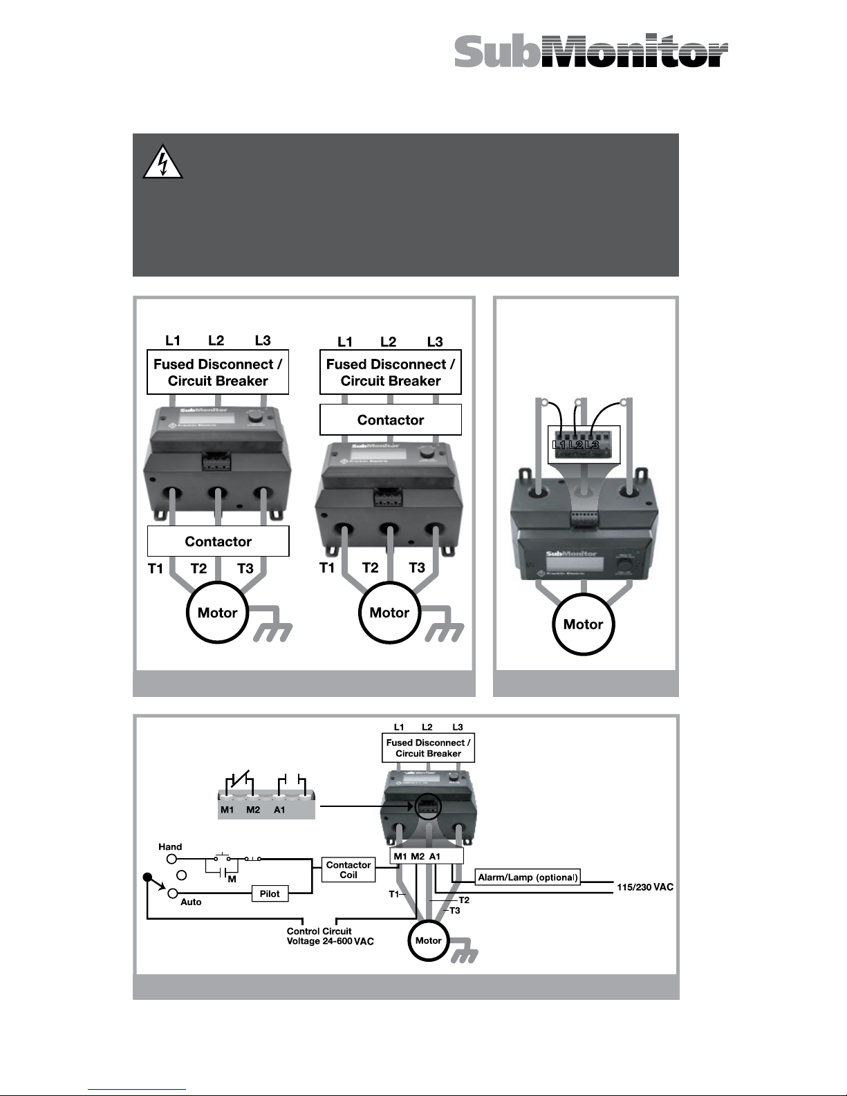
3. Install SubMonitor as illustrated in the wiring diagram in Figure 1.
SubMonitor may be mounted above or below the contactor as shown.
To use the DIN rail mount, rst attach the DIN rail clip to the bottom of
the base unit. Then secure the SubMonitor to the DIN rail. Attach the top
rail rst, then apply downward pressure until the bottom rail snaps into
place.
4. Connect three phase power leads to the plug-in connector L1, L2, and
L3 terminals as shown in Figure 2. Wire strip length is 5/16” (8mm).
The L1, L2, L3 connections must be made to the line side of the
contactor passing through the sensor coils as shown in Figure 2.
(This is because the overheat signal from the motor must rst pass
through the sensor coils, then into the L1, L2, and L3 terminals of
SubMonitor).
5. Connect the control circuit wires to the M1 and M2 plug-in connector
terminals, and signal circuit wires to the A1 and A2 plug-in connector
terminals (Figure 3). Tighten all terminals to 4.5 in-lbs and install the plug-
in connectors into SubMonitor (plugs are keyed to avoid misconnection).
6. Pass the T1, T2, and T3 motor power leads through the sensor coils in
the base unit.
7. NOTE: 6-lead Wye-Delta motors - for a 6-lead motor with a Wye-Delta
control panel, each sensor coil must encircle a pair of leads which connect
to the same line in the delta connection, such as T1-T6; T2-T4 or T3-T5.
8. As an option, the SubMonitor display unit is detachable and can be
mounted on the exterior of the panel door (requires a small punch-out
and two screw holes). Use the extension cable provided in the kit to
connect the base unit to the display unit.
Lightning Arrestor
1. Install the lightning arrestor and connect line leads to the line side of the
contactor as shown in Figure 4.
2. The lightning arrestor ground lead must be connected to water strata
ground to provide suitable surge protection. Connect metal-to-metal to
well casing, drop pipe, or to the
submersible motor with wire the
same size as drop cable wires.
NOTE: Refer to Franklin Electric
Submersible Motor Application,
Installation and Maintenance (AIM)
manual for further discussion of
lightning protection. FIGURE 4

7
Quick Guide to Setup
Points 1 through 3 below describe navigation: how to get around among the
two menus and several screens. Point 4 describes how to change a parameter.
1. On initial power-up, the control circuit will be locked out until the
motor voltage and SF Amps are set. After a 30 second delay while
data sync is completed, the monitor screen will report SF Amps Set Too
High: Locked Out*. Notice MENU in the lower right corner—the arrow
indicates that pressing the knob will take you to the menu Basic Setup.
2. From Basic Setup, rotate to Select Motor and press, and you will
arrive at the Select Motor screen where you can set motor Hz, volts, and
SF Amps (read point 4 below). Set the SF Amps to match the motor SF
Max Amps by adjusting each digit individually. When you are done with
this screen, rotate to OK and press, thereby going back to
Basic Setup.
3. Note that selecting Detailed Setup takes you to a longer menu with
items that are lettered. Select Back: Basic Setup to return to Basic
Setup. Refer to charts on page 7 and page 12 for structure and available
options of menus.
4. When you are on a selected screen of either Basic Setup or Detailed
Setup and you want to change a setting:
a. Rotate the knob until the arrow points to the item to be changed.
b. Press the knob and the arrow will blink. Turning the knob now
changes the value of the item.
c. When the item is correctly adjusted, press the knob and the arrow
stops blinking.
d. You can now rotate the knob to another item on the screen.
Selecting OK returns you to the parent menu.
SubMonitor is now set up to protect your motor and pump, and will allow
the motor to start when you return to the Monitor screen and select Manual
Reset. After any Manual Reset there is a one minute off-time delay
before the motor starts.
Note that the signal circuit and red Fault LED are ON until the motor data is
entered and Manual Reset is pressed.
* Phase Reversal—SubMonitor has a built in phase sequence meter. If
initial power up displays Phase Reversal, the incoming voltage at
SubMonitor’s L1,L2, L3 terminals is negative sequence, and the contactor
is locked out until the phase sequence is corrected.
Figure 2 on page 4 shows SubMonitor inputs L1, L2, and L3 connected
to motor leads T1, T2, and T3 respectively. While this order is not critical
for operation of SubMonitor, it should provide proper motor rotation with
positive sequence line voltage.

Volts
460
462 460
Amps 62 63 61
Pump Running
Menu
Basic Setup
5 Detailed Setup
6 Return to Monitor
1 Enter Password
2 Select Motor
3 Underload Trip
4 Overload Trip
Detailed Setup
L Restore Defaults
M Back: Basic Setup
A Underload Trip
B Overload Trip
C Unbalance Trip
D Overheat Trip
E Overvoltage Trip
F Undervoltage Trip
G False Start Trip
H Restarts
I Time Delays
J Data Logging
K Changes Password
Basic Setup
5 Detailed Setup
6 Return to Monitor
1 Enter Password
2 Select Motor
3 Underload Trip
4 Overload Trip
Volts
460
462 460
Amps 62 63 61
Pump Running
Menu
Additional Programmable Options
The table on page 12 shows the parameters that may be changed in the
Basic Menu and Detailed Menu screens, including the default settings.
Monitor Display
Basic Setup Display
Detailed Setup
Menu
Basic Setup Display
Monitor Display

9
Password
1. The password is factory preset to 0 0 0, which disables the password
protection. With the password protection disabled, all functions in the
menus can be changed by any user.
2. If the password protection is enabled, all parameters in the menus can be
viewed but not changed until the correct password is entered.
3. Using the password function:
a. Go into the Detailed Setup menu and select Change
Password. Enter the three digits of the password sequentially left
to right, just like a combination lock. Select >OK to return to the
Detailed Setup menu.
b. Go to the Basic Setup menu and select Enter Password. Enter
the password sequentially left to right.
4. If you forget your password, refer to the Enter Password screen which
shows a password code. You may call the FE Hotline at 1-800-348-2420
to convert the code into your three digit password.
5. The password resides in the Base Unit. If you change display units, you
will need to know the password that was used with the base unit.
6. If you wish to disable the password protection:
a. Go to Enter Password in the Basic Setup menu. Enter the
correct password.
b. Go to Change Password in the Detailed Setup menu. Enter
the password 0 0 0 sequentially left to right.
7. When a correct password has been entered, changes can be made for the
next 20 minutes. To get another 20 minutes, re-enter the password.
8.
The 20 minute valid password interval is terminated if power is disconnected.
9. If the password protection is enabled, the Event History can be
reviewed after entering the correct password.

Event History
Information Logged
Up to 502 events can be logged and stored in the display unit in a rolling
data set. Information stored includes:
• Event (trip fault, power interruption, etc)
• Time of event (pump run time)
• 3 motor currents
• 3 line voltages
Reviewing Events
• Before events can be reviewed, a valid password must be entered (if
the password is other than 0 0 0).
• Each event is represented by one screen of information.
• Each event is numbered (0-511).
• Each event has a time stamp displayed in days (0-1165), hours (0-23),
minutes (0.0-59.9).The time stamp displayed is the total pump run time.
• You can sequence through the events by turning the knob; CCW goes
backward in time, CW goes forward in time.
• Entering the Event Review system is itself an event that is logged.
This event provides the Total (pump) Run Time. This will be the rst
event shown upon entry into the Event History, and is identied as
“Total Run Time”.
Events Logged
• Total Run Time (always the most recent event)
• Power Up Delay (records power interruptions)
• Tripped : Underload
• Tripped : Overload
• Tripped : Unbalance
• Tripped : Overheat
• Tripped : Overvolt
• Tripped : Undervolt
• Tripped : FalseStart
• Manual Reset
• Protection Change (Trip Point, etc.) (New protection data recorded)
• Defaults Restored (New protection data recorded)
• Motor Change (Hz, Volt, SFA) (New motor data recorded)
When “detailed” logging mode is selected, every switch event and timed
reset is recorded. This mode is typically used only for detailed system
troubleshooting. Additional events logged:
• Timed Reset (Motor Start by SubMonitor)
• Switch On (Motor Start by External Control)
• Switch Off (Motor Stop by External Control)

11
Whenever a setting is changed in the menu, the change is recorded in the
event history as a Parameter Change. The parameter that was changed
is identied with a parameter number per the following table, and the new
setting is recorded.
Parameter
Number Description
0 Motor Rated Frequency
1 Motor Rated Voltage
2 Motor SFA - hundreds digit
3 Motor SFA - tens digit
4 Motor SFA - ones digit
5 Motor SFA - tenths digit
7* Trip Enable Flags
8* Auto Restart Flags
9 Number of Underload Restarts
10 Number of Other Restarts
11 Time Between Starts
12 Power-Up Time Delay
13 Underload Trip Point
14 Timeout for Underload Trip
15 Overload Trip Point
16 Timeout for Overload Trip
17 Unbalance Trip Point
18 Timeout for Unbalance Trip
19 Timeout for Overheat Trip
20 Overvoltage Trip Point
21 Timeout for Overvoltage Trip
22 Undervoltage Trip Point
23 Timeout for Undervoltage Trip
24 Number of False Starts
25 Timeout for False Start Trip
* Flags are binary format (ie. 1101001) where 1=enabled; 0=disabled.
Order of ags: underload, overload, unbalance, overheat, overvoltage,
undervoltage, false start.
For example, for ags 1101001:
Underload, overload, overheat, and false start trips are enabled.
Unbalance, overvoltage, and undervoltage trips are disabled.
Key to Parameters in Event History

FIGURE 5
RESET BUTTON
(1 minute minimum timeout)
GREEN—OK
RED—TRIPPED
PRESS TO
SELECT/EDIT/SAVE
TURN FOR
OPTIONS/ADJUST
M1 M2 A1 A2
K1
K2K2
K1
Contactor
Coil
Contactor
Coil
Control Circuit
Voltage
24-600 VAC
Contactor
Contacts
Contactor
Contacts
Note: The SubMonitor is not
compatible with variable frequency
drives, electronic phase converters, or
solid state soft starters. These devices
will cause nuisance tripping of the
motor overheat fault, or may cause
damage to SubMonitor components.
Reduced voltage starters may be used
with SubMonitor if they are bypassed
during normal running condition
(Figure 5), and if the starting time does
not exceed 3 seconds.
Power Factor or Surge Capacitor—
across-the-line capacitors for
either power factor correction or
surge protection may be used with
SubMonitor. If used, these capacitors
must be connected to the power
supply lines before these lines pass
through the SubMonitor sensor coil
windows or motor overheat protection
may be lost.
Note: At installations where the line voltage is typically 100 to 110%
of nominal, it may be necessary to increase the default underload trip
setting to fully protect the system against underload conditions.
Other Features
Reset
The SubMonitor will not allow a reset for several minutes after a fault trip,
depending on the programmed reset time and fault mode. This allows time
for the motor to cool before it is restarted after a problem has occurred. Any
Manual Reset causes the motor to restart in exactly one minute.
Operation without the Display Unit
After the Select Motor parameters are entered (volts, Hz, and SF Amps),
the base unit of SubMonitor provides full motor protection even when the
Display Unit is disconnected.
When operating with a Base Unit only:
• A “run enable” condition is indicated by a green LED
• A trip condition is indicated by a red Fault LED
• Manual reset is initiated by pressing the Reset Switch
• The Event History is not recorded (total run time is recorded).
Special Conditions

13
Default (On / Off)
Trip Point Settings Timeout Settings
Default Setting
Adjustable Range
Default Setting
Adjustable Range
General Parameters
Min
Max
Increment
Min
Max
Increment
minutes / seconds
Restart Attempts - Underload On 3 0 10* 1 Restarts
Restart Attempts - All Other On 3 0 10* 1 Restarts
Time Between Starts 1 0 10 1 min
Power Up Delay 30 10 120 10 sec
Specic Parameters
Underload On 75% 30% 100% 5% of SFA 30 10 120 10 min
Overload On 115% 80% 125% 5% of SFA 10 5 60 5 min
Undervoltage On 90% 80% 90% 2% of Vrated 1 1 15 1 min
Overvoltage On 110% 110% 120% 2% of Vrated 1 1 15 1 min
Current Unbalance On 5% 2% 10% 1% 10 5 60 5 min
Overheated Motor On 10 5 60 5 min
False Start (Chattering) On 10 3 15 1 starts in 10 sec. 1 1 15 1 min
* Unlimited restarts (**) may also be selected.
Programmable Options

Fault Message Problem / Conditions Possible Cause
SF Amps Set Too High SF Amps setting
above 350 Amps Motor SF Amps not entered
Phase Reversal Reversed incoming
voltage phase sequence Incoming power problem
Overrange Measured voltage or
current is exceeding the
selected motor settings
Wrong Motor Voltage or SFA
Setting
Excessively high line voltage
or motor current
Underload
Normal line current Wrong SF Max Amps setting
Low line current
Over pumping well
Clogged pump intake
Closed valve
Loose pump impeller
Broken shaft or coupling
Phase loss
Overload
Normal line current Wrong SF Max Amps setting
High line current
High or low line voltage
Ground fault
Pump or motor dragging
Motor stalled or bound pump
Overheat
Motor temperature
sensor has detected
excess motor winding
temperature
High or low line voltage
Motor is overloaded
Excessive current unbalance
Poor motor cooling
High water temperature
Excessive electrical noise
(VFD in close proximity)
Unbalance Current difference between
any two legs exceeds
programmed setting
Phase loss
Unbalanced power supply
Open delta transformer
Overvoltage Line voltage exceeds
programmed setting Unstable power supply
Undervoltage Line voltage below
programmed setting
Poor connections in motor
power circuit
Unstable or weak power supply
False Starts Power has been
interrupted too many times
in a 10 second period
Chattering contacts
Loose connections in motor
power circuit
Arcing contacts
Troubleshooting

15
Symptom Possible Cause or Solution
SubMonitor Dead
If the line voltage is correct at the SubMonitor’s L1, L2 and
L3 terminals and the display is blank, remove display and
check cable connections. If cable connections are ok, then
SubMonitor is malfunctioning.
SubMonitor’s Screen
Does Not Change from
Franklin Electric Screen
Check for a broken or disconnected communications cable
from base to display. If cable is ok, then SubMonitor is
malfuctioning.
Display reads
“Phase Reversal”
SubMonitor has a built-in phase sequence meter to assure
once properly installed, a change in incoming power sequence
cannot cause the pump to run backwards. If the display reads
“Phase Reversal” the SubMonitor thinks the motor will run in
the wrong direction.
On a new installation, after verifying proper motor rotation,
switch power leads L1 and L2 on top of the SubMonitor. DO
NOT CHANGE THE MOTORS LEADS.
On an old installation that was working ne, verify proper
motor rotation and/or switch motor leads T1 and T2 at the
starter as needed. DO NOT CHANGE THE SUBMONITOR
POWER LEADS.
Tripped Light On
Whenever the pump is off as a result of SubMonitor protective
function, the red tripped LED (light) on the display and base will
turn on.
Control Circuit Fuse
Blows
With power turned off, check for a shorted contractor coil or a
grounded control circuit lead. The coil resistance should be at
least 10 ohms and the circuit resistance to panel frame should
be over 1 megohm. A standard or delay-type 1.5 Amp fuse
should be used.
SubMonitor Contactor
Will Not Close
If proper voltage is at the control coil terminals when controls
are operated to turn the pump on, but the contactor does not
close, turn off power and replace the coil. If there is no voltage
at the coil, trace the control cirucit to determine if the fault is in
the fuse, wiring or panel operating switches. This tracing can
be done by rst connecting a voltmeter at the coil terminals and
then moving the meter connections step by step along each
circuit to the power source, to determine at which component
the voltage is lost.
Contactor Hums or
Chatters
Check that coil voltage is within 10% of rated voltage. If voltage
is correct and matches line voltage, turn off power and remove
the contactor magnetic assembly to check for wear, corrosion
or dirt. If voltage is erratic or lower than line voltage, trace the
control circuit for faults similar to the previous item, but looking
for a major drop in voltage rather than its complete loss.
Contactor Opens When
Start Switch is Released
Check that the small interlocks switch on the side of the
contactor closes when the contactor closes. If the switch or
circuit is open, the contactor will not stay closed when the
selector switch is in HAND position.
Contactor Closes But
Motor Doesn’t Run
Turn off power. Check the contactor contacts for dirt, corrosion
and proper closing when the contactor is closed by hand.
Maintenance

Electrical
Input Voltage 3-Phase 190-600 VAC
Frequency 50 Hz or 60 Hz
Motor SF (Max) Amps Range 5 amps to 350 amps
Maximum Conductor Size Through
Sensors
0.92” diameter, #0000 AWG Max
23 mm diameter, 95 mm2 gauge max
Measurement Accuracy *
Voltage 1% ± 1 digit
Current 1% ± 1 digit
Trip Time - Locked rotor, underload,
overload, overheat, unbalance,
overvoltage, undervoltage 3 seconds
Input Current, L1, L2, L3 0.15 amps
Control Circuit Rating 1.5 amp AC, up to 600 volts
Signal Circuit Rating 1 amp AC, up to 250 volts
Incandescent lamp, 100 watts max
Agency Approvals
UL 508 classication NKCR, NKCR7 le
E160632
cUL
Standards Met
Surge ANSI/IEEE C62.41
Electrical Fast Transient IEC 1000-4-4 Level 4, 4kV
ESD IEC 1000-4-2 Level 3, 6kV
Mechanical
Dimensions (WxHxD)
Base Unit 8.0” x 5.35” x 4.3” (20.3 x 13.6 x 10.9 cm)
Display Unit 7.0” x 3.0” x 1.4” (17.8 x 7.6 x 3.6 cm)
Total Unit 8.0” x 5.35” x 5.7” (20.3 x 13.6 x 14.5 cm)
Weight
Base Unit 46 oz (1.3 kg)
Display Unit 7 oz (0.2 kg)
Total Unit 53 oz (1.5 kg)
Operating Temperature Range -20 °C to +60 °C
Storage Temperature Range -30 °C to +80 °C
Relative Humidity 10-95% non-condensing
Protection Class
Display Unit NEMA 3R
Base Unit NEMA 1
Specications
* When Strong radio frequency energy is present, SubMonitor measurement
accuracy (voltage and current) is ± 3%. Contact Franklin Electric technical
support for assistance with these types of installations.

17
Mounting Dimensions
6 ¾”
(171.45 mm)
4.72”
(119.89 mm)
5 ¾”
(146.05 mm)
Slot ¼” (6.35 mm) Dia. Max. 4 Places
#8 Flathead Screw
1 ½” (19.05 mm) Long
2 Places
¾”
(19.05 mm)
1 ½” (19.05 mm) Dia. Clearance Hole
in Control Panel Cover for RJ Cable
Install Gasket Between
the Panel and the Back
of the Display Unit
For Mounting Detachable Display Unit on the Cover of a Control Panel
2 7
/8”
(73.03 mm)

Notes
TOLL-FREE HELP FROM A FRIEND
Franklin Electric
Submersible Service Hotline
800-348-2420
Other manuals for submonitor
1
Table of contents
Other Franklin Electric Protection Device manuals
Popular Protection Device manuals by other brands

Eaton
Eaton Crouse-Hinds GFS Series Installation & maintenance information

Sealey
Sealey WORKSAFE SSP19CO manual

Arcserve
Arcserve 7100 quick start guide

nvent
nvent ERICO Early Streamer Emission System 1000 Installation, operation and maintenance manual

Safelab
Safelab AIRONE 1000R instruction manual

SOMFY
SOMFY J4 io Short installation guide