I+ME ACTIA BOP HD8 User manual

User Manual
BOP HD8 / BOP HD16
Ref.: IR1212828 A 21.08.2009 Edition 1.0 Page 1/87
I+ME ACTIA GmbH
I + ME ACTIA
Informatik und Mikro-Elektronik
GmbH
Dresdenstrasse 17/18
D-38124 Braunschweig
Germany
Tel.: ++ 49 (0) 531 38701-0
Fax: ++ 49 (0) 531 38701-88
www.ime-actia.com
User Manual
BOP HD8 / BOP HD16
Edition 1.0
Dokumentenvorla
g
e Erstellt von/am: R&D/ 16.03.2009 IR11263E

User Manual
BOP HD8 / BOP HD16
Ref.: IR1212828 A 21.08.2009 Edition 1.0 Page 2/87
I+ME ACTIA GmbH
Document Reference
Interne Mailing List External Mailing ListClassification
Name Department Name Department
Without
Confid. I+ME
Confid.Client
Status only for Information Official Document
Release Date: 21.08.2009
Initials Ref. I+ME Index
Autor
WLA
IR12128 A
approved
TME © I+ME ACTIA GmbH 2009
Document History
Index Page Date Reason of Change Name
© 2009 I+ME ACTIA GmbH All Rights reserved.
Any reproduction or distribution of this document,
or parts of this document is prohibited without a
written authorisation of I+ME ACTIA GmbH.

User Manual
BOP HD8 / BOP HD16
Ref.: IR1212828 A 21.08.2009 Edition 1.0 Page 3/87
I+ME ACTIA GmbH
Content
1.
Introduction ........................................................................................................7
1.1
This manual......................................................................................................7
1.2
Warranty..........................................................................................................8
1.3
For safety.........................................................................................................8
1.4
Intended use ....................................................................................................8
1.5
Function...........................................................................................................9
1.6
Used Symbols and notation.................................................................................9
2.
General system describtion – BOP HD ...................................................................11
2.1
Front side - BOP HD.........................................................................................13
2.1.1.
Key switch .............................................................................................13
2.1.2.
Operating status display...........................................................................14
2.1.3.
LAN interface..........................................................................................15
2.1.4.
Data storage ..........................................................................................15
2.1.5.
Reset switch ...........................................................................................16
2.2
Rear panel - BOP HD........................................................................................17
2.2.1.
Video in – Camera adapters......................................................................17
2.2.2.
Video out – Monitor adapters ....................................................................17
2.2.3.
USB Ports ..............................................................................................18
2.2.4.
LAN Interface .........................................................................................18
2.2.5.
Plug 1 – 18 PIN.......................................................................................19
2.2.5.1
Microphones ........................................................................................19
2.2.5.2
Digital out ...........................................................................................19
2.2.6.
Plug 2 – 21 PIN.......................................................................................20
2.2.6.1
Power supply (Clamp 30).......................................................................20
2.2.6.2
Ignition (Clamp 15) - BOP HD on/off .......................................................20
2.2.6.3
IBIS Interface ......................................................................................20
2.2.6.4
CAN-Interface ......................................................................................21
2.2.6.5
digital in..............................................................................................21
3.
Installation........................................................................................................ 22
3.1
Assembly .......................................................................................................23
3.2
Connection diagramm ......................................................................................24
3.3
Interfaces / Integration of the BOP HD ...............................................................25
3.4
Plug 1 – 18PIN................................................................................................26
3.5
Plug 2 – 21PIN................................................................................................27
3.6
Connection of the Power supply .........................................................................28
3.7
Ignition Connection..........................................................................................28
3.8
Connection of door contact, reverse gear, alarm switch etc....................................28
3.9
Connection of Cameras ....................................................................................29
3.10
Connection of microphones..........................................................................30
3.11
Connection of monitors ...............................................................................30
3.12
CAN Connection......................................................................................... 30
3.13
GPS receiver .............................................................................................31
3.14
IBIS.........................................................................................................31
3.15
Other peripheral devices .............................................................................31
4.
Commissioning / Configuration.............................................................................32
4.1
External access ...............................................................................................33
4.1.1.
Video Streaming .....................................................................................33
4.1.2.
Alarm over Ethernet ................................................................................33
5.
Operation of the BOP HD.....................................................................................34
5.1
Data storage - assemble and change..................................................................35
5.2
Data storage - storage and transport..................................................................36
6.
The BOP HD Web Interface ..................................................................................38
6.1
Start of the BOP HD Web Interface ....................................................................39
6.2
Live pictures ...................................................................................................40
6.3
Maintenance ...................................................................................................41

User Manual
BOP HD8 / BOP HD16
Ref.: IR1212828 A 21.08.2009 Edition 1.0 Page 4/87
I+ME ACTIA GmbH
6.3.1.
Error file err.txt..................................................................................... 41
6.3.1.1
How to open the error file ......................................................................41
6.3.1.2
How to delete the error file ....................................................................41
6.3.1.3
Design of the error file ..........................................................................42
6.3.2.
Log file log*.txt.....................................................................................43
6.4
Configuration ..................................................................................................44
6.4.1.
Info line.................................................................................................45
6.4.2.
Date and time.........................................................................................45
6.4.2.1
PC Date and time .................................................................................46
6.4.2.2
BOP HD-RTC Date and time ...................................................................46
6.4.2.3
BOP HD-System Date and time...............................................................46
6.4.3.
General settings......................................................................................47
6.4.3.1
Language ............................................................................................47
6.4.3.2
Identification of the vehicle ....................................................................47
6.4.3.3
Sequence time .....................................................................................47
6.4.3.4
Shutdown delay ...................................................................................48
6.4.3.5
Pre-alarm / Post-alarm.......................................................................... 48
6.4.3.6
Alarm buffer limit .................................................................................48
6.4.3.7
Maximum buffer time ............................................................................49
6.4.3.8
24V Error check ...................................................................................49
6.4.3.9
Error signaling time ..............................................................................50
6.4.3.10
Single error signal ...............................................................................50
6.4.3.11
CAM problem -> error..........................................................................50
6.4.4.
Video settings.........................................................................................51
6.4.4.1
Frame size...........................................................................................51
6.4.4.2
Frame rate divisor ................................................................................51
6.4.4.3
Compression / Quality...........................................................................52
6.4.4.4
GOP time ............................................................................................52
6.4.4.5
Adaptive frame rate ..............................................................................52
6.4.4.6
Streaming mode...................................................................................53
6.4.4.7
Text insertion (OSD) .............................................................................53
6.4.4.8
Video out #1 mapping...........................................................................54
6.4.4.9
V-Input On/Off.....................................................................................54
6.4.5.
Audio settings.........................................................................................54
6.4.5.1
Audio channels..................................................................................... 54
6.4.6.
Video output 1 ........................................................................................ 55
6.4.6.1
Automatic cycling .................................................................................55
6.4.6.2
Cycling control .....................................................................................56
6.4.6.3
Non-cycling video input (Standard video in) .............................................57
6.4.6.4
Reverse camera ...................................................................................57
6.4.6.5
Door camera........................................................................................57
6.4.7.
Video output 2 ........................................................................................ 58
6.4.7.1
Automatic cycling .................................................................................58
6.4.7.2
Cycling control .....................................................................................58
6.4.7.3
Non-cycling video input (Standard video in) .............................................58
6.4.8.
Relays ...................................................................................................59
6.4.8.1
Automatic relay control ......................................................................... 59
6.4.8.2
Alarm output .......................................................................................59
6.4.8.3
Alarm signaling ....................................................................................60
6.4.9.
IBIS ......................................................................................................60
6.4.9.1
IBIS time adjustment............................................................................60
6.4.9.2
Automatic system restart.......................................................................61
6.4.10.
Network access parameters ......................................................................62
6.4.10.1
IP - Address / Netmask ........................................................................ 62
6.4.10.2
IP - Address / Netmask (rear panel).......................................................62

User Manual
BOP HD8 / BOP HD16
Ref.: IR1212828 A 21.08.2009 Edition 1.0 Page 5/87
I+ME ACTIA GmbH
6.4.10.3
Gateway ............................................................................................63
6.4.10.4
Nameserver1 / Nameserver2 ................................................................63
6.4.10.5
Broadcast destination address...............................................................63
6.4.10.6
Alarm rx OFF/ON.................................................................................63
6.4.11.
Error log and alarm video file transfer ........................................................64
6.4.12.
Reload / Save / Save + Restart .................................................................65
6.5
Configuration Load/Save – Firmware upload........................................................66
6.5.1.
How to save the current configuration ........................................................66
6.5.2.
How to load a configuration / How to load a Configuration with restart............67
6.5.3.
How to load a firmware ............................................................................67
6.6
Administrator..................................................................................................69
6.6.1.
Passwords..............................................................................................70
6.6.2.
Access to the data storage........................................................................71
6.6.2.1
Operation ............................................................................................71
6.6.2.2
Structure and content ...........................................................................72
6.6.3.
How to format the data storage.................................................................73
7.
Data analysis.....................................................................................................74
7.1
The BOP Reviewer Software ..............................................................................74
8.
Annex ..............................................................................................................76
8.1
Abbreviations and Glossary...............................................................................76
8.2
Technical data – video protection system BOP HD ................................................77
8.2.1.
System data...........................................................................................77
8.2.2.
Technical data ........................................................................................78
8.2.3.
Ethernet - interfaces................................................................................ 79
8.2.4.
Recording time .......................................................................................80
8.3
Dimensional drawings ......................................................................................81
8.4
Error messages / the file err.txt......................................................................... 82
8.5
Certificates and approvals.................................................................................85
8.6
Accessories.....................................................................................................85
8.7
Network and browser settings at the PC / Notebook .............................................86
8.7.1.
Network connection via cabel ....................................................................86
8.7.2.
Microsoft Internet Explorer .......................................................................87
8.7.3.
Mozilla Firefox.........................................................................................87
8.7.4.
How to open the connection......................................................................87

User Manual
BOP HD8 / BOP HD16
Ref.: IR1212828 A 21.08.2009 Edition 1.0 Page 6/87
I+ME ACTIA GmbH

User Manual
BOP HD8 / BOP HD16
Ref.: IR1212828 A 21.08.2009 Edition 1.0 Page 7/87
I+ME ACTIA GmbH
1.
I
NTRODUCTION
1.1 T
HIS MANUAL
This manual describes the I+ME ACTIA video protection system BOP HD.
Variants:
BOP HD8 (8 x video in)
BOP HD16 (16 x video in)
BOP HD-Reviewer Station
This information serves
to get close to the video protection system BOB HD
to operate with the video protection system BOP HD in a safely, suitable and
economically manner
Respecting these information will degrade risks, reduce repairs and downtimes and
increase the reliability and lifetime of the system and the attached equipment.
Each person operating with the video protection system BOP HD must observe the
instructions in this manual.
The manual has to be completed by national regulations (particularly to the data privacy
protection).
If necessary a separate documentation for special users must be created by the operating
company.
The operating company and the user are responsible for the correct use of the video
protection system BOP HD.
Changes, rebuilding or other interferences into the video protection system BOP HD are
not allowed. Service is only allowed if executed by qualified technicians. We do not accept
responsibility for incorrect service or modifications made by the user or third party.

User Manual
BOP HD8 / BOP HD16
Ref.: IR1212828 A 21.08.2009 Edition 1.0 Page 8/87
I+ME ACTIA GmbH
1.2 W
ARRANTY
The term of warranty fort he video protection system BOP HD is 24 months from date of
purchase unless otherwise agreed. During the term of warranty we will repair all defects
the reasons of which are proven to be defects of material or manufacturing. Excluded from
the warranty are damages resulting from inappropriate use or normal wear and tear.
Warranty is granted on the basis of legal standards with an expressive authorization for
repair work to be effected.
For complains please return the tool to your professional dealer or send it freight prepaid
to I+ME ACTIA.
1.3 F
OR SAFETY
Only skilled staff may install and commissioning the video protection system BOP HD.
The general safety instructions by handling with electrical equipment must be observed.
At the selection of the mounting place for the ACTIA video protection system BOP HD the
corresponding specifications and regulations must be observed.
At the integration and operation of the ACTIA video protection system in a vehicle,
interference to the function of the vehicle must be excluded. Especially safety systems
may not be disturbed or set out of function.
1.4 I
NTENDED USE
The ACTIA video protection system BOP HD is designed for the exclusive use of recording
and analysing video and audio data as well as the related additional information in
vehicles by considering of the legal master regulations

User Manual
BOP HD8 / BOP HD16
Ref.: IR1212828 A 21.08.2009 Edition 1.0 Page 9/87
I+ME ACTIA GmbH
1.5 F
UNCTION
The ACTIA video protection system BOP HD records the video and audio data of the
attached cameras, microphones and peripheral devices (e.g. GPS) as well as additional
information from the vehicle. The data will be stored on removable data storage (hard
disk).
The analysing happens directly (live-view, alarm data transfer) or later by checking the
stored data by the use of the BOP Reviewer Software.
The data at an alarm are stored separately. This data could be automatically transferred
to an external registration office by the use of a external modem.
The system is especially designed for the integration in public transport such as buses and
trains.
1.6 U
SED
S
YMBOLS AND NOTATION
The following signs and syntax are used in this manual.
Safety instructions and warnings
are marked with the attention sign. A keyword specifies the note.
Special information is marked with this symbol.
This reference symbol is used in order to guide the user to other chapters of this
manual or additional literature.
>Text< Text or values in the context of screen forms are marked by pointed
brackets.
>Text< Text or values in the context of input fields are bold and marked by pointed
brackets.
[OK] Operating elements – like buttons and switches are marked by square brackets.

User Manual
BOP HD8 / BOP HD16
Ref.: IR1212828 A 21.08.2009 Edition 1.0 Page 10/87
I+ME ACTIA GmbH

User Manual
BOP HD8 / BOP HD16
Ref.: IR1212828 A 21.08.2009 Edition 1.0 Page 11/87
I+ME ACTIA GmbH
2.
G
ENERAL SYSTEM DESCRIBTION
–
BOP
HD
The BOP HD is a digital video protection system especially for the use in public transport
such as buses and trains.
The system is placed in a robust metal case. It allows the real time digital recording from up
to 8 (16) analogue video signals (PAL or NTSC) in MPEG4/H.264 format, up to 2 audio
tracks, the actual GPS position information (by the use of a optional GPS-mouse) as well as
the additional information from environmental systems (IBIS data, CAN information, switch
signals, …).
The recording starts by the ignition (clamp 15) or a digital input (wakeup function). The
data are stored in a ring buffer (controlled by the capacity or time). This method ensure the
recording of the actual data, even the data storage is full.
Data which are recorded during an alarm (triggered by CAN, a digital input or Ethernet
broadcast) are stored at a save area. This area could not be overwritten by the ring buffer.
The data could be displayed to the attached monitors during the recording. Data which are
stored during an alarm (alarm data) could be transferred automatically by the use of an
external modem.
The configuration is made by an easy to use web interface.

User Manual
BOP HD8 / BOP HD16
Ref.: IR1212828 A 21.08.2009 Edition 1.0 Page 12/87
I+ME ACTIA GmbH
To analyse the data the BOP Reviewer Software from I+ME ACTIA could be used.
Main components
BOP HD with
- CPU and graphics processor
- Linux operating system and BOP HD firmware
- video- and audio interface electronic
- Ethernet, USB
- digital in / digital out
- integrated power supply without fan for adapted components
Exchangeable data storage with up to two 2.5’’ SATA hard disks
- for storage of the video- , audio and additional data.
Additional components (not in the scope of delivery)
BOP Reviewer Software
additional data storage
cameras (mini dome, dome and special cameras)
monitors
cable sets for connecting cameras, switches, monitors and the power supply.
adapter sets for easy integration into vehicles
mounting bracket (to save prior unauthorized removal, the device could only be
removed with a key)
User Manual
BOP HD8 / BOP HD16
Ref.: IR1212828 A 21.08.2009 Edition 1.0 Page 13/87
I+ME ACTIA GmbH
2.1 F
RONT SIDE
-
BOP
HD
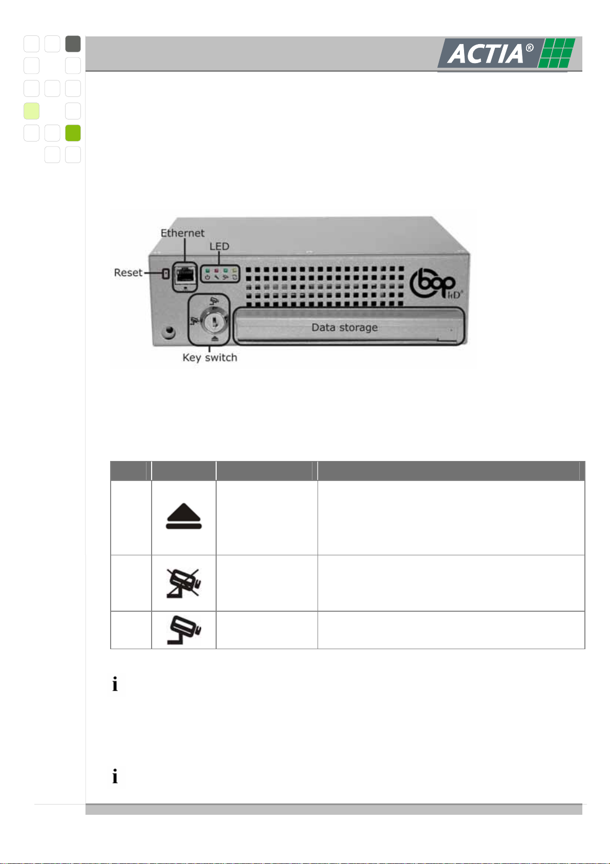
At the front panel all control elements and gauges are arranged. The Ethernet connector
for configuration and maintenance is also placed at the front panel. Normally after the
integration the BOP HD must not dismounted for maintenance and configuration.
2.1.1. K
EY SWITCH
By the key-switch the BOP HD is set to the following operation modes.
Pos. Symbol Mode Note
1 OFF
The BOP HD is off/ is switched off.
After the automatically disabling of the
electromagnetic locking the data storage could
be detached.
2 PAUSE
The BOP HD switches offline.
No data will be recorded.
For maintenance and reviewing.
3 RECORD The BOP HD records video and audio data
according to the settings in the configuration.
Only authorized staff may switch the mode.
Remove the key-switch to protect prior unauthorized change of the operation
mode.
At switch-on a self test is executed (from >OFF< to >PAUSE< or >AUFNAHME<).
User Manual
BOP HD8 / BOP HD16
Ref.: IR1212828 A 21.08.2009 Edition 1.0 Page 14/87
I+ME ACTIA GmbH
At an error the red service LED is flashing and the event is stored into the error file.
The change of the operation mode is receipted by a short concurrent flash of the
LED`s “Record” and “Data transmission”. The switching of the operation mode
takes same seconds.
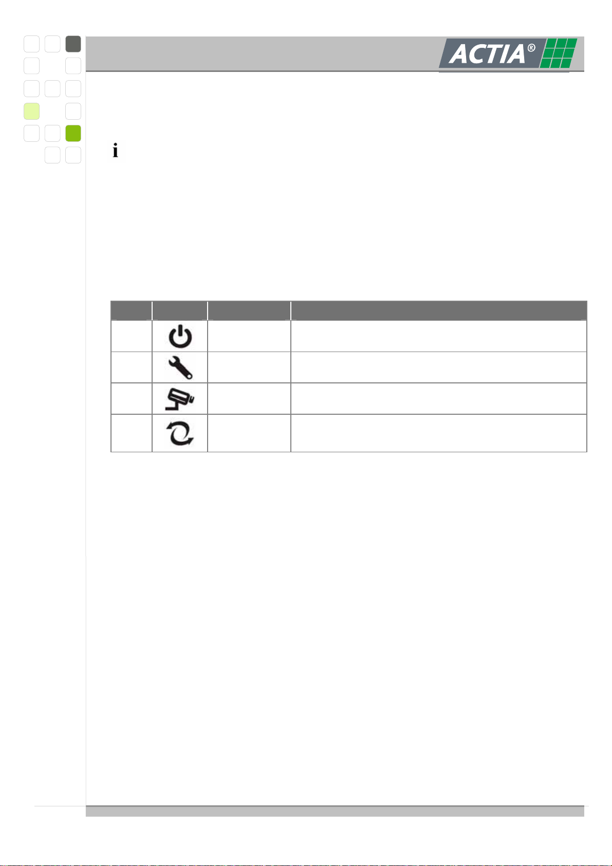
2.1.2. O
PERATING STATUS DISPLAY
Four light emitting diodes signalling the operation status of the BOP HD.
Pos. Symbol Status Note
1 Power on Green flashing when power supply is active.
2 Service Red blinking at a malfunction.
3 Record Green blinking during data recording.
4
Data
transmission
Yellow blinking at an access to the data storage
(read / write).

User Manual
BOP HD8 / BOP HD16
Ref.: IR1212828 A 21.08.2009 Edition 1.0 Page 15/87
I+ME ACTIA GmbH
2.1.3. LAN
INTERFACE
The Ethernet interface at the front panel is used for
system configuration (by use of the web interface)
password protected data transfer via SMB/CIFS
update of the system
The Ethernet interface equates to IEEE802.3 BaseT with automatically detection of
the transfer rate of 10/100 Megabit.
A standard network cable with RJ45 plug can be used if the connected PC supports
auto crossing. Otherwise a crosslink cable is needed.
See also chapter 8.2.3
2.1.4. D
ATA STORAGE
The exchangeable data storage contains up to two 2.5’’ hard disks.
Depending on the size of the hard disks, the numbers of video channels to be recorded
and the image resolution recording, recording times with more then 200 hours are
possible.
See also chapter 8.2.4
We advise to format the data storage before use. This makes sure that all old data
are deleted and the full capacity is useable.

User Manual
BOP HD8 / BOP HD16
Ref.: IR1212828 A 21.08.2009 Edition 1.0 Page 16/87
I+ME ACTIA GmbH
2.1.5. R
ESET SWITCH
Danger of data loss
By restarting the BOP HD via the reset switch data can be lost.
The BOP HD is reset by the reset switch. The system runs a complete restart. Only use the
reset switch in exceptional cases (e.g. the BOP HD is in undefined state).
The reset switch is provided behind the front cover. This protect it prior unintended use.
The reset switch can be pressed by a small bolt.

User Manual
BOP HD8 / BOP HD16
Ref.: IR1212828 A 21.08.2009 Edition 1.0 Page 17/87
I+ME ACTIA GmbH
2.2 R
EAR PANEL
-
BOP
HD
At the rear panel all connectors to connect the BOP HD to the vehicle and the peripheral
devices are arranged.
2.2.1. V
IDEO IN
–
C
AMERA ADAPTERS
Up to 8 (16) cameras can be attached to the BOP HD.
A large range of cameras are available at I+ME ACTIA. We advise to use only
cameras which are released by I+ME ACTIA. You obtain detailed information from
your specialist dealer or directly from I+ME ACTIA.
2.2.2. V
IDEO OUT
–
M
ONITOR ADAPTERS
Two analogue monitors can be served by the both video out. A multiplexer is available via
software. Therewith the display of one video channel constant or several video channels
alternating is possible at each monitor. The alternating display can be switched on/off be
the use of a digital input.

User Manual
BOP HD8 / BOP HD16
Ref.: IR1212828 A 21.08.2009 Edition 1.0 Page 18/87
I+ME ACTIA GmbH
Additional an integrated video processor makes it possible to display several video signals
at the same time on the monitor.
A large range of monitors are available at I+ME ACTIA. We advise the only use of
monitors which are released by I+ME. You obtain detailed information from your
specialist dealer or directly from I+ME ACTIA.
2.2.3. USB
P
ORTS
Two high speed USB ports are available to connect external devices.
Specification of the USB ports
USB 2.0
USB Type A plug
Power supply for external devices: 5V, max. 500mA (with overload protection)
Transfer rate: 480 MBit
Overload protection up to 15 kV
2.2.4. LAN
I
NTERFACE
The Ethernet interface at the rear panel is used for
Integration of BOP HD into a network.
(streaming, broadcast, download, reviewing, ...)
Connection of an interface converter Ethernet to WLAN, GPRS, EDGE or UMTS.
Therefore such devices could be connected to the BOP HD.
The Ethernet interface equates to IEEE802.3 BaseT with automatically detection of
the transfer rate of 10/100/1000 Megabit and auto crossing. A standard network
cable with RJ45 plug can be used.
Also the web interface for the system configuration could be connected via the
Ethernet at the rear panel (see chapter 6).
See also chapter8.7

User Manual
BOP HD8 / BOP HD16
Ref.: IR1212828 A 21.08.2009 Edition 1.0 Page 19/87
I+ME ACTIA GmbH
2.2.5. P
LUG
1
–
18
PIN
Plug 1 is engaged with
connectors for the microphones
power supply for cameras
digital outputs
Plug connection: see chapter 3.4
2.2.5.1 M
ICROPHONES
Two microphones can be attached for recording of audio data.
Microphones are available at I+ME ACTIA. We advise to use only microphones
which are released by I+ME. You obtain detailed information from your specialist
dealer or directly from I+ME ACTIA.
2.2.5.2 D
IGITAL OUT
Four digital switch signals are available. These signals are realized by relays and therefore
galvanically decoupled.
Specification of digital out
Relays with normally open contact
maximum current: 1A (max. 125 VAC resp. 30W / max. 110 VDC resp. 37,5W)
no overload protection, no internal spark suspension

User Manual
BOP HD8 / BOP HD16
Ref.: IR1212828 A 21.08.2009 Edition 1.0 Page 20/87
I+ME ACTIA GmbH
2.2.6. P
LUG
2
–
21
PIN
Plug 2 is engaged with
connector for power supply (clamp 30 and 31)
ignition (clamp 15)
IBIS interface
CAN interface
digital inputs
Plug connection: see chapter 3.5
2.2.6.1 P
OWER SUPPLY
(C
LAMP
30)
The power supply for the BOP HD occurs from the on-board electrical system of the
vehicle. All internal voltages are generated by an integrated voltage converter.
2.2.6.2 I
GNITION
(C
LAMP
15)
-
BOP
HD
ON
/
OFF
The BOP HD is switched on / switched off via the ignition. Precondition is that the BOP HD
is switched to the mode >RECORD< or >PAUSE< by the key switch.
The changeover between >RECORD< and >OFF< via ignition can be delayed. This means
that the recording is still active for a certain time after the vehicle is parked.
2.2.6.3 IBIS
I
NTERFACE
The BOP HD provides an interface according to the IBIS specification.
Further information about the use of IBIS you obtain from your specialist dealer or
directly from I+ME ACTIA.
This manual suits for next models
2
Table of contents


/DVD user manual")


