Bosch Eazeo User manual

Bosch Security Systems | 2003-11
Eazeo DVR | Installation Manual | Table of Contents EN | 3
1. SAFETY PRECAUTIONS .........................................................................................................................................................5
1.1 IMPORTANT SAFEGUARDS .......................................................................................................................5
1.2 FCC INFORMATION ......................................................................................................................................6
2. INTRODUCTION .........................................................................................................................................................................6
2.1 FEATURES ........................................................................................................................................................6
2.2 FRONT PANEL ................................................................................................................................................7
2.3 REAR PANEL ...................................................................................................................................................8
2.3.1 Power .....................................................................................................................................................8
2.3.2 Eazeo Observation Unit .....................................................................................................................8
2.3.3 RS232 serial connector ....................................................................................................................8
2.3.4 IR remote control eye connector .....................................................................................................8
2.3.5 LAN connector ....................................................................................................................................8
2.3.6 Alarm connections ..............................................................................................................................9
2.4 REMOTE CONTROL UNIT ...........................................................................................................................9
3. OPERATION ............................................................................................................................................................................... 10
3.1 INSTANT RECORDING .............................................................................................................................. 10
3.2 ALARM RECORDING ................................................................................................................................. 10
3.2.1 Pre-alarm recording ......................................................................................................................... 10
3.3 NORMAL PLAYBACK ................................................................................................................................. 10
3.4 SEARCH PLAYBACK ................................................................................................................................. 10
3.5 COPY .............................................................................................................................................................. 11
3.5.1 Still image copy ................................................................................................................................ 11
3.5.2 Copy to movie file ............................................................................................................................ 11
3.6 SECURITY LOCK SETTING ..................................................................................................................... 11
4. MENU SET-UP .......................................................................................................................................................................... 12
4.1 MAIN MENU ................................................................................................................................................... 12
4.2 CLOCK/LANGUAGE MENU ..................................................................................................................... 12
4.3 NORMAL RECORD MENU ....................................................................................................................... 12
4.4 ALARM RECORD MENU ........................................................................................................................... 12
4.5 TIMER MENU ................................................................................................................................................. 13
4.6 BUZZER MENU ............................................................................................................................................ 14
4.7 ARCHIVE MENU ........................................................................................................................................... 14
4.8 NETWORK MENU ....................................................................................................................................... 14
4.9 SYSTEM SETTING MENU ......................................................................................................................... 15
4.10 PASSWORD MENU .................................................................................................................................... 15
EazeoRecorderInstal.book Page 3 Wednesday, March 3, 2004 12:23 PM

Bosch Security Systems | 2003-11
Eazeo DVR | Installation Manual | Table of Contents EN | 4
5. VIEW VIA INTERNET/INTRANET ..................................................................................................................................... 16
5.1 LOGIN ............................................................................................................................................................. 16
5.2 MAIN SCREEN ............................................................................................................................................. 16
5.2.1 Playback mode icons ...................................................................................................................... 17
5.2.2 Live mode icons ............................................................................................................................... 17
5.2.3 Search icons ..................................................................................................................................... 17
6. SPECIFICATIONS ...................................................................................................................................................................18
6.1 RS-232 INTERFACE ................................................................................................................................... 18
6.1.1 RS-232 control protocol ................................................................................................................ 18
6.2 RECORDING TIME ...................................................................................................................................... 19
6.3 TECHNICAL SPECIFICATIONS .............................................................................................................. 20
Display abbreviations
II Pause
A.REC Alarm record
BASIC Basic uality
HIGH High uality
LOW Low uality
LOWER Lowest uality
MENU Menu
PAUSE Pause
P.END Pause end
PLAY Play
P.END Play end
P.RPT Play repeat
REC Record
SRCH Search
STDRD Standard uality
SUPER Superior uality
SYSLD System loading
T.REC Timer recording
EazeoRecorderInstal.book Page 4 Wednesday, March 3, 2004 12:23 PM

Bosch Security Systems | 2003-11
Eazeo DVR | Installation Manual | Chapter 1 EN | 5
1 SAFETY PRECAUTIONS
1.1 IMPORTANT SAFEGUARDS
1 Please read these safety instructions carefully.
2 Please keep this User's Manual for later reference.
3 Please disconnect this equipment from connecter
before cleaning. Don't use liquid or sprayed
detergent for cleaning. Use moisture sheet or cloth
for cleaning.
Make sure the voltage of the power source when
connect the equipment to the power outlet.
5 All cautions and warnings on the equipment should
be noted.
6 Never pour any liquid into opening, this could cause
fire or electrical shock.
7 Never open the equipment. For safety reason, the
equipment should only be opened by qualified
service personnel.
8 If one of the following situations arises, get the
equipment checked by a service personnel :
a Liquid has penetrated into the equipment.
b The equipment has been exposed to moisture.
c The equipment has not work well or you can not
get it work according to user's manual.
d The equipment has dropped and damaged.
e If the equipment has obvious sign of breakage.
9 DO NOT LEAVE THIS EQUIPMENT IN AN
ENVIRONMENT UNCONDITIONED,
STORAGE TEMPERATURE ABOVE 50°C, IT
MAY DAMAGE THE EQUIPMENT.
10Operation Ambient 50°C
11 Power cords : Use the proper power cord with
correct attachment plug type. If the power source is
120 V AC, use a power cord that has UL and CSA
approvals. If the power source is a 2 0 V AC supply,
use the tandem (T blade) type attachment plug with
ground conductor power cord that meets the
respective European country's safety regulations,
such as VDE for Germany. Plug need approval with
VDE 0620, connector approval by VDE 0625,
minimum 10A, power cord H05VV-F or VW-1,0.75
mm2 x 3G should be used.
12
13 The back of the recorder should only be removed by
qualified maintenance and service personnel.
Ventilation
1 Keep ventilation openings free to avoid the recorder
for overheating.
15 Do not place the recorder in the immediate vicinity
of a heating source.
16 Do not install this equipment in a confined space
such as a bookcase or similar unit.
Cleaning
17 You can clean the unit with a moist fluff-free cloth or
shammy leather cloth.
Disposal
18 This recorder contains a battery. Do not dispose of
this battery with other solid waste. The battery is
located inside the enclosure of this recorder.
Danger
The lightning flash with arrowhead symbol,
within an e uilateral triangle, is intended to alert
the user to the presence of an uninsulated
“dangerous voltage” within the product's
enclosure that may be of sufficient magnitude to
constitute a risk of electric shock to persons.
Warning
The exclamation mark within an e uilateral
triangle is intended to alert the user to the
presence of important operating and
maintenance (servicing) instructions in the
literature accompanying the appliance.
Caution
To reduce the risk of electric shock, do not
remove cover (or back). No user-serviceable
parts inside. Refer servicing to ualified service
personnel.
Warning
To reduce the risk of fire or electric shock, this
apparatus should not be exposed to rain or
moisture and objects filled with li uids,such as
vases, should not be placed on this apparatus.
EazeoRecorderInstal.book Page 5 Wednesday, March 3, 2004 12:23 PM

Bosch Security Systems | 2003-11
Eazeo DVR | Installation Manual | Chapter 2 EN | 6
Remark
Bosch has a strong commitment towards the
environment. This unit has been designed to respect the
environment as much as possible.
1.2 FCC INFORMATION
This equipment has been tested and found to comply
with the limits for a Class B digital device, pursuant to
part 15 of the FCC Rules. These limits are designed to
provide reasonable protection against harmful
interference in a residential installation. This equipment
generates, uses and can radiate radio frequency energy
and, if not installed and used in accordance with the
instructions, may cause harmful interference to radio
communications. However, there is no guarantee that
interference will not occur in a particular installation. If
this equipment does cause harmful interference to radio
or television reception, which can be determined by
turning the equipment off and on, the user is
encouraged to try to correct the interference by one or
more of the following measures:
• Reorient or relocate the receiving antenna.
• Increase the separation between the equipment and
receiver.
• Connect the equipment into an outlet on a circuit
different from that to which the receiver is
connected.
• Consult the dealer or an experienced radio/ TV
technician for help.
Note
Any change or modification not expressly approved by
Bosch of the equipment authorization could void the
user's authority to operate the equipment. For additional
information or to speak to a representative, please
contact the Bosch Security Systems location nearest you
or visit our web site at www.boschsecuritysystems.com
(See: Your Guide To Observation)
2 Intro uction
The Eazeo Digital Video Recorder brings advanced
recording and playback technology to the Eazeo color
observation system. The Eazeo DVR allows
uninterrrupted recording in either continuous or time-
lapse modes for as long as a week or more. There are no
video tapes to change or store, and frequent, costly
VCR maintenance is eliminated.
The Eazeo DVR can record at speeds up to 25/30
images per second with PAL/NTSC formats and replay
events instantly. The Eazeo DVR incorporates all the
benefits of digital video recording, is simple to install,
and operates just like a VCR. The highly efficient
compression technology, as well as the superior clarity
and detail of recorder images, make the Eazeo DVR
ideally suited for integration with the Eazeo color
observation system.
2.1 Features
• Provides superior quality images
• Pre-Alarm image recording
• Time lapse and real time recording
• Refresh rate up to 25 images for PAL and 30 images
for NTSC
• Quick Search by date/time, alarm events, and
recording list
• Fast and slow playback of recorded video in various
speeds
• On-screen setup menu and system timer
• Password protection
• RS-232 communication port
• Built-in M-JPEG compression/decompression with
configurable quality
• Audio recording capability
• Programmed with various time-lapse speeds
• Data can be stored on Compact Flash Card
• Remote control
• Remote view recordings and live pictures with
Web-based browser
Warning
This device is intended for use in public areas
only. Surreptitious recording of oral
communications is strictly prohibited by U.S.
Federal law.
EazeoRecorderInstal.book Page 6 Wednesday, March 3, 2004 12:23 PM

Bosch Security Systems | 2003-11
Eazeo DVR | Installation Manual | Chapter 2 EN | 7
2.2 Front panel
REC: Press to start recording (red light in key lights
when unit is recording).
OSD: - Press once to display the time/date and the
disk usage.
- Press a second time to display disk size,
record position, play position and and record
quality.
- Press a third time to switch off the on-
screen display.
STOP: Press to stop recording or playback.
PLAY: Press to start playback.
PAUSE: Press to pause the playback picture.
SEARCH: Press to enter the search menu.
Shuttle Ring:
In playback mode, turn Shuttle Ring clockwise to
speed up or counterclockwise to slow down the
forward or reverse play of the picture.
In pause mode, turn Shuttle Ring to move the
picture slowly forward or reverse.
Jog Dial:
In playback mode, turn Jog Dial to select the
playback speed.
In pause mode, turn Jog Dial to move forward or
backward image by image.
In menu mode, turn Jog Dial to navigate through
the menu pages or to select data values. Use
together with the ENTER key to set menu values.
ENTER: Press to confirm a selection or a changed
data value.
MENU: Press to enter or leave the setup menu.
Remote control IR receiver window.
LCD display
In standby mode, shows current date/time and the
quality and rate setting for normal recording.
In Recording mode, shows current date/time and
the REC and current recording rate.
In Playback mode, shows playback date/time and
the PLAY and current playback rate.
(For information on the displayed messages see the
abbreviations list at the beginning of this manual.)
ALARM: Indicator lights when an alarm occurs.
LAN: Indicator lights when network is accessed.
Compact Flash card slot: Insert a Compact Flash
Card. Press the black button beside the slot to
remove the card.
COPY: Press to copy still picture or video stream
onto Compact Flash card.
1 2 3 4 5 6 7 8 9
10121314 1115
16
1
2
3
4
5
6
7
8
9
10
11
12
13
14
15
16
EazeoRecorderInstal.book Page 7 Wednesday, March 3, 2004 12:23 PM

Bosch Security Systems | 2003-11
Eazeo DVR | Installation Manual | Chapter 2 EN | 8
2.3 Rear panel
When connecting to an Eazeo Observation System only
the connectors described below are used. The other
connectors are present to facilitate the use of the unit in
different application areas.
2.3.1 Power
Connect the power suppy cable to the power socket at
the rear of the unit. Use the power switch to switch the
unit ON or OFF.
2.3.2 Eazeo Observation Unit
The supplied cable connects the audio and video signals
from the Eazeo Observation System to the Eazeo DVR.
Note
Please note that in the following procedure the cable
connectors marked OUT are connected to the IN
sockets.
• Connect the cable connector marked VIDEO IN to
the BNC socket marked Monitor Out on the rear of
the unit.
• Connect the cable connector marked VIDEO OUT
to the BNC socket marked Video In on the rear of
the unit.
• Connect the cable connector marked AUDIO IN to
the socket marked Audio Out 1 on the rear of the
unit.
• Connect the cable connector marked AUDIO OUT
to the socket marked Audio In 1 on the rear of the
unit.
• To synchronise switching (with a multiplexer)
connect the single wire of the cable to the VEXT
connection on the rear of the unit.
2.3.3 RS232 serial onne tor
Connect D-Sub 9-pin connector to the RS232 port if
you want to control the unit remotely.
2.3.4 IR remote ontrol eye onne tor
If the remote control IR receiver window at the front is
hidden from view (if the unit is mounted in a cupboard),
connect the optionally available extension IR cable to
the remote control connector. Position the receiver eye
so that it is in line-of-sight of the remote control unit.
2.3.5 LAN onne tor
To connect the unit to a network use the RJ- 5 LAN
connector at the rear of the unit.
Off
Power
AC 100-240
In1 In2
Out1 Out2 Monitor Out Out Out 1 Out 2
Looping out
RS 232 Remote Control
GND
ALM-NC
ALM-NO
ALM-CO
VEXT
DISKFULL
NC3
NC4
GND
In
In
Video
S-VideoMonitor In
Audio Mux main
LAN
GND
ALM-IN
ALM-RST
REC
NC1
NC2
GND
100-240 Vac
VIDEO
IN
VEXT
VIDEO
OUT
AUDIO
IN
AUDIO
OUT
Power switch RS-232
connector
IR remote
control eye
connector
Network connector
To Eazeo Observation System
VIDEO OUT
VIDEO IN
AUDIO OUT
AUDIO IN
EazeoRecorderInstal.book Page 8 Wednesday, March 3, 2004 12:23 PM

Bosch Security Systems | 2003-11
Eazeo DVR | Installation Manual | Chapter 2 EN | 9
2.3.6 Alarm onne tions
The ALM-IN and ALM-RST inputs can be set to
Normally Open (N.O.) or Normally Closed (N.C.) in
the Alarm record menu.
GND: Ground connection.
ALM-IN: Apply a signal* here to start alarm
recording.
ALM-RST: Apply a signal* here to stop alarm
recording.
REC: A high level external recording request
signal* applied to this pin starts
recording. When the signal drops to low,
recording stops.
NC1, NC2: No connections.
* Signal
- switching voltage High: > 2 Vdc
- switching voltage Low: < 0.5 Vdc
- max. input voltage: 12 Vdc
The alarm output signals are:
GND: Ground connection.
ALM-NC**: When an alarm occurs, the connection
between this pin and ALM-COM is
open. Otherwise it is closed.
ALM-NO**: When an alarm occurs, the connection
between this pin and ALM-COM is
closed. Otherwise it is open.
ALM-COM**: Alarm common contact.
VEXT: Synchronization signal for multiplexer.
Output voltage: 5 Vdc
Output current: 100mA
DISKFULL: Disk full alarm output signal.
Output voltage: 5 Vdc
Output current: 100mA
NC3, NC : No connections.
* * contact voltage max: 2 Vdc
max. switching current: 2A dc
2.4 Remote control unit
The remote control unit is an accessory that makes it
easy to control the Eazeo DVR from a distance. You
can carry out the main operations using the remote
control unit.
The keypad functions for the Eazeo DVR are as follows:
RECORD: Press to start recording.
STOP: Press to stop recording or playback.
PLAY: Press to start playback.
SEARCH: Increase the speed by 2x, x, 8x, 16x,
32x, 6 0x, 2x . . .
REWIND: In playback mode, press to reverse
playback (Search key increases reverse
speed).
STEP REW.: Press to stop playback. Press again to
step backward image by image.
STEP FORW.:Press to stop playback. Press again to
step forward image by image.
FORWARD: In reverse playback, press for forward
playback (Search key increases forward
speed).
GND
ALM-NC
ALM-NO
ALM-CO
VEXT
DISKFULL
NC3
NC4
GND
GND
ALM-IN
ALM-RST
REC
NC1
NC2
GND
Alarm inputs Alarm outputs
0
BOSCH
Eazeo DVR control keys
EazeoRecorderInstal.book Page 9 Wednesday, March 3, 2004 12:23 PM

Bosch Security Systems | 2003-11
Eazeo DVR | Installation Manual | Chapter 3 EN | 10
3 Operation
3.1 Instant recor ing
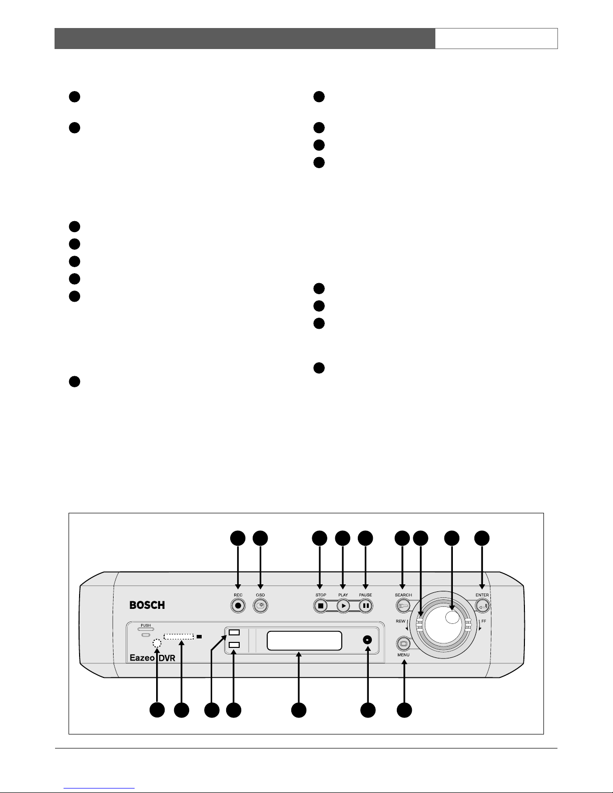
Press the Record key to start the recording immediately
- the images are recorded on the hard disk.
• The recording rate and recording quality are set in
the Normal record and Alarm record menus.
• REC (record) appears in the LCD display.
Press the Stop key to stop recording.
• Stop key can only be activated in recording mode.
• When the hard disk is full, the DVR stops recording
automatically or overwrites from the beginning of
the hard disk depending on the setting in the Normal
record menu.
3.2 Alarm recor ing
The monitor image is recorded automatically when an
alarm occurs and stops recording at the end of the alarm
duration period. Instant recording and timer recording
stop when an alarm occurs. If the unit is already
recording then the recording quality does not change for
alarm recording. Set the options for alarm recording in
the Alarm record menu.
3.2.1 Pre-alarm re ording
A 220-image buffer (for example, 9 sec. at 25 IPS or
220 sec. at 1 IPS) is used to pre-capture video for
recording images just before an alarm is triggered.
Pre-alarm recording only occurs if the unit is not already
recording during the pre-alarm period. The recording
quality in the pre-alarm period is the same as the
recording quality before the alarm occurs. If the
recorder is not recording before the alarm occurs, the
recording quality in the pre-alarm period is the same as
normal recording quality.
3.3 Normal playback
Playback
• Press PLAY key to start playing back the stored
image/audio from the last segment.
• Press STOP key to stop playing back.
Fast Forward
• Press PLAY key to start playing back.
• Turn the Shuttle Ring clockwise and fast forward
playback starts. The speed is shown on the display
(normal play speed, 2x, x, 8x, 16x, 32x, 6 0x).
Reverse Playback
• Press PLAY key to start playing back.
• Turn the Shuttle Ring counterclockwise and fast
reverse playback starts. The speed is shown on the
display (normal play speed, 2x, x, 8x, 16x, 32x,
6 0x).
Slow Forward Playback
• Press Pause key to freeze the playing back picture.
• Turn the Shuttle Ring clockwise and slow forward
playback starts. The speed is shown on the display
(>1/2, 1/ , 1/8, 1/16, 1/32, 1/6 ).
Slow Reverse Playback
• Press Pause key to freeze the playing back picture.
• Turn the Shuttle Ring counterclockwise to start slow
reverse playback. The speed is shown on the display
(<1/2, 1/ , 1/8, 1/16, 1/32, 1/6 ).
Lock displayed speed
• To lock the displayed speed, press the Enter key and
then release the Shuttle Ring. If you turn the Shuttle
Ring again, the speed returns to normal play speed
or 1/2x.
Image advance Forward/Reverse
• Press Pause key to freeze the picture.
• Turn the Jog Dial clockwise to advance the picture
image by image.
• Turn the Jog Dial counterclockwise to rewind the
picture image by image.
• The image speed increases if the Jog Dial is turned
quickly.
3.4 Search playback
Segment Search Playback
• Press the Search key to enter the Search menu.
• Move the cursor to BY SEGMENT LIST and press
the Enter key to select file search.
• Move the cursor to the segment you want to
playback (pAlarm: Pre-alarm record, Timer: Timer
record).
• If the selection list is full, turn the Jog Dial clockwise
to select the next page list.
• Press Enter to start playing back.
Alarm Search Playback
• Press Search key to enter the Search menu.
• Move the cursor to BY ALARM LIST and press the
Enter key to select alarm search.
EazeoRecorderInstal.book Page 10 Wednesday, March 3, 2004 12:23 PM

Bosch Security Systems | 2003-11
Eazeo DVR | Installation Manual | Chapter 3 EN | 11
• Move the cursor to select the alarm image to be
played back.
• If the selection list is full, turn the Jog Dial clockwise
to select the next page list.
• Press Enter to start playing back the alarm images.
• The alarm image is played back from the pre-alarm
period and stops at the end of alarm duration.
Date/Time Search Playback
• Press Search key to enter the Search menu.
• Move the cursor to BY DATE/TIME and press the
Enter key to select file search.
• Move the cursor to the value you wish to select and
press the Enter key.
• Turn the Jog Dial to increase or decrease the value
and press the Enter key.
• Move the cursor to START SEARCH AND PLAY
and press the Enter key and the playback starts from
the date/time set in the menu.
If there is no image stored in the date/time specified
then the unit automatically starts playing back from the
nearest set time.
3.5 Copy
Insert a Compact Flash card into the Compact Flash slot
on the front panel. When inserting the Compact Flash
card, make sure that the direction of insertion is correct.
Use only a Compact Flash card with a capacity of 16MB
or higher.
3.5.1 Still image opy
• Press the Play key to start playing back.
• Press the Pause key to freeze the picture.
• Turn the Jog Dial clockwise or counterclockwise to
move to the desired image.
• Press the Copy key to enter the copy mode.
• Turn the Jog Dial to select the desired camera image.
• While the image is displayed, press the Copy key
again. The message "Copying …" appears on the
screen during the process. The message "Success"
and the file identification appears on the screen after
the file is copied.
• Press the Play key to continue playback.
Copied images are stored as a single picture in a JPG
file format.
3.5.2 Copy to movie file
• Press the Play key to start playing back.
• Press the Copy key to enter the copy mode.
• Turn the Jog Dial to select the desired camera.
• While the image is displayed, press the Copy key
again. The message "Copying …" appears on the
screen during the process.
• Press STOP key to end copy.
• The message "Success" and the file identification
appears on the screen after the file is copied.
• Press the Play key to continue playback.
Copied images are stored as a movie picture in a MOV
file format.
3.6 Security lock setting
Press the Rec key for more than 5 seconds while in the
record mode to lock all the keys on the front panel.
(Password must be set in System Setting Menu to enable
this feature.)
Press Stop key, the system asks for the password. If you
enter the correct password, the locked keys are released.
EazeoRecorderInstal.book Page 11 Wednesday, March 3, 2004 12:23 PM

Bosch Security Systems | 2003-11
Eazeo DVR | Installation Manual | Chapter 4 EN | 12
4 Menu set-up
When system has been connected as described:
• Switch power on
• The display lights if power is normal.
• Allow some time for the system to load.
• Press the MENU key to enter the MAIN MENU.
When the main menu is displayed you see the different
submenus where the settings can be changed.
To navigate through these menus, turn the Jog Dial
clockwise or counterclockwise to scroll through the
submenus. Press the ENTER key to open a submenu. In
the submenus, continue using the Jog Dial and ENTER
key to scroll through items and values and select them.
To return to the main menu, scroll to the bottom of each
submenu to the MAIN MENU item and select it by
using the ENTER key.
4.1 Main menu
4.2 Clock/Language menu
DATE: Year: 2000~2099 Month: 01~12 Date: 01~31
TIME: Hour: 00~23 Minute : 00~59 Second: 00~59
DATE FO MAT: Set the display order for Year (YYYY), Month (MM)
and Day (DD)
MENU LANGUAGE: English, German, French, Spanish, Italian,
Portuguese, Dutch or Polish.
MAIN MENU: eturn to the main menu.
4.3 Normal recor menu
SPEED : Select the record speed from 0.1 to 25/30 IPS.
QUALITY: There are six quality levels for recording
LOWE 15 KB
LOW: 20 KB
BASIC: 25 KB
STANDA D: 30 KB
HIGH: 35 KB
SUPE IO : 40 KB
MULTIPLEXE :
Select Multiplexer connection or one camera connection
ON : The video input from MUX MAIN MONITO connector
at the rear panel is looped through to the MONITO OUT
when the recorder is not in MENU mode.
OFF : The main monitor output is same as video out
connector all the time.
VEXT: There are two modes for Time lapse recording, 1 FIELD (1, 2,
3, 4, 5 etc.) or 2 FIELDS of the same camera (1, 1, 2, 2, 3, 3,
4, 4, 5, 5 etc.).
DISK FULL:
STOP : When disk is full, the machine stops recording.
EW ITE : When disk is full, the current video overwrites the
existing video from the beginning of the hard disk.
4.4 Alarm recor menu
ALA M OPE ATION:
ON : ecord when alarm occurs.
OFF : Do not record when alarm occurs.
ECO D SPEED: ecording speed for the duration of the alarm.
The max. recording speed is 25/30 IPS (PAL/NTSC).
The min. recording speed is 0.1 IPS.
MAIN MENU
CLOCK/LANGUAGE >
NORMAL RECORD >
ALARM RECORD >
TIMER >
BUZZER >
ARCHIVE >
NETWORK >
SYSTEM SETTING >
CLOCK/LANGUAGE MENU
DATE 2002-04-24
TIME 13:01:02
DATE FORMAT YYYY-MM-DD
MENU LANGUAGE ENGLISH
MAIN MENU >
NORMAL RECORD MENU
RECORD SPEED 10 IPS
RECORD QUALITY STANDARD
MULTIPLEXER ON
VEXT 1 FIELD
DISK FULL REWRITE
MAIN MENU >
ALARM RECORD MENU
ALARM OPERATION ON
RECORD SPEED 25 IPS
RECORD QUALITY STANDARD
ALARM-IN TYPE N.O.
ALARM-RESET TYPE N.O.
ALARM DURATION TIME 10 SECS
PRE-ALARM OPERATION ON
RECORD SPEED 25 IPS
MAIN MENU >
EazeoRecorderInstal.book Page 12 Wednesday, March 3, 2004 12:23 PM

Bosch Security Systems | 2003-11
Eazeo DVR | Installation Manual | Chapter 4 EN | 13
ECO D QUALITY: ecording picture quality when alarm occurs.
LOWE : 15 KB
LOW: 20 KB
BASIC: 25 KB
STANDA D: 30 KB
HIGH: 35 KB
SUPE IO : 40 KB
ALA M-IN TYPE:
N.O. : Normally Open
N.C. : Normally Closed
ALA M- ESET TYPE:
N.O. : Normally Open
N.C. : Normally Closed
ALA M DU ATION TIME: Alarm recording starts from the beginning
of alarm and stops at the end of the duration or when alarm
reset is activated. The max. duration is non-stop, the min.
duration is 10 seconds.
P E-ALA M OPE ATION:
ON: ecord the picture in pre-alarm recording speed in pre-
alarm period.
OFF: No pre-alarm recording before alarm occurs.
ECO D SPEED: The recording speed in the pre-alarm period.
The max. recording speed is 25/30 IPS (PAL/NTSC).
The min. recording speed is 0.1 IPS.
Note
If the alarm occurs in standby or normal recording
mode, the recording quality is the same as the normal
recording quality. If the alarm occurs in timer recording
mode, the recording quality is the same as the value set
in timer recording quality.
4.5 Timer menu
The monitored image can be recorded automatically by
setting the start and end times in the TIMER MENU.
There are 15 entries where a recording schedule for a
particular day or set of days can be set for the week.
Move to an entry and press enter to select the day.
If you program for example the following:
START 09:00, STOP 23:59
Than recording starts at 09:00:00 and stops at 23:59:59.
WEEK: Selects the day or set of days for the timer.
DLY: every day
WDAY: Monday to Friday
WEND: Saturday and Sunday
Individual days of the week
STA T: Enter the start time for timer recording.
STOP: Enter the end time for timer recording.
STOP time needs to be later than the STA T time.
(e.g. STA T 16.00, STOP 03.00 is not correct
STA T 16.00, STOP 00.00 is not correct
STA T 16.00, STOP 23.59 is correct
SPEED: When SPEEED FO MAT set by HOU , the recording speed
can be set from 4/6 (NTSC/PAL) H to 960H .
When SPEED FO MAT set by IPS, the recording speed can
be set from 0.1~30/0.1~25(NTSC/PAL)IPS.
QUALITY: There are six recording picture quality levels
LOWE : 15 KB
LOW: 20 KB
BASIC: 25 KB
STANDA D: 30 KB
HIGH: 35 KB
SUPE IO : 40 KB
SET: Set ON when using timer recording.
Set OFF when not using timer recording.
In Timer Recording mode, the display shows the Timer
date/time and the Timer recording rate appears under
T.REC.
You cannot change the quality level for continuous
recording. For example:
Seg 1 08:30~17:00
Seg 2 17:00~23:59
Seg 1 and Seg 2 are treated as the continuous recording
08:30~23:59.
If you need to set different quality level, set as follows:
Seg 1 08:30~16:59
Seg 2 17:00~23:59
TIMER MENU
WEEK START STOP SPEED QUALITY SET
SUN 00:00 00:00 002 HR STANDARD OFF
MON 00:00 00:00 002 HR STANDARD OFF
WDAY 00:00 00:00 002 HR STANDARD OFF
WEND 00:00 00:00 002 HR STANDARD OFF
DLY 00:00 00:00 002 HR STANDARD OFF
MON 00:00 00:00 002 HR STANDARD OFF
TUE 00:00 00:00 002 HR STANDARD OFF
FRI 00:00 00:00 002 HR STANDARD OFF
THU 00:00 00:00 002 HR STANDARD OFF
WED 00:00 00:00 002 HR STANDARD OFF
SAT 00:00 00:00 002 HR STANDARD OFF
SUN 00:00 00:00 002 HR STANDARD OFF
MAIN MENU >
EazeoRecorderInstal.book Page 13 Wednesday, March 3, 2004 12:23 PM

Bosch Security Systems | 2003-11
Eazeo DVR | Installation Manual | Chapter 4 EN | 14
4.6 Buzzer menu
BUZZE OPE ATION:
ENABLE: Select buzzer to be on.
DISABLE: Select buzzer to be off.
Note: Press Enter button to enable/disable in ecord/Playback
mode.
ALA M-IN: ON - the buzzer sounds when the alarm occurs.
ECO D-IN: ON - the buzzer sounds when ecord-IN signal is
applied on the ecord-IN terminal.
DISK FULL: ON - the buzzer sounds when disk is nearly full 99.7%
VIDEO LOSS: ON - the buzzer sounds when the video signal is lost.
TIME : ON - the buzzer sounds when timer record occurs.
4.7 Archive menu
PICTU E SIZE: Select picture size for copying image to CF card
Big size: 720x576 (PAL), 720x480 (NTSC)
Small size: 352x288 (PAL), 352x240 (NTSC)
TIME STAMP:
ON: Time stamp appears on the picture when copying image
to CF card.
OFF: Time stamp does not appear on the picture when
copying image to CF card.
TIME STAMP POSITION:
BOTTOM: Time stamp appears at the bottom
TOP: Time stamp appears at the top
WATE MA K:
ON: Water mark appears on the picture when copying image
to CF card.
OFF: Water mark does not appear on the picture when
copying image to CF card.
WATE MA K POSITION:
BOTTOM: Water mark appears at the bottom
TOP: Water mark appears at the top.
4.8 Network menu
IP ADD ESS: Fill in the IP address of the unit in the network system.
NETMASK ADD ESS: Fill in the Netmask of the unit in the network
system.
GATEWAY ADD ESS: Fill in the Gateway address of the unit in the
network system.
SETUP USE : Three user names and passwords can be set up. A
setup menu is available for each of the three users.
The Eazeo DVR Login page appears on the PC screen
when you connect a PC via a network to the Eazeo
DVR. The Setup User menu allows the administrator to
set the login User name and password, and the access
level. The system has three different access levels:
• SUPER access can view live/playback video and
control Eazeo DVR operation.
• GENERAL access can view live and playback video.
• GUEST access can only view live video.
A maximum of four connections can be made at the
same time (1 user name and password shared).
BUZZER MENU
BUZZER OPERATION ENABLE
ALARM-IN ON
RECORD-IN ON
DISK FULL ON
VIDEO LOSS ON
TIMER OFF
MAIN MENU >
ARCHIVE MENU
PICTURE SIZE 720 X 576
TIME STAMP ON
TIME STAMP POSITION BOTTOM
WATER MARK ON
WATER MARK POSITITON BOTTOM
MAIN MENU >
NETWORK MENU
IP ADDRESS 192.168.010.005
NETMASK ADDRESS 255.255.255.000
GATEWAY ADDRESS 000.000.000.000
SETUP USER 1 >
SETUP USER 2 >
SETUP USER 3 >
MAIN MENU >
SETUP USER 1
USER NAME ADMIN _ _ _
USER PASSWORD ADMIN _ _ _
USER LEVEL SUPER
NETWORK MENU >
MAIN MENU >
EazeoRecorderInstal.book Page 14 Wednesday, March 3, 2004 12:23 PM

Bosch Security Systems | 2003-11
Eazeo DVR | Installation Manual | Chapter 4 EN | 15
4.9 System setting menu
PASSWO D ENABLE:
YES: PASSWO D required to enter the menu.
NO: PASSWO D not required to enter the menu.
PASSWO D :
When YES is set for PASSWO D ENABLE, a password is
required to enter the menu. The code is six digits long and
can be any digit from 1 to 5.
If you have activated the password, whenever you press the
menu button in live mode or stop button in record mode the
system asks you to enter the password. Therefore, be sure to
make a note of the password.
VIDEO INPUT:
COMPOSITE: Select the video input from BNC connector
(setting for Eazeo).
S-VIDEO: Select the S-VIDEO from S-VIDEO connector.
PLAY WITH AUDIO 1 / PLAY WITH AUDIO 2:
ON/OFF: Playback with or without audio.
Audio recording and playback is only possible in realtime
mode with a speed of 1IPS or higher. (Playback at the same
rate you record.)
SPEED FO MAT: Select recording speed by IPS (Images per
second) or Hour
VIDEO SYSTEM: Select the video system NTSC or PAL (requires
power reset to activate).
DISK ENEW:
Press Enter to erase or not to erase HDD.
The confirmation dialog box appears on the screen.
Select Yes or No and then press ENTE .
SYSTEM UPDATE:
Press Enter to update the system or not.
YES: Copy the update file onto the Compact Flash card on
the PC and then insert the Compact Flash card into the slot.
Press ENTE key to update the system. After the system is
updated successfully, be sure to reset the power to activate.
LOAD DEFAULT:
Press Enter to load the factory default or not.
YES: The confirmation dialog box appears on the screen.
Select Yes or No and then press ENTE .
CF ENEW:
YES: will format the Compact Flash card.
NO: will not format the Compact Flash card.
4.10 Passwor menu
When password protection is enabled, a password menu
appears on the screen when you try to open a menu or
stop recording. You must enter the password using the
following keys:
REC : 1
OSD : 2
STOP : 3
PLAY :
PAUSE : 5
SYSTEM SETTING MENU
PASSWORD ENABLE NO
PASSWORD 555555
VIDEO INPUT COMPOSITE
PLAY WITH AUDIO 1 ON
PLAY WITH AUDIO 2 ON
SPEED FORMAT BY IPS
VIDEO SYSTEM PAL
DISK RENEW >
SYSTEM UPDATE >
LOAD DEFAULT >
CF RENEW >
MAIN MENU >
EazeoRecorderInstal.book Page 15 Wednesday, March 3, 2004 12:23 PM

Bosch Security Systems | 2003-11
Eazeo DVR | Installation Manual | Chapter 5 EN | 16
5 View via Internet/Intranet
5.1 Login
Open your internet browser and enter the network IP
address (for example, http://192.168.10.5). This must be
the same IP address as set in the Eazeo DVR Network
Menu.
The Eazeo DVR Login page appears on the screen. You
must enter the correct user-name and password as are
set in the Eazeo DVR Network Menu. (As default, enter
ADMIN for user name and ADMIN for password and
then click on Submit to enter to system.)
5.2 Main Screen
The three icons at the bottom of the screen are for
switching to the Live mode, the Playback mode or for
logging out. Information regarding the status of the
system is also shown at the bottom of the screen. The
present system status and the date and time are shown.
The icons on the right select the cameras and determine
how these are displayed on the screen. Playback
controls are also located on the right. The search
function allows you to select a clip for playback. If an
icon is shaded, it means that the specific function is not
accessible in the current mode.
Note
Update rate of LIVE images is dependent on the
selected recording speed when the unit is in Record (e.g.
recording in 0.5 IPS will give an update of 2 seconds per
camera image.
It is not possible to display LIVE images when the
recorder is in playback. The system status will indicate
“SERVER IN PLAYBACK”
EazeoRecorderInstal.book Page 16 Wednesday, March 3, 2004 12:23 PM

Bosch Security Systems | 2003-11
Eazeo DVR | Installation Manual | Chapter 5 EN | 17
5.2.1 Playba k mode i ons
• STOP: Press this key to stop video display.
• PLAY: Playing back the video display.
• REV. PLAY: Reverse video display.
• Step Forward the video display.
• Step Backward the video display.
• PAUSE: Press this key to pause the video display.
• CONTROL: Press this key to switch to direct remote
control mode (only allowed with access level
SUPER). You can now start or stop playback and
recording remotely.
• Control for playback speed.
• Control for playback position by search feature.
5.2.2 Live mode i ons
Only the camera icons and the camera view icons are
enabled in the view mode.
5.2.3 Sear h i ons
The system gives you three ways to select video for
playing:
• Play video selected by segment list.
• Play video selected by alarm list.
• Play video selected by date/time.
An item shown in the list can be selected by a mouse
click. Click PLAY to play the selected video.
EazeoRecorderInstal.book Page 17 Wednesday, March 3, 2004 12:23 PM

Bosch Security Systems | 2003-11
Eazeo DVR | Installation Manual | Chapter 6 EN | 18
6Specifications
6.1 RS-232 interface
The Eazeo DVR can be controlled by a computer or a
terminal via the standard D-SUB 9-pin RS-232
connector.
The transmission setting is 9600 baud rate, 8 data bits, 1
start bit, 1stop bit and no parity.
6.1.1 RS-232 ontrol proto ol
A computer or a terminal can be used to control the unit
by sending three character ASCII commands through
the RS232 connector, these ASCII commands are
started with 'K' or 'k'. There are 30 ASCII commands
mapped to the 30 keypads in the front panel. The 30
ASCII commands are shown on the following table.
Pin Pin
Eazeo HOST
1NC 1 NC
2 TXD 2 RXD
3 RXD 3 TXD
4 NC 4 DTR
5 GROUND 5 GROUND
6 NC 6 DSR
7 NC 7 RTS
8 NC 8 CTS
9 +5V 9 NC
ASCII
CODE
FUNCTION Keypad in
front panel
K01 Start Recording REC
K03 Stop Recording and
Playing back
STOP
K04 Playing back PLAY
K05 Pause the playback
picture
PAUSE
K06 Search playback SEARCH
K00 Copy picture into
CF card
COPY
K02 On screen display DISPLAY
K07 Confirm the
selection
ENTER
K08 Enter Setting Menu MENU
K09-
K15
Fast reverse
playback speed
<< 1-640 X,
1/2-1/64
K16 -
K22
Fast playback speed >> 1-640 X,
1/2-1/64
K23 Rewind the still
image
JOG-REW
K24 Advance the still
image
JOG-FF
EazeoRecorderInstal.book Page 18 Wednesday, March 3, 2004 12:23 PM

Bosch Security Systems | 2003-11
Eazeo DVR | Installation Manual | Chapter 6 EN | 19
6.2 Recor ing time
Approximate recording times when recording with a
160-GB hard disk.
Reference:
2 H=1 day, 168H=1 week, 720H=1 month,
8760H=1year
(Estimated with typical image-low noise level)
Lower: 15 KB
Low: 20 KB
Basic: 25 KB
Standard: 30 KB
High: 35 KB
Superior: 0 KB
PAL
Recording
Rate (IPS)
Recording
Speed (Hours) Picture Quality
Lower Low Basic Standard High Superior
25 6 119 89 71 59 51 44
16 18 185 139 111 93 79 69
10 30 296 222 178 148 127 111
548 593 444 356 296 254 222
2 72 1481 1111 889 741 635 556
1.5 120 1975 1481 1185 988 847 741
1.0 168 2963 2222 1778 1481 1270 1111
0.5 240 5926 4444 3556 2963 2540 2222
0.2 480 14815 11111 8889 7407 6349 5556
0.1 960 29630 22222 17778 14815 12698 11111
Average File size 15KB 20KB 25KB 30KB 35KB 40KB
NTSC
Recording
Rate (IPS)
Recording
Speed (Hours) Picture Quality
Lower Low Basic Standard High Superior
30 6 99 74 59 49 42 37
20 18 148 111 89 74 63 56
10 30 296 222 178 148 127 111
548 593 444 356 296 254 222
2 72 1481 1111 889 741 635 556
1.5 120 1975 1481 1185 988 847 741
1.0 168 2963 2222 1778 1481 1270 1111
0.5 240 5926 4444 3556 2963 2540 2222
0.2 480 14815 11111 8889 7407 6349 5556
0.1 960 29630 22222 17778 14815 12698 11111
Average File size 15KB 20KB 25KB 30KB 35KB 40KB
EazeoRecorderInstal.book Page 19 Wednesday, March 3, 2004 12:23 PM

Bosch Security Systems | 2003-11
Eazeo DVR | Installation Manual | Chapter 6 EN | 20
6.3 Technical specifications
Vi eo
Format PAL/NTSC
Input 1 camera input (BNC), 1Vpp,
75Ohm
Output 1 video output (BNC) for main
monitor, 1Vpp, 75Ohm
Compression M-JPEG
Resolution 720 x 576 (PAL) /
720 x 484 (NTSC)
Display Full display for live and playback
Au io
Connections 2 mono inputs, 1.6Vpp
±200mV@10K
2 mono outputs, 1.6Vpp
±200mV@10K
Alarm
Input Switching voltage High: > 2 Vdc
Switching voltage Low: < 0.5 Vdc
Output One relay output:
Contact voltage max.: 24 Vdc
Switching current max.: 2A dc
Storage
Hard disk 160 Gb
Recor ing
Mode Continuous, time-lapse, schedule or
event recording
Rate Max. 25 images per sec. (PAL)
Max. 30 images per sec. (NTSC)
Playback
Rate Max. 25 images per sec. (PAL)
Max. 30 images per sec. (NTSC)
Search Date/time, segment list or event
(alarm)
General
Video loss detection Yes
Power loss detectionYes
Alarm log Yes
User interface Menu-driven
Setup By on-screen display menu
User input device Front panel keypad, remote control
(IR with wired receiver) optional
Image export Built-in Compact Flash slot
Security Password protection
Power supply 100 - 240 Vac, 50/60 Hz
Power consumption < 40 W
Timer Weekly timer, built-in real time clock
Network connection 10Base-T, TCP/IP via Ethernet,
RJ-45 connector
Control connection RS-232, 9-pin D-Sub connector
Mechanical
Weight approx. 5.5 kg / 11.5 lbs
Dimensions (WxHxD)346 x 88 x 269 mm
13.6 x 3.5 x 10.5 inches
Ambient temperature
Operating +0°C … +50°C
+32°F . . . +122°F
Approvals
Safety
Europe EN60950
USA UL60950 UL & cUL listed
Australia C-Tick
Electro Magnetic Compatibility (EMC)
Europe EN55022 Class B, EN50130-4
USA FCC part 15, class B
Australia AS/NZS 3548
Specifications may change without notice. If you have
any problems, contact your dealer.
EazeoRecorderInstal.book Page 20 Wednesday, March 3, 2004 12:23 PM

Bosch Security Systems | 2003-11
Eazeo DVR | Installation Manual | Chapter 6 EN | 21
EazeoRecorderInstal.book Page 21 Wednesday, March 3, 2004 12:23 PM
Table of contents
Other Bosch DVR manuals

Bosch
Bosch DIVAR AN 5000 User manual

Bosch
Bosch DIVAR AN 5000 User manual

Bosch
Bosch DIVAR AN 3000 User manual

Bosch
Bosch 600 Series Instructions for use

Bosch
Bosch DESAXL User manual

Bosch
Bosch DIVAR 2000 User manual

Bosch
Bosch PowerPack 400 User manual

Bosch
Bosch DVR1A1081 User manual

Bosch
Bosch DIVAR IP 7000 User manual

Bosch
Bosch DVR 670 Series Instructions for use

Bosch
Bosch RS-232 User manual

Bosch
Bosch DVR4C1161 User manual

Bosch
Bosch DVR 630/650 User manual

Bosch
Bosch Divar 700 Series User manual

Bosch
Bosch DVR 670 Series User manual

Bosch
Bosch Divar 700 Series User manual

Bosch
Bosch DVR1A1081 User manual

Bosch
Bosch DVR-3000 User manual

Bosch
Bosch DVR1A Series User manual

Bosch
Bosch DIVAR AN 3000 How to use