IPM BalancedPower II-S 15 kVA User manual

OPERATIONS AND
MAINTENANCE MANUAL
for
International Power Machines®
BalancedPower II-S
15 kVA
18 kVA
20 kVA
164201020 Rev A
Uninterruptible Power System
(UPS)
SAVE THESE IMPORTANT
SAFETY INSTRUCTIONS
This manual contains important safety instructions
that should be followed during installation and
maintenance of the UPS and Battery Cabinets.
International Power Machines®
10451 Brockwood Road
Dallas, Texas 75238-1641
Phone: (214) 342-6100
Service Hotline (800) 777-8922

How To Use This Manual
Aproper understanding and use of this operating and maintenance manual will enhance UPS
system reliability. Therefore, the manual should be given equal status with the tools and equip-
mentusedtoalignandmaintainthesystem. Conversely,improperunderstandingorapplication
oftheprinciplessetforthcanresultinimpairedsystemoperation,lossofpowertocriticalequip-
ment loads, injury to personnel and/or damage to the UPS.
The following guidelines will assist in the understanding and use of this manual.
1.Become familiar with the Table of Contents. It is here that the user
can first determine where in the manual required information or
guidance can be found.
2.Read through the entire manual so as to become familiar with its style
and general contents.
3. Know the manual’s limitations. It is not the intent of this manual to
give a detailed theory of operation of the UPS. Troubleshooting is
limited to the isolation and correction of problems that are signaled by
the Control/Monitoring/Alarm Panel.
4. Be thoroughly familiar with the safety precautions outlined in Sections
II and IV of the manual.
5. Do not take shortcuts when operating the UPS or performing
maintenance on the system. A slower, more deliberate pace will give
better results because it eliminates confusion and any false conclusions
which may be reached by skipping steps. Careful adherence to step
sequences presented herein is, more often than not, the fastest way to
achieve desired results.
6. This manual is written based on the assumption that maintenance
personnel will be fully knowledgeable in electronics and aware of the
hazards of working with high voltage equipment. Always remember
that voltages may be present even when the system has been fully shut
down.Use a voltmeter to check terminals to ground. There is no
substitute for common sense.
7.Don’t guess. If you don’t know, ask someone who does.
8.Remember that the International Power Machines Service Staff is
always available to answer your questions or provide helpful advice
about your UPS. Call them on our Service Hot Line:
Telephone: (800) 777–8922
Outside U.S.: (214) 272–8000

IPM at your service
International Power Machines Corporation considers prompt customer
service to be an integral part of its product. Our Field Service Department
is accessible by telephone 24 hours a day, seven days a week to
implement timely servicing of our equipment.
IPM 24-HOUR SERVICE HOTLINE:
Phone: (800) 777-8922
Outside U.S.: (919) 871-1800
Fax: (214) 342-6115
When calling for service assistance, have the following
information and record of readings and alarm lights from
the machine's monitor panel available for the IPM service
dispatcher.
Serial Number: (On lable inside machine's front door)
Input Output
Voltage
Frequency (Hz)
Model No. Monitor
10451 Brockwood Rd, Dallas, Texas 75238-1641, U.S.A.
(214) 342-6100
InternationalPower Machines

Important Notice
The manufacturer recommends that the
monitor panel be inspected visually every eight
hour shift to see that lights are operating and no
alarm conditions exist. If any unusual
conditions exist, call facility maintenance
personnel or IPM/LorTec Service Hotline:
(800) 777-8922

Handling and Unpacking Instructions
BPII
Handling Instructions:
1. Cabinets should always be stored in an upright position. Failure to observe this
precaution can cause serious damage and cancellation of warranty.
2. Cabinets should be forklifted only at appropriate lifting points. Make sure that forks
are long enough to go entirely under the unit and protrude from the other side. Be
careful not to puncture another unit beyond the one being lifted.
3. Chains, cables, ropes or other retaining devices should not be wrapped around a
cabinet. The weight of the system is great enough to cause collapse of the cabinet
when lifted by these means.
4. Padding must be used when transporting the system so as to help prevent damage
to the cabinets.
Inspection and Unpacking Instructions:
Receiving/Unpacking/Inspection Checklist
5. Each palletized unit is designed for forklift or liftgate handling. It is recommended
that all packaging be left intact until the unit is in close proximity to its final location
to prevent incidental damage during movement.
6. Inspect the exterior packaging for obvious damage such as punctures or gashes
that are indicative of damage to the unit. If evidence of damage exists, save the
packaging material for inspection by the carrier when a claim is filed. Request for
inspection should be made immediately.
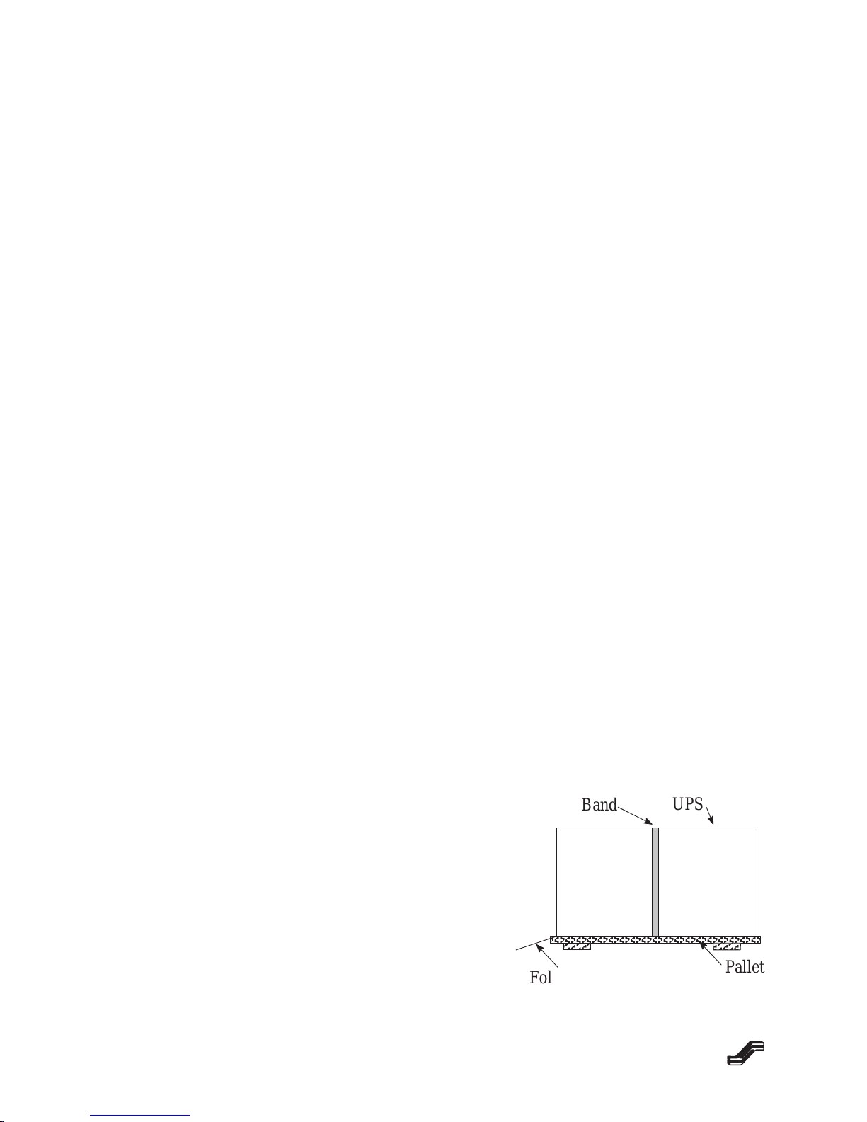
7. Strapping should be cut and the corrugated cap and/or sleeve carefully removed.
Remove padding and plastic sheeting. The cabinet then may be unbolted from the
shipping pallet.
8. Inspect each cabinet: check all exterior surfaces for scratches, chips, cracks and/or
indentations. Check monitoring panels carefully.
9. Open each door, checking for damage.
10. AlabelontheoutsideoftheUPStellsthelocationoftheOperation & Maintenance
(O & M) Manuals.
11. Remove any internal padding/packaging, checking carefully for parts, documents,
etc., that might have been shipped inside the cabinet. If foam blocks are inside the
battery trays, leave them in place. They are to keep small batteries from moving
around inside the trays.
Damage Documentation:
Itistheresponsibilityoftherecipienttofileaclaimwiththecarrierfordamagestotheequipment
or notify IPM, depending on the F.O.B. point. Any and all damage noted upon receipt of the
UPS,battery pack and/or PDU shouldbeclearly identified in detail ontheBill of Lading. Carri-
er’s claim procedures should be initiated promptly. In the event damage is found after delivery,
itshould bereportedas soonas possible(normally,thereisa 15day time limiton reportingdam-
ages incurred in shipment).
Additional information may be obtained by contacting:
Manager, Quality Assurance Phone: (800) 527–1208
International Power Machines Fax: (214) 494–2690
2975 Miller Park North
Garland, TX 75042

Page 1.1
BP
II S
, 3.00
08/96
Section I
Theory of Operation
1.1 General
The BalancedPower II–S (BPII–S) Uninterruptible Power System (UPS) presented
in this manual is a solid state, online system designed to provide high quality, continuously
filtered and conditioned ac power to computers, their peripherals and/or other critical
equipment loads. Most commonly, the UPS is configured as a single, stand-alone unit.
Three (3) power ratings are available: 15, 18 and 20 kVA. Information contained herein is
applicable to all power ratings except where specified otherwise.
A single UPS is comprised of the following basic components:
Input transformer*
Rectifier/Charger
Inverter
Static Bypass Switch
Bypass Breaker
System Control Logic and Circuitry
Digital Monitoring Panel
DC Circuit Breaker
Batteries
* Input transformer is optional for 208–220 vac input voltages and required for 240–600 vac
inputs.
A one-line diagram in Section II shows the relationship of these various components.
1.2 Rectifier/Charger
The UPS input voltage from the utility is fed into the rectifier/charger (usually
referred to as the rectifier) which converts the ac to filtered, regulated rectifier dc link
voltage. The dc is used to power the inverter and to recharge the batteries as necessary. The
assembly consists of an input circuit breaker and a solid-state three-phase rectifier designed
to eliminate even ordered harmonics. An optional input filter reduces harmonics caused by
rectifier switching, preventing the harmonics from affecting utility distribution.
1.3 Inverter
The inverter section first uses a dc booster to increase the rectifier dc link voltage to a
dc booster link voltage.

Section I
Theory of Operation
Page 1.2
BP
II
S, 3.00
08/96
The inverter then changes dc booster link voltage to precision ac voltage through
pulse width modulation (PWM) inversion. An output filter and Software Harmonic
Conditioneralgorithm provide “clean”, computer grade ac which is then sent to the critical
load. When utility power is available, the rectifier supplies power to the inverter. Should the
utility power fail, the inverter is powered by the batteries for a predetermined length of time.
1.4 Static Bypass Switch
The static bypass switch connects the UPS input to the load in the event of the loss of
the inverter output or an overload condition. During normal conditions, the static bypass
switch is in the open or disconnected mode which isolates the bypass input from the load.
If the inverter output becomes unavailable or exceeds its specified tolerance, the
static bypass switch will close and transfer the load directly to bypass ac power without
interruption. This transfer is automatically inhibited in the event the UPS bypass input is not
within specified tolerance.
As soon as the inverter becomes available, returns to within tolerance or the overload
clears, the static bypass switch will disconnect and transfer the load to the inverter. Note,
however, that so long as the inverter is out of specification, the static bypass switch will
automatically inhibit retransfer of the load.
1.5 Batteries
The 15 batteries contained in the UPS cabinet supply 180 volts dc nominal. They are
the energy reservoir of the UPS and provide dc power to the inverter in case of loss of UPS
input power or rectifier malfunction. The Battery Circuit Breaker electrically isolates the
batteries from the UPS module for maintenance purposes and provides overcurrent
protection at the battery output.
The rectifier/charger normally provides a “float” charge to the batteries. Following
periods of discharge when the batteries have supplied power to the inverter, the
rectifier/charger increases power to the batteries to recharge them. This increased voltage
level is provided until the battery charging current decreases to a preset level. At that point
the rectifier returns to a float charge.
1.6 Control Logic and Control Circuitry
The software upgradable Digital Signal Processor control logic of the UPS provides
the operating and system control for all functions ranging from limiting the inrush current by
“walking” it in, to maintaining the output voltage within rigid specifications, to determining
whether or not the static bypass switch should be activated. The control logic is, for all
practical purposes, the brain of the UPS.

Section I
Theory of Operation
Page 1.3
BP
II S
, 3.00
08/96
1.7 Digital Monitoring Panel
The UPS is equipped with a standard Digital Monitoring Panel which selectively
monitors critical parameters of the UPS, using easy-to-read digital displays. In addition,
detailed instructions guide the operator through the UPS startup. An alarm history can be
called up on these digital displays when desired.
In the event of an abnormal condition, an audible alarm sounds and the LED
illuminates red to identify an alarm condition so that corrective action can be taken. Alarm
Silence and Emergency Power Off pushbuttons are provided.
This panel is discussed in greater detail in Section III.
1.8 Multi-Level Passwords
A password is required to access and make use of the UPS Maintenance Menu,
described in Section 3.6.3. This menu, with five subsections, makes possible the
performance of a variety of maintenance functions including transfer and retransfer to
bypass, password changes and adjustment of time and date.
All passwords may be changed by a person who already knows either the password in
question or a higher level password.
Passwords consist of a minimum of 4 characters and a maximum of 9 characters.
The numerals 0 through 9 and letters A through F may be employed.
The first character of the password indicates the privilege level of the password. The
higher the privilege level, the more capabilities that password can access.
Privilege level 0: No password. Used for the front panel display of voltages, currents,
etc. only. Does not permit any menus to be accessed.
Privilege level 1: Reserved for future development.
Privilege level 2: Remote operator password. Used to monitor the UPS, but not to affect
transfers and retransfers.
Privilege level 3: Reserved for future development.
Privilege level 4: Operator password. Monitors the UPS as well as allowing transfers,
retransfers, transfer enables, retransfer enables, reset faults, etc.
Privilege level 5: Reserved.
Privilege level 6: Super-Operator password. Allows access to UPS operating
parameters. It is enabled only for users who attend a one week
maintenance training course.

Section I
Theory of Operation
Page 1.4
BP
II
S, 3.00
08/96
1.9 Phone Home Alarm Reporting
When this UPS is activated for phone home operation and the UPS senses one of
several preselected alarm conditions, the UPS automatically dials IPM’s Field Service or
another designated computer without human assistance and notifies service personnel of a
system problem requiring attention.
Important information downloaded during each phone home event includes:
1) UPS name, ID, phone number and serial number
2) customer ID and phone number
3) list of active alarms.
You obtain the following benefits from this feature:
0. a. Immediate service personnel notification of site power or UPS problems, even
when the UPS is unattended.
b. Increased availability due to reduced mean-time-to-repair with automatic
notification and complete remote diagnostic capabilities.
c. 24 hours per day, 7 days per week monitoring of unmanned facilities and
locations where operators are unfamiliar with the UPS. Often, service personnel
can take steps to solve a UPS problem remotely before the user is aware that there
is a problem.
An internal modem and a dedicated telephone line are required. Phone Home Alarm
Reporting can be activated only with a Field Service level of password. It is normally done
at the time of startup by a Customer Engineer.
1.10 Dial-Back Security
This security feature is provided to insure system integrity. It prevents “hackers” or
other unauthorized persons from intentionally or unintentionally accessing the UPS database.
Anyone calling the UPS must establish authority through the use of a dial-back password.
The unit will validate this password against up to four passwords stored in nonvolatile
memory. One of the passwords allows direct communication to commence with the UPS.
The other three passwords have associated telephone numbers. If one of these three
passwords receives validation, the UPS logic will hang up and dial back the phone number
associated with that password. When the connection is made, the remote operator must enter
the normal privilege level password for access to the corresponding level of monitoring
diagnostics and controls. In this way high level security is provided because the remote
operator must know the dial-back and access passwords and be calling from the proper
associated phone number.
An internal modem and a dedicated telephone line are required. Dial-Back Security can be
activated only with a Field Service level of password. It is normally done at the time of
startup by a Customer Engineer.

Page 2.1
BP
II S
, 3.00
08/96
Section II
Installation
2.1 General
Your International Power Machines BalancedPower II–S (BPII–S) UPS is UL–listed
and designed for installation on the computer room floor. Its attractive computer-like
appearance and quiet operation eliminate any necessity of creating special facilities to house
the UPS. Since all modern computer rooms utilize environmentally controlled conditions,
installation in such a locale will normally suffice to meet the needs of the UPS.
In the event that computer room installation is not practical, the selection of a
location for the UPS is critical to the performance of the system and to the life expectancy of
its components. Failure to select a site which meets all requirements specified in this section
can result in excessive maintenance problems.
Operating temperature range for batteries is 0C to 40C (32F to 104F). Battery
warranty is conditional upon application at or below 25C (75F). Continuous operation
above 25C may reduce or void battery warranty.
2.2 Mechanical Preparation of UPS
The UPS can be fully accessed from the front, top and left side for operation and
maintenance. Rear access is required for installation.
The following steps should be taken, in the order indicated:
1. Insure that all packing is removed from
the UPS.
2. The UPS can be rolled off the shipping
pallet by removing the support block at
the rear of the unit and using the plywood
backing as a ramp.
Figure 2–1.
ÂÂÂÂÂÂÂÂÂÂ
ÂÂÂ
ÂÂÂ
Band UPS
Pallet
Fold Down Ramp

Section II
Installation
Page 2.2
BP
II
S, 3.00
08/96
3. Remove the screws holding the panel to expose the terminals at the rear of the
cabinet. Knockouts can be made in this cover for input/output conduit
connections. For ease of installation, input/output connections can be made with
flexible conduit. This will enable the UPS to be rolled back toward a wall,
reducing floor space requirements.
4. The UPS cabinet can now be rolled on its casters to its final destination. When it
is in that location, tightening the locking bolt on each caster will hold the unit in
place.
NOTE: For proper ventilation and maintenance access, a clear area three (3′)
feet (91.4 cm) on the left side, six (6″) inches (15.2 cm) on the right side
and one (1′) foot (30.5 cm) at the rear is recommended.
5. Remove the top and left side panels to expose the batteries in the lower sections.
The top is removed by unscrewing the three screws at the upper rear of the
cabinet. Slide the top toward the rear while lifting it. The upper left side panel is
removed by sliding up from the locking bracket. The lower side panel then can
be removed by unscrewing the three screws along the top of the panel and sliding
it up from the locking bracket. If foam blocks are inside the battery trays, leave
them in place. They are to keep small batteries from moving around inside the
trays.
0.
The battery trays are shipped bolted to the shelf supports and should be left fastened
down.

Section II
Installation
Page 2.3
BP
II S
, 3.00
08/96
2.3 AC Power Connection
1. Make sure that all switches/circuit breakers, including the Battery Circuit
Breaker, are open.
WARNING
Verify that power cabling is de-energized before proceeding.
2. All power connections to the UPS terminal blocks must be torqued in accordance
with the table below.
TIGHTENING TORQUE FOR PRESSURE WIRE CONNECTORS
Size of Wire Used Torque Specification
AWG/kcmil (mm2) in-lb (N–m)
6–4 (13.3–21.2) 110 (12.4)
3 (26.7) 150 (16.9)
2 (33.6) 150 (16.9)
1 (42.4) 150 (16.9)
1/0–2/0 (53.5–67.4) 180 (20.3)
3. Referring to the installation drawings in this section, connect UPS output
terminals to the equipment to be protected, running the cables out through the
conduit holes or access plate.
4. Run cables for UPS input through the conduit holes and connect to terminal block
as shown in installation drawings in this section. See notes on installation
drawings for single input or dual input installations.
5. Replace the panel over the terminal block.

Section II
Installation
Page 2.4
BP
II
S, 3.00
08/96
2.4 Activating the Batteries
Make sure that all packing material has been removed from the battery section. If
foam blocks are inside the battery trays, leave them in place. They are to keep small
batteries from moving around inside the trays.
0. 1. Connect the batteries as shown in Figure 2–2. The two connectors (red and
black) are connected together to provide the final connection for the battery
system.
2. Replace the side panels and top of the UPS cabinet.
The uninterruptible power system is now ready for startup. See Section III,
Operation.
WARNING
Do not close the battery circuit breaker until instructed to
do so in the startup procedure.

Section II
Installation
Page 2.5
BP
II S
, 3.00
08/96
BATTERY A4 TO CB3–CC
BATTERY A3
BATTERY A2
BATTERY A1 TO CB3–BB
RED
BLK
4 Battery Trays
Figure 2–2. Battery Interconnection Diagram

Section II
Installation
Page 2.6
BP
II
S, 3.00
08/96
This Page Intentionally Left Blank.

Page 3.1
BP
II S
, 3.00
08/96
Section III
Operation
3.1 General
This section contains safety considerations, UPS operational procedures, and an
overview of the monitoring panel and operating controls for the system. Prior to operation,
ensure that the UPS has been installed correctly as outlined in Section II of this manual.
Ensure that correct input/output phase rotation and battery polarities have been observed.
Failure to do so can result in damage to the UPS and/or injury to personnel. Operators
should be thoroughly familiar with the contents of this manual and with the location and
function of all system controls and indicators.
3.2 Safety Considerations
Safety considerations are divided into several areas which are discussed below. Refer
also to Section IV of this manual, Maintenance, for safety precautions to be taken whenever
operating or working on the UPS.
3.2.1 Cleanliness
Litter or trash of any sort should not be allowed to accumulate in or around the UPS.
Liquid spills or metal objects carelessly dropped or placed can cause shorts and damage to
the system as well as possible injury to personnel. Dirt and dust accumulating at the UPS air
inputs can impede air flow, thereby decreasing the cooling effectiveness of the blowers and
possibly resulting in an overtemperature shutdown of the system.
3.2.2 Fire
In order to minimize the possibility of a fire and to reduce the extent of any damage
resulting from such an incident, the walls, ceiling and floor of the UPS room should be
constructed of noncombustible materials. A portable carbon dioxide extinguisher should be
located in the UPS room. Personnel involved in operating and/or maintaining the UPS
should be familiar with Class C hazard fires.

Section III
Operation
Page 3.2
BP
II
S, 3.00
08/96
3.2.3 Security/Personnel
Access to the UPS should be limited to a minimum of personnel. All personnel who
operate or maintain the UPS should be proficient in normal and emergency operational
procedures. A refresher briefing or test at specific intervals is recommended to maintain this
proficiency. New personnel should be trained and tested prior to operating the equipment. A
thorough knowledge of first aid procedures, especially those pertaining to electrical shock or
burns, and the use of carbon dioxide fire extinguishers should be mandatory.
3.3 Radio Frequency Energy Hazard
WARNING
This equipment generates, uses and can radiate radio frequency
and if not installed and used in accordance with instructions may
cause interference to radio communications. It has been
designed to comply with the limits for Class A computing devices
pursuant to Subpart J, Part 15 of FCC Rules, which are intended
to provide reasonable protection against such interference when
operated in a commercial environment. Operation of this
equipment in a residential area is likely to cause interference in
which case the user at his own expense will be required to take
whatever measures may be necessary to correct such
interference.
Always be aware that hazardous voltages may be present within
the UPS even when the system is not operating.

Section III
Operation
Page 3.3
BP
II S
, 3.00
08/96
3.4 Digital Monitoring Panel
The UPS Digital Monitor Panel consists of a multicolor LED Status Indicator Light,
an LCD message screen, two Menu (Display Select) pushbuttons, three (3) Parameter Adjust
pushbuttons and an ALARM SILENCE pushbutton. The Menu buttons provide access to the
various data and messages which are displayed on the Message Screen. These include
detailed instructions for startup sequence, alarm parameters, available battery run time and
alarm conditions. An EMERGENCY POWER OFF (EPO) pushbutton is located in the upper
left corner of the front panel.
MESSAGE SCREEN
ALARM SILENCE
Figure 3–1. Digital Monitoring Panel

Section III
Operation
Page 3.4
BP
II
S, 3.00
08/96
3.4.1 Indicator Light
If the multicolor indicator light (LED), located in the upper part of the panel, is:
•Green: UPS Normal – This indicates that the critical load is being powered from
the inverter. It represents a fully normal condition. With any alarm the LED will
change color to indicate a noncritical or actual alarm. When the alarm condition
is corrected, the LED will turn green again. See Paragraph 3.4.5 for more details.
•Green/Red: NonCritical Alarm – This indicates that a noncritical alarm is
present, and that message will appear on the message screen. Check Alarm
History (Paragraph 3.4.2.2) to identify the alarm.
•Red: Alarm Condition – When the LED turns red, a problem exists with the
UPS. Alarms such as ac input failure, low battery voltage, UPS overload,
transferred to bypass, transfer not available, battery not available and/or
retransfer inhibited may exist. Check active alarm conditions (Paragraph 3.4.2.1)
or alarm history (Paragraph 3.4.2.2) to identify the alarm.
–AC Input Failure – The UPS input power has been disrupted or gone out of
specification limits. The system goes to battery power and the alarm sounds,
alerting the operator to a brownout or power failure. When the batteries run
down, the critical load will shut off unless steps are taken to correct the
situation or another source of input power is provided.
–Low Battery Voltage – When the system is operating on battery power, this
condition indicates approximately five minutes remains before the UPS
system shuts down. A message screen (Section 3.4.2) displays the amount of
battery run time left. Also, the rectifier link (battery) voltage may be
monitored (See Paragraph 3.4.2.8). Shutdown occurs when the link voltage
drops to 148.5 VDC (selectable). If utility power can not be restored or an
auxiliary power source be activated, the critical load should be shut down in
an orderly procedure.
–UPS Overload – The load on the UPS output is in excess of 105% of rated
load. If the condition exists for more than a few seconds, enough of the
critical load should be powered down or removed to make the indicator go
green. Otherwise, the UPS will shut down and/or transfer to bypass within 15
minutes.
This condition may occur when the UPS is loaded close to 100% and a large
disk drive or other motor load is started. These loads draw currents many
times their normal level for a few seconds when first started. The UPS is
designed to handle this short overload condition.

Section III
Operation
Page 3.5
BP
II S
, 3.00
08/96
–Transferred to Bypass – An indication that the critical load is being powered
directly from the UPS bypass power source. This situation is created when
maintenance personnel want to bypass the UPS through the static bypass
switch for routine maintenance or when an abnormal condition exists in the
inverter, such as failure or extended overload. When in this operational mode,
the critical load does not have UPS protection.
–Transfer Not Available – An indication that transfer to the static bypass
switch is not possible. This may be caused by the UPS bypass input power
source being out of specification or a power outage.
–Battery Not Available – The battery’s DC Disconnect (circuit breaker) is
open or a battery cabinet fuse is blown. The battery is not available to power
the inverter if needed.
–Retransfer Inhibited – An indication that the inverter is out of specification
or has lost phase lock with the bypass power source. When active in
conjunction with the Transferred to Bypass indicator, power cannot be
retransferred from the static bypass switch back to the inverter.
3.4.2 Message Screens
Message screens display the status of the UPS. To scroll through these screens,
depress or buttons.
Following are the legends that appear in this
area while the UPS is running normally. To display
these in this order, start with the screen at right and
depress the button to show each screen in turn.
If the UPS is operating on battery power,
this screen will appear instead. It can be monitored
to determine the battery run time remaining during
a power outage.
3.4.2.1 Active Alarm Condition
If any active UPS alarm conditions exist, the
condition(s) will be shown on this screen. When
NONE is indicated, no alarm conditions are active.
With activation of alarm condition(s), one or more
of the following abbreviations will be displayed:
UPS
Operating Normally
Time Left XXX Min
XXX Sec
ALM: NONE
N/A:
This manual suits for next models
2
Table of contents
Other IPM UPS manuals