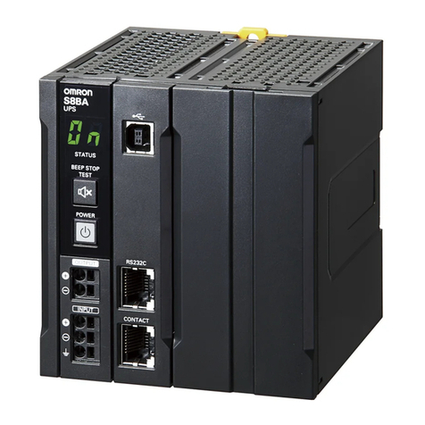
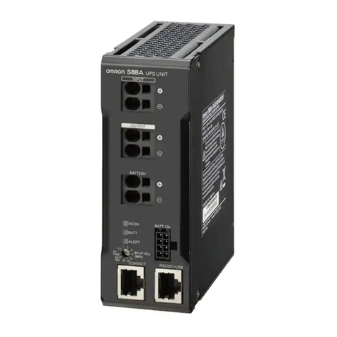
Omron S8T-DCBU-01 User manual

DC Backup Block for S8TS S8T-DCBU-01 1
DC Backup Block for S8TS
S8T-DCBU-01
DC Backup Block for S8TS
for Preventing 24 VDC Outages due to
Instantaneous Power Failures
• Supplies 24 VDC for a fixed period of time even during
AC input outages to considerably improve system reliability.
• Block Power Supply Basic Block is connected by the Bus Line
Connector.
Simple system configuration
• Alarms are notified by indication on main unit and by alarm
signal output.
Block Power Supply Basic Block
DC Backup Block
Ordering Information
■DC Backup Block (See note 1.)
Note: 1. One S8T-BUS03 Connector is included as an accessory.
2. The output current can be selected by a switch.
■Bus Line Connector
Note: One package contains 10 S8T-BUS03 Connectors.
■Battery Holder
■Basic Block
Note: Use S8T-DCBU-01 in a pair with the Block Power Supply Basic Block.
Output voltage Output current Model number
24 V 3.7 A/ 8 A (See note 2.) S8T-DCBU-01
Type Number of Connectors Model number
DC line bus 1 Connector S8T-BUS03
10 Connectors (See note.) S8T-BUS13
Model number
S82Y-TS01
Type Output voltage/Output current Model number
Screw terminal type With Bus Line Connectors 24 V/ 2.5 A S8TS-06024-E1
Without Bus Line Connectors S8TS-06024
Connector terminal type With Bus Line Connectors S8TS-06024F-E1
Without Bus Line Connectors S8TS-06024F

2DC Backup Block for S8TS S8T-DCBU-01
Basic Configuration
■Number of Multi-Connected S8TS-06024@and Designated Battery
Note: 1. The designated battery is made by Matsushita (Panasonic).
2. The designated battery is rated at 12 V. Use two batteries in series.
3. S8T-DCBU-01 shall be connected with S8TS-06024@when in use.
4. Consult Panasonic representative when purchasing batteries.
Area where battery is sold Japan Europe Areas other than Japan
and Europe
Overcurrent
protection
operating
point selector
Max. No. of
connected
S8TS-06024@
units
LC-
P122R2J LC-
P123R4J LC-
R122R2PG LC-
R123R4PG LC-
R122R2P LC-
R123R4P
5.7 A (typ.) 2 (3 in the case of N+1
redundant operation) Yes Yes Yes Yes Yes Yes
11.7 A (typ.) 4 (5 in the case of N+1
redundant operation) —— Yes —— Yes —— Yes
S8T-BUS01
Bus Line Connector
(Order separately)
Connect to
Loads
Connect to
Batteries
Connect to
AC Lines
S8TS-06024@
Block Power Supply Basic Block
(Order separately) S8T-BUS03 Bus Line Connector
S8T-DCBU-01 DC Backup Block
S82Y-TS01 Battery Holder
(
Order se
p
aratel
y)
Note: One S8T-BUS03 Connector is included with the
S8T-DCBU-01 DC Backup Block.
Note: S8T-BUS01 Connector is used
for connecting to the
S8TS-06024@Basic Block.

DC Backup Block for S8TS S8T-DCBU-01 3
Specifications
■Ratings/ Characteristics
Note: 1. Refer to Backup Time (Reference Value) on page 10 for details.
2. Refer to Functions on page 7 for details.
3. The output is specified at power output terminals.
4. Specified by performance of S8TS-06024@Basic Block.
5. Specified by S8TS-06024@connection.
6. Specified by battery performance.
7. Set the detection current to 20 mA ×N when S8TS-06024@Basic Block N Blocks are connected.
8. Be sure to mount End Plates (PFP-M) on both ends of the Power Supply.
9. To be compliant with UL508 (Class2: per UL1310), take one of following each measure. Note that the number of
S8TS-06024@to be connected to the S8T-DCBU-01 shall be one.
•Connect S8T-DCBU-01 to S82Y-TS01 having its fuse replaced with an UL-Listed and DC rated 32 VDC min./
3 A max. one.
•Connect an UL-Listed and DC rated 32 VDC min./ 2.5 A max. fuse at the location shown in Fig.1.
Item Model S8T-DCBU-01
Input Voltage 24 to 28 VDC
Output
(See note
3.)
Normal
operation Voltage 24 VDC (See note 4.)
Load variation influence
(See note 5.) 6% max.
Backup
operation Voltage 21.0 to 27.4 VDC (See note 6.)
Min. output
current
LC-
@
122R2
@@ 0.11 A
LC-
@
123R4
@@ 0.17 A
Backup time
(reference value)
(See note 1.)
LC-
@
122R2
@@ 8 min/ 3.7 A (at 25°C, battery fully charged, start of battery service life)
LC-
@
123R4
@@ 4 min/ 8.0 A (at 25°C, battery fully charged, start of battery service life)
Charging Method Stable voltage/current charging method
Charge voltage (See note 2.) 27.4 V/ 26.2 V (typical)
Max. charge current 0.35 A (typical)
Overvoltage protection (See note 2.) Yes (30 V typical)
Additional
functions Protection
functions Overdischarge protection
(See note 2.) Yes (18.5 V typical)
Overcurrent protection
(See note 2.) Yes (5.7 A/ 11.7 A typical)
Battery misconnection
protection (See note 2.) Yes
Input
function Backup ON/OFF input
(See note 2.) Yes
Output
functions Output indicator Yes (color: green)
Battery status indicator
(See note 2.) Yes (color: red)
Battery status output
(See note 2.) Yes (relay: 24 VDC, 0.1 A)
Backup status indicator Yes (color: red)
Operation mode output Yes (relay: 24 VDC, 0.1 A)
Other Ambient operating temperature
(See note 5.)
Operating: Refer to the derating curve in
Engineering Data
. (with no condensation or icing)
Storage: −25 to 65°C
Ambient humidity Operating: 25% to 85%; Storage: 25% to 90%
Dielectric strength
(See note 5. and 7.) 3.0 kVAC for 1 minute (between all S8TS-06024@AC input terminals, and all S8T-
DCBU-01 terminals/ all S8TS-06024@output terminals; detection current: 20 mA)
2.0 kVAC for 1 minute (between all S8TS-06024@AC input terminals and GR termi-
nals; detection current: 20 mA)
1.0 kVAC for 1 minute (between all S8T-DCBU-01 terminals/ all S8TS-06024@output
terminals, and between GR terminals; detection current: 20 mA)
Insulation resistance (See note 5.) 100 MΩmin. (between all S8T-DCBU-01 terminals and all S8TS-06024@outputs, and
between all S8TS-06024@AC inputs and GR terminals) at 500 VDC
Vibration resistance (See note 5. and 8.)
10 to 55 Hz, 0.375-mm single amplitude for 2 h each in X, Y, and Z directions
Shock resistance (See note 5. and 8.) 150 m/s2, 3 times each in ±X, ±Y, and ±Z directions
Electromagnetic interference (See note 5.)
Conforms to FCC Class A, EN50081-2/1993
EMS (See note 5.) Conforms to EN61000-6-2/1999
Approved standards
UL: UL508 (Listing, Class 2: Per UL1310) (See note 9.), UL60950, UL1604 (Class I /Division 2)
cUL: CSA C22.2 No.14, No.60950, No.213 (Class I /Division 2)
EN/VDE: EN50178 (=VDE0160), EN60950 (=VDE0806)
Size 120 ×120 ×43 mm
Weight 350 g
S8T-
DCBU-
01
S8TS-
06024
LN
+V
-V +V
-V
(Fig. 1)

4DC Backup Block for S8TS S8T-DCBU-01
Connections
■Block Diagram
■Installation
DC Backup Block
+
−
DC (+)
DC (−)
+V
−V
X
X
Charging
circuit
Input
voltage
detection
Detection resistorDischarge circuit
Battery misconnection
protection circuit
Bypass D
Fuse
2.0 A
Charging
control
circuit
Battery
Backup
ON/OFF
input
Connected
to Bus Line
Connector
Connected
to Bus Line
Connector
Overcurrent
detection
DC OUTPUT
Operation
mode
output
Battery
status
output
Overdis-
charge
detection
Battery
voltage
detection
S8T-DCBU-01
2
1
3
4
5
6
7
8
9
10
11
15 21
23
24
2526
22
14
1917
18 20
1312
16
1
2
3
4
5
6
Operation mode output
(OPN MODE)
Battery status output
(BAT LOW)
Backup ON/OFF input
(ON/OFF)
COM
Normal
Backup
COM
OK
LOW
S8T-DCBU-01
(1) Backup: Operation Mode Output Relay
(2) COM: Operation Mode Output Relay
(3) Normal: Operation Mode Output Relay
(4) LOW: Battery Status Output Relay
(5) COM: Battery Status Output Relay
(6) OK: Battery Status Output Relay
(7) ON/OFF: Backup ON/OFF Input
(8) GND: Backup ON/OFF Input
(9) Output Indicator (DC ON: Green)
(10) Backup Status Indicator (BUCKUP: Red)
(11) Battery Status Indicator (BAT LOW: Red)
(12) Battery Connector Terminal (−)
(13) NC
(14) Battery Connector Terminal (+)
(15) Slider
(16) Short Bar
(17) DC Output Terminal (−V)
(18) NC
(19) DC Output Terminal (+V)
(20) Track Stopper
(21) Battery Connector Terminal Block
(22) Connected to Bus Line Connector
(23) DC Output Terminal Block
(24) Terminal Block Cover
(25) Charge Voltage Selector Switch
(26)
Overcurrent Protection Function Selector Switch

DC Backup Block for S8TS S8T-DCBU-01 5
Bus Line Connector
S8T-BUS03
(1) Selector
(2) Ground Terminal
(3) Parallel Operation Signal Terminal
(4) DC Output Terminal (+)
(5) DC Output Terminal (−)
Battery Holder
S82Y-TS01
(1) Battery Tray
(2) Fuse
(3) Terminal Block
(4) Switch
(5) Battery A (Order separately)
(6) Battery B (Order separately)
(7) Protection Cover
Operation
Backup Function
(Backup status indication, Operation mode output)
S8T-DCBU-01 detects output voltage drop of S8TS-06024@to
switch to backup operation.
Backup operation continues for about 7 seconds even after the out-
put voltage of S8TS-06024@is restored.
Note: 1. If this state occurs, a probable cause is an S8TS-06024@
overload or it is out of order. Immediately eliminate the
cause of the trouble.
2. If switching between backup operation and Normal opera-
tion is repeated, the output voltage changes accordingly.
3. The contact capacity of the relay is 24 VDC 0.1A.
4. Upon a steep load fluctuation, the output voltage of S8TS-
06024@drops to switch to backup operation.
5. The maximum inrush current specified below (on assump-
tion with a 56000µF capacitive load) flows when backup op-
eration starts.
Charging Circuit
Charging Time (Reference Values)
Note: The battery takes the time specified above to be charged.
If power failure occurs at time shorter than the necessary
charging time, backup operation may not continue for the nec-
essary time.
Output Voltage Adjustment for
S8TS-06024@
The DC backup block detects output voltage drop of connected
S8TS-06024@to switch to backup operation.
Do not set the output voltage of S8TS-06024@to lower than the fac-
tory shipment setting because, even though the output voltage of
S8TS-06024@is adjustable with Output voltage adjustor. Otherwise,
it may operate in the backup operation mode.
1
2
3
4
542
15
6
3
7
Backup
status LED
(BACKUP: Red)
Relay
(OPNMODE
)
Power failure Continuous
backup
operation
Lit Backup
(1)-(2): ON
Failure
of one
unit of
S8TS-
06024@
During
operation of
one unit of
S8TS-06024
@
During
operation of
multipleunits
of S8TS-
06024
@
Repetition of
switching
between
Normal
operation and
Backup
operation at
an interval of
about 7
seconds
Blink at an
interval of
about 7
seconds
Repetition of
switching
between
Normal
((3)-(2): ON)
and BACK
UP
((1)-(2): ON)
Upon activation of
overcurrentprotection
function of S8TS-
06024
@
1
2
3
COM
Normal
Backup
LED lit
(BACKUP: Red) Relay (OPN MODE)
(1)-(2): ON
Operation mode
output relay
Indicator
Battery used 100% charged 80% charged
LC-@122R2@@ 24 to 48 hours 5 hours
LC-@123R4@@ 8 hours
45
025 ms Time
Battery charge status: Fully charged
Ambient temperature: 40˚C
Input capacitor of connected equipment: 56,000 µ
F
Load power: 192 W
Inrush current (A)

6DC Backup Block for S8TS S8T-DCBU-01
Wiring Length Between S8T-DCBU-01
and Battery
Connect S8T-DCBU-01 and the battery using a cable having a wire
diameter specified in Recommended Wire Diameter (page 14)”
within a wiring length of 1.5 m.
Because the battery voltage is monitored at the battery connecting
terminal, a large wiring impedance increases the voltage drop from
wiring, reducing the backup time.
Battery Holder S82Y-TS01
We recommend using the S82Y-TS01 Battery Holder for connecting
and installing the battery. Take the following points into consideration
when using the S82Y-TS01:
(1) Contact between leaking battery fluid and metal parts having an
electric potential may cause smoke or fire. To prevent this, the
Battery Holder uses a resin battery tray.
(2) The inrush current shown below flows when backup operation is
switched to. The peak value and time of this inrush current vary
according to the capacity of the input capacitor of the connected
equipment, battery charge status, battery wiring length, and
ambient temperature. The switch and fuse of the S82Y-TS01
are
selected taking this inrush current into consideration. When
replacing the fuse, use only the specified fuse. (Littelfuse,
257015 (15 A))
(3) In the event that the battery generates inflammable gases, place
the switch and fuse away from the convection path of the inflam-
mable gas to prevent the switch or fuse from causing ignition and
explosion.
(4) Storing the S8T-DCBU-01 still connected to the battery may
cause the battery to discharge and considerably reduce the ser-
vice life of the battery. To prevent this, turn the switch OFF.
Mounting and Removing the Bus Line
Connector
Pay attention to the following points to maintain electrical character-
istics.
•Do not insert/remove the Connectors more than 20 times.
•Do not touch the Connector terminals.
•To remove the Connectors, insert a flat-bladed screwdriver alter-
nately at both ends.
S8T-BUS03
Use S8T-BUS03, which only DC lines are connected with. (AC line
not connected).
S8T-BUS03 is equipped with a selector for the prevention of errone-
ous connection of a different output voltage specification of the
power supply unit. Slide the selector in the 24 V position.
Mounting
Mounting Direction
Use standard mounting only. Using any other mounting method will
prevent proper heat dissipation and may result in deterioration or
damage of internal elements.
Stopping the Equipment
To stop the connected equipment for maintenance, it is recom-
mended to eliminate the needs for backup action. Then turn off the
battery holder and turn OFF the AC power.
45
025 ms Time
Battery charge status: Fully charged
Ambient temperature: 40˚C
Input capacitor of connected equipment: 56,000 µ
F
Load power: 192 W
Inrush current (A)
Standard mounting Yes
Back down mounting No
Other mounting No
−V+V −V+V
−LNGR
S8T-BUS03S8TS-06024@
S8T-DCBU-01
+
Selector
Standard mounting Back down mounting

DC Backup Block for S8TS S8T-DCBU-01 7
Operation Check
After connecting S8TS-06024@and S8T-DCBU-01, it is recom-
mended to check the DC Backup Block if it is correctly operating in
the following procedure.
1. Turn ON the Battery Holder.
2. Turn ON the AC power to the S8TS-06024@.
3. Wait for 10 sec. or more then check if the DC Backup block is in
Status 1.
4. Turn OFF the AC power of the S8TS-06024@.
5. Confirm that Backup operation is correctly performed in Status 2.
6. Turn ON the AC power of the S8TS-06024@.
Note: 1. Perform operation checks after arranging a state where no
fault occurs even if the connected devices are turned OFF
in the midway.
2. The operation mode may not changed to Backup, if AC
power is turned OFF within 10 sec. at Step 3.
■Functions
Charging Voltage Selector
Select either 27.4 V or 26.2 V at the charging
voltage selector to select the charging volt-
age.
Because the battery manufacturer recom-
mends 27.4 V as charging voltage, it is rec-
ommended to charge at 27.4 V.
In this case, 27.4 VDC, which is the charging
voltage of the batteries, may output depend-
ing on the state of connected load when the
operation changes to Backup.
Note: If the battery is charged at 26.2 V, the battery capacity decreas-
es each time the battery is charged, and the backup time grad-
ually decreases. (Reference value)
Overvoltage Protection Circuit
If the charge voltage is about 30 V or above, the charge voltage is
cut off to prevent the battery from being overcharged.
How to Reset Overvoltage Protection
Reset Overvoltage protection with following steps after arranging a
state where no fault occurs even if the connected devices are turned
off in the midway.
1. Turn OFF the Battery Holder switch.
2. Turn OFF the AC power of the S8TS-06024@.
3. Leave the power supply OFF for 1 minute or more.
4. Turn ON the Battery Holder switch.
5. Turn ON the AC power of the S8TS-06024@again.
Note: 1. Remove the cause before turning on the AC power again.
2. As an AC input OFF status is the same as a power failure,
the S8T-DCBU-01 will perform backup operation. Some-
times charging cannot be performed for therequired backup
time as the battery is not sufficiently charged. For this rea-
son, first make sure that backup operation is not needed be-
fore turning the battery holder switch and then the AC input
OFF.
3. The off time necessary for restoration assumes connection
of five units of S8TS-06024@, without a load, and fully
charged batteries.
Overcurrent Protection Operating Point
Selector
5.7 A (typ.) or 11.7 A (typ.) can be selected
with the selector as an overcurrent protection
operating point during backup operation.
Select 5.7 A (typ.) for one or two units of
S8TS-06024@(or three units during N+1
redundancy operation), or select 11.7 A (typ.)
for three or four units (or five units during N+1
redundancy operation). The shipment set-
ting is 5.7 A (typ.).
4
5
6
1
2
3
COM
OK
LOW
Relay (BAT LOW)
(6)-(5): ON
Battery status
output relay
LED lit
(DC ON: Green) Relay (OPN MODE)
(3)-(2): ON
Operation mode
output relay
Indicator
COM
Normal
Backup
4
5
6
1
2
3
COM
LOW
Relay (BAT LOW)
(6)-(5): ON
Battery status
output relay
LED lit
(DC ON: Green)
LED lit
(BACKUP: Red)
Relay (OPN MODE)
(1)-(2): ON
Operation mode
output relay
Indicator
COM
Normal
Backup
OK
Capacity reduction in each charge-and-discharge cycle
At 25°C Reduction by 10%
At 0°C Reduction by 20%
Terminal
block cover
Overcurrent protection
function selector
Section A
Charge voltage selector
Enlarged View of
Section A
Overcurrent protection
function selector
Enlarged View of
Section A

8DC Backup Block for S8TS S8T-DCBU-01
Overcurrent Protection Function
During Normal Operation
An overcurrent is notified in the following way.
•LED (BAT LOW: Red) lights up.
•Relay (BAT LOW) is in the LOW mode ((4)-(5): ON).
If power failure occurs in this state, an overcurrent protection function
is activated to fail to backup.
During Backup Operation
The overcurrent protection operating point can be selected from
either 5.7 A (typ.) or 11.7 A (typ.) using the selector. The output is cut
off when overcurrent protection is activated.
Note: Continuation of operation in the overcurrent status may cause
deterioration or breakage of internal elements.
Overdischarge Protection Function
When the battery connecting terminal voltage drops down to about
18.5 V, backup operation is stopped to protect the battery against
overdischarge.
Backup ON/OFF Input Function
If the backup ON/OFF input terminals are short-circuited, backup is
enabled, while if the terminals are open, backup is disabled. The ter-
minal is non-voltage input type and the short and open circuits are
specified below.
With the shipment setting, a short bar is installed to short-circuit
across the backup ON/OFF input terminals.
When the backup ON/OFF input terminals are open, the following
signs inform that backup is disabled.
•LED (BAT LOT: Red) is lit.
•Relay (BAT LOW) is in the LOW mode ((4)-(5): ON).
Protection Against Erroneous Battery
Connection
When the DC backup block is turned on, the charging circuit is sepa-
rated if battery connection terminal voltage become below about
15.5 V. This function protects the battery and the main body upon
erroneous connection of the batteries (with reverse polarity or with
only one 12 V battery).
Activation of the erroneous battery connection function is notified in
the following way.
•LED (BAT LOW: Red) lights up.
•Relay (BAT LOW) is in the LOW mode ((4)-(5): ON).
Battery Status Indication and Battery
Status Output
A battery charging/discharging fault (1. through 4. described below)
is notified in the following way.
If power failure occurs in this state, backup operation does not start
or the backup time becomes shorter. Remove the cause of the fault
immediately.
1. About 22.5 V or lower battery connecting terminal voltage.
2. Activation of erroneous battery connection protection function.
3. Open battery ON/OFF input terminals.
4. Overcurrent status during Normal operation.
Note: The contact capacity of the relay is 24 VDC 0.1 A.
Short Impedance with 1 kΩ
Flowing current at 0 Ω: About 2 mA
Residual voltage: 1 V or below
Open Impedance: 400 kΩor more
4
5
6
COM
OK
LOW
LED lit
(
BAT LOW: Red
)
Relay (BAT LOW)
(
4
)
-
(
5
)
: ON
Battery status
output relay
Indicator

DC Backup Block for S8TS S8T-DCBU-01 9
Engineering Data
■Derating Curve
Note: 1. Add one more S8TS-06024@Basic Block if a redundant system is used.
2. If natural air circulation is limited, use the forced air cooling to prevent overheating.
3. The peripheral temperature is specified at the place 50 mm downward from the main body of the DC Backup Block.
4. The operating temperature range of the battery is 0 to 40°C; it is different from that of S8T-DCBU-01.
And the ambient temperature of battery is specified with the temperature at the battery surface.
5. The amount of output wattage at multi-connected S8TS-06024@become smaller than the simple sum of each wattage, since S8T-DCBU-
01 consumes energy from S8TS-06024@.
Number of S8TS-06024@units S8TS-06024@rated input Derating curve Rated output power
1 200 to 240 VAC *1 36 W
100 to 120 VAC *2
1 (+1) 100 to 120 VAC/200 to 240 VAC *3 30 W
2 *4 88.8 W
2 (+1) *5 76.8 W
3 *6 146.4 W
3 (+1) *7 128.4 W
4 *8 192 W
4 (+1) *9 168 W
40
35
30
25
20
15
10
5
0
−20 −100 102030405060
*2
*3
*1
36
S8T-DCBU-01
100
80
60
40
20
0
−20 −100 102030405060
*4
*5
88.8
76.8
160
140
120
100
80
60
40
20
0
−20 −100 102030405060
*6
*7
146.4
128.4
S8T-DCBU-01 S8T-DCBU-01
200
150
100
50
0
−20 −100 102030405060
*8
*9
192
168
S8T-DCBU-01
Output power (W)
Ambient temperature (˚C)
Output power (W)
Ambient temperature (˚C)
Output power (W)
Ambient temperature (˚C)
Output power (W)
Ambient temperature (˚C)

10 DC Backup Block for S8TS S8T-DCBU-01
■Time Charts
Startup
Note: Backup operation is not possible during the period (7 seconds (typical)) that the bat-
tery status output relay is LOW after the S8T-DCBU-01 is started up.
Power Failure (When the Battery
Voltage does not Reach the BAT LOW
Voltage)
Note: Backup operation is continued for seven seconds after the power is restored from a
power failure.
Power Failure (When the Battery
Voltage Reaches the BAT LOW Voltage)
Note: When the battery voltage falls below 22.5 V (typical), the status of the battery status
output relay changes to LOW.
Power Failure (When the Battery
Voltage Reaches the Overdischarge
Protection Voltage)
Note: When the battery voltage falls below 22.5 V (typical), the status of the battery status
output relay changes to LOW, when the battery voltage falls below 18.5 V (typical),
backup operation is stopped.
■Backup Time (Reference Value)
AC input
Output voltage of the
S8TS-06024@
Output voltage of the
S8T-DCBU-01
Battery voltage
Backup
((1)-(2))
Operation
mode output Normal
((3)-(2))
LOW
((4)-(5))
Battery
status output 7 seconds (typical) (See note.
)
OK
((6)-(5))
Power failure time
7 seconds (typical)
(See note.)
AC input
Output voltage of the
S8TS-06024@
Output voltage of the
S8T-DCBU-01
Battery voltage
Backup
((1)-(2))
Operation
mode output Normal
((3)-(2))
LOW
((4)-(5))
Battery
status output OK
((6)-(5))
Power failure time
7 seconds (typical) (See note.)
22.5 V (typical) (See note.)
AC input
Output voltage of the
S8TS-06024@
Output voltage of the
S8T-DCBU-01
Battery voltage
Backup
((1)-(2))
Operation
mode output Normal
((3)-(2))
LOW
((4)-(5))
Battery
status output OK
((6)-(5))
22.5 V (typical) (See note.)
18.5 V (typical) (See note.)
AC input
Output voltage of the
S8TS-06024@
Output voltage of the
S8T-DCBU-01
Battery voltage
Backup
((1)-(2))
Operation
mode output Normal
((3)-(2))
LOW
((4)-(5))
Battery
status output OK
((6)-(5))
80
70
60
50
40
30
20
10
00255075100
80
70
60
50
40
30
20
10
00 50 100 150 200
Backup time (Minute)
Output capacity (W)
Backup Time when
LC-@122R2@@ is Used Backup Time when
LC-@123R4@@ is Used
Backup time (Minute)
Output capacity (W)
Note: 1. Backup time conditions
•Ambient temperature: 25˚C
•Battery: New product fully
charged to 27.4 V
•Length of wire between
S8T-DCBU-01 and battery: 1.5 m
2. The backup time changes depend-
ing on the capacity of connected
equipment, ambient temperature,
and battery service life.

DC Backup Block for S8TS S8T-DCBU-01 11
■Battery Replacement
The lead battery deteriorates.
Replace the battery while referring to the following replacement
period as a reference.
Note: 1. Battery deterioration accelerates when its service life limit
draws near.
2. The battery replacement timing assumes the battery has
reached half its original capacity.
3. The life varies according to the storage and operating envi-
ronment, output wattage, and the frequency of backup op-
eration.
4. Fire may be caused in worst case, if batteries are continu-
ously used beyond its replace timing. Replace batteries pe-
riodically to avoid the worst case.
1. Replacement Guideline
Replace the battery using the following table as a guideline:
Note: The conditions in the table above is estimated as: charged at
27.4 V, discharged with 8 A (for LC-@123R4@@), 3.7 A (LC-@
122R2@@), backup operation once a month bases.
2. Measuring Backup Time
The backup time can be measured by the procedure below. When
the battery is new, first measure the initial backup time value.
Replace the battery if backup operation is not performed for the
required backup time during periodic maintenance or the backup
time has fallen below the half or less of initial value.
Note: 1. Make sure that at least 48 hours have elapsed since the
previous backup operation, and that the battery is correctly
connected, and then measure the backup time.
2. Measure the backup time after making sure that no prob-
lems will occur as a result of stopping power supply.
(1) Turn the AC power line OFF, and back up the S8T-DCBU-01.
(2) Measure the time that the battery status output relay turns to
LOW ((4)-(5): ON) after the operation mode output relay is
backed up ((1)-(2): ON). (This is the backup time.)
(3) When the battery status output relay turns LOW ((4)-(5): ON),
turn the AC power line ON.
Periodic Inspection of the Battery
We recommend periodically inspecting the battery as follows:
•Check the battery voltage. (In a 27.4 V series connection, make
sure that each battery is charged to 13.7 V.)
•Check battery wiring and connections. (Check the batteries and
S8T-DCBU-01 connections for loose screws.)
•Make sure that backup operation is performed normally in a simu-
lated power failure state.
Note: Check the backup operation after making sure that no prob-
lems will occur as a result of stopping power supply.
Dimensions
Note: All units are in millimeters unless otherwise indicated.
Battery Ambient
temperature Life of battery Approximate
replacement
interval
LC-R122R2@@
LC-R123R4@@ 20 °C 2 to 3 years 2 years
30 °C 1 to 1.5 years 1 year
40 °C 0.5 to 0.75 years 0.5 years
LC-P122R2@@
LC-P123R4@@ 20 °C 4 to 6 years 4 years
30 °C 2 to 3 years 2 years
40 °C 1 to 2 years 1 year
Backup time
22.5 V (typical)
AC input
Output voltage of the
S8TS-06024@
Output voltage of the
S8T-DCBU-01
Battery voltage
Backup
((1)-(2))
Operation
mode output Normal
((3)-(2))
LOW
((4)-(5))
Battery
status output OK
((6)-(5))
S8T-DCBU-01
26.2V-27.4V CHARGE V
9.5A-4.4A OCP
120
543
2.5
10
80.7 35
120
10
4
DC Backup Block
5.6
(Sliding: 15 max.)
Six, M4
with square washer
130 max.

12 DC Backup Block for S8TS S8T-DCBU-01
■DIN Track
Note: All units are in millimeters unless otherwise indicated.
S8T-BUS03 28.6
24 7.6
18 42.5
13
5
2
35
70
10
Bus Line Connector
5.5
Sliding
5.5
Sliding
52.75
212
222.25
114
8
185.7
82
S82Y-TS01
Battery Holder
8 dia.
PFP-100N
PFP-50N 4.5
15 25 25
10 10
1,000 (500) * 25 25 15(5) *
35±0.3
7.3±0.15
27±0.15
1
Mounting Track (Material: Aluminum)
* Values in parentheses
are for the PFP-50N.
PFP-100N2 4.5
15 25 25
10 10
1,000 25 25 15 11.5
29.2242735±0.3
16
Mounting Track (Material: Aluminum)
PFP-M
50
11.5
10 4.8
1.3
1.8
1
10 6.2 1.8
35.5 35.3
End Plate
M4 spring
washer
M4 × 8
pan-head screw

DC Backup Block for S8TS S8T-DCBU-01 13
Precautions
!WARNING
[Installation and Environment]
Do not use the battery in a tight area or near an object that gener-
ates sparks, such as contactors, relays, or static charge. The bat-
tery may generate flammable gases when it is charged, so that
fire or explosion may be caused.
Tighten the terminal screws with torque 1.08 N·m and tighten the
connector screw and threaded flange with torque 0.20 N·m.
Loose screws may cause fire.
The tightening torque for terminal screws on the Battery Holders
is 0.74 N·m. Loose screws may result in fire.
Do not remove any connector cover unless using Bus line con-
nectors. Electric shock may be caused.
When connecting the Basic Block and DC Backup Block, lock the
slider and rail stopper. If they are locked insufficiently, linkage
may be disconnected due to vibration, causing electric shock.
Do not use batteries other than the designated ones. If a battery
other than the designated ones is used, smoke and fire may be
caused.
Do not apply resin including a migrational plasticizer on the bat-
tery. Cracks will generate in the battery to cause leakage of elec-
trolyte.
When using metallic tools to install the battery to the Battery Hold-
er, use one insulated with vinyl tape or the like. A short circuit may
cause heat or spark, possibly causing a broken battery, fire or ex-
plosion.
Connect the battery correctly. Wrong connection may cause
smoke or fire.
Do not operate the battery in an area exceeding 40°C. The bat-
tery may deteriorate quickly and cause fire.
(Operating temperature range of a battery: 0 to 40°C)
Do not use the battery in an area including corrosive gases. Fire
may be caused in the worst case.
Do not use new and old, different types, and different residual ca-
pacities of batteries mixed. Smoke and fire may be caused.
Do not use the DC Backup Block for the applications in which
connected load causes frequent inrush current.
See “Additional Precautions According to UL1604” for UL1604
conformance.
[Operation]
Follow the precautions of a battery when using. A battery could
be dangerous if it is used incorrectly.
Do not touch the product during power-on, and immediately after
power-off. Hot surfaces may cause heat injury.
Do not add or separate the DC Backup Block during power-on.
Electric shock may be caused.
Replace the battery immediately if it is fully drained. If the fully
drained battery is kept in use, fire may be caused.
If malodor, abnormal noise, smoke or liquid is issued from the
battery, turn off the switch of the Battery Holder. Continuation of
operation in this state may cause fire.
Keep away from electrolyte leaking from the battery. Lost sight or
burns may be caused. Flush electrolyte entering eyes or contact-
ing the skin with a large volume of clean water and get medical at-
tention.
Do not use the Battery Holder in locations subject to shocks or vi-
brations. Shocks or vibrations may cause battery performance to
deteriorate.
[Maintenance]
Do not disassemble the product or touch internal parts during
power-on. Electric shock may be caused.
When performing maintenance, turn OFF the AC power and Bat-
tery Holder switch. If only the AC power is turned off, the batteries
supply power and connected devices do not stop.
Be careful during installation of the battery or Battery Holder or re-
placement of the battery to avoid dropping the battery. A dropping
battery may cause injuries and burns caused by leaking electro-
lyte.
Do not install or replace the battery in the presence of flammable
gases. Sparks generated when the battery is connected may
cause explosion or fire.
Do not disassemble or remodel the battery. Diluted sulfuric acid
may leak, possibly causing loss of sight or burns.
Do not short-circuit the battery using a metallic matter. Electric
shock, fire or burns may be caused.
Observe a self-imposed control, lows and regulations for disposal
or collection (recycle) of a battery. Explosion may be caused if a
battery is thrown in fire.

14 DC Backup Block for S8TS S8T-DCBU-01
Mounting
To improve the long-term reliability of devices, give due consideration
to heat dissipation when mounting. With the S8T-DCBU-01, heat is
dissipated by natural convection. Mount Blocks in a way that allows
convection in the atmosphere around them.
When cutting out holes for mounting, make sure that cuttings do not
enter the interior of the products.
Before turning the Power Supply ON, be sure to remove sheets that
were used as covers during mounting, and make sure that heat
release is not obstructed.
Connect the S8T-DCBU-01 to the right or left end of S8TS-06024@
Basic Blocks.
Installation/ Wiring
Ensure that input and output terminals are wired correctly.
Close the terminal cover to avoid short circuit of terminals with a for-
eign object.
Use the following material to wire to load and to the batteries for pre-
venting wiring material from smoke or fire caused by the abnormal
load.
Do not press down the terminal block or connector terminal at more
than 100 N force when tightening the terminal screws.
Be sure to remove the sheets covering the product for machining
before power-on.
Recommended Wire Diameter
Installation Environment
Do not use the Power Supply in locations subject to shocks or vibra-
tions. In particular, install the Power Supply as far away as possible
from contactors or other devices that are a vibration source. Be sure
to mount End Plates (PFP-M) on both ends of the Power Supply.
Install the Power Supply well away from any sources of strong, high-
frequency noise.
Installing/ Storage Environment
•Store the product with ambient temperatures −25 to +65°C, and rel-
ative humidity 25 to 90 %.
•Since the internal components could be deteriorated or broken
under the high temperature and high load (outside the derating
curve), do not use the DC Backup Block.
•Use the product with relative humidity 25 to 85 %.
•Avoid places where the product is subjected to direct sunlight.
•Avoid penetration of metal chips when processing mounting holes.
•Avoid places where the product is subjected to penetration of liquid,
foreign substance or corrosive gas.
•Avoid places subjected to shock or vibration. A device such as a
conductor may be a vibration source. Set the DC Backup Block as
far as possible from possible sources of shock or vibration. Addi-
tionally, install the end plate (PFP-M) to both ends of the power
supply.
•If the DC Backup Block is used in an area with excessive electronic
noise, be sure to separate the DC Backup Block as far as possible
from the noise sources.
When Storing the battery for an extended period of time, observe the
following two precautions. If not observed, the life of battery could be
extremely short.
•Repeat charging in the period designated by the manufacturer of
the battery. The battery self-discharges during storage to decrease
the capacity.
•Turn OFF the battery holder switch, or disconnect the batteries
from S8T-DCBU-01.
Handling of Bus Line Connector
Do not drop or give strong impact on the Bus line connector.
DIN Track Mounting
To mount the Block on a DIN track, hook portion (A) of the Block onto
the track and press the Block in direction (B).
To dismount the Block, pull down portion (C) with a flat-blade screw-
driver and pull out the Block.
Overcurrent
protection
operating point
selector
Number of
connected
S8TS-06024@
Recommendedwire
diameter
5.7 A (typ.) 1, 2 AWG 14 to 18
(cross-sectionalarea:
0.823 to 2.081 mm2)
3 AWG 14 to 16
(cross-sectionalarea:
1.309 to 2.081 mm2)
11.7 A (typ.) 3, 4, 5 AWG 14
(cross-sectionalarea:
2.081 mm2)
*1*1
*1 *1
*2
S8TS-06024@S8TS-06024@
*3
*4
S8T
-DCBU-01
*1. Convection of air *3. 75 mm min.
*2. 75 mm min. *4. 10 mm min.
S8T-DCBU-01S8T-DCBU-01S8T-DCBU-01
S8TS-
06024@S8TS-
06024@S8T-
DCBU-
01
S8T-
DCBU-
01
S8T-
DCBU-
01
LN
S8TS-
06024@
LN
S8TS-
06024@
LN
S8TS-
06024@
LN
S8TS-
06024@
LN
B
A
C30 mm min.
Track sto
pp
er

DC Backup Block for S8TS S8T-DCBU-01 15
Troubleshooting
This page lists the errors that may occur when the S8T-DCBU-01 is used, along with their probable causes and remedies.
Check the relevant item.
When Probable cause Description Remedies
Installation S8T-DCBU-01 cannot be
connected. The Bus Line Connector is provided with a
selector for preventing misconnection of 12 V
and 5 V specification S8TS units. For this
reason, connection is not successful if different
specification units are installed.
Set the selector on the Bus Line Connector
(provided) to 24 V.
Refer to S8T-BUS03 on page 6 for details.
When checking
the performances
Refer to
Operation Check
on page 7 for
details.
The S8T-DCBU-01 output
indicator does not light in
operation check procedure,
step 2.
The S8T-DCBU-01 operates by the output of
the S8TS-06024@. A probable cause is that the
Bus Line Connector is not connected as the
input voltage is connected by the Bus Line
Connector (provided).
Connect the S8T-DCBU-01 to S8TS-06024@
using the Bus Line Connector (provided).
Refer to Basic Configuration on page 2 for
details.
The connected S8TS-
06024@does not operatein
operation check procedure,
step 2.
A probable cause is that the S8T-DCBU-01 is
connected between S8TS-06024@Basic
Blocks.
The S8T-BUS03 Bus Line Connector for
connecting the S8T-DCBU-01 is not connected
to the AC power line. Connect the S8T-DCBU-
01totheleftorrightendofS8TS-06024@Basic
Blocks.
The battery status indicator
is lit even 10 seconds or
more after the power is
turned ON in operation
check procedure, step 3.
A probable cause is that the battery was
connected with the + and −polarities reversed. Connect the battery correctly.
Refer to Protection Against Erroneous Battery
Connection on page 8 for details.
Aprobablecauseisthatthe batteryvoltagefalls
below about 22.5 V. (A probable cause is
battery discharge during long-term storage.)
Charge the battery before use.
Refer to Battery Status Indication and Battery
Status Output on page 8 for details.
A probable cause is that the backup ON/OFF
input is open. Short the backup ON/OFF input. (Before
shipment, the backup ON/OFF input is
shorted.)
Refer to Backup ON/OFF Input Function on
page 8 for details.
A probable cause is that the overcurrent
protection function of the connected S8TS-
06024@is active.
As energy is consumed by S8T-DCBU-01, the
total output capacity of the number of
connectedS8TS-06024@scannotbeobtained.
Connect one more S8TS-06024@Basic Block.
Refer to the Derating Curve on page 9 for
details.
A probable cause is that the overcurrent
protection function selector switch on the S8T-
DCBU-01 is set low.
When three or more S8TS-06024@Basic
Blocks are connected, set the overcurrent
protection function selector switch to 11.7 A
(typical). (The default setting is 5.7 A (typical).)
Referto OvercurrentProtectionOperatingPoint
Selector on page 7 for details.
A probable cause is that the output voltage
adjustment trimmer of the connected S8TS-
06024@is set lower than the factory set
voltage.
The S8T-DCBU-01 detects drops in the output
voltage of the S8TS-06024@and switches over
to backup operation. Adjust the output voltage
adjustment trimmer on the S8TS-06024@so
that the output in a no-load state is 24.5 V or
more.
Refer to Output Voltage Adjustment for S8TS-
06024@on page 5 for details.
The backupoperation is not
performed in operation
check procedure, step 5.
A probable cause is that inrush current during
backup operation caused the fuse on the
battery to blow.
Select a fuse taking the inrush current when
backup operation is switched to into
consideration. The recommended S82Y-TS01
Battery Holder is selected taking this inrush
current into consideration.
Refer to Battery Holder S82Y-TS01 on page 6
for details.

Terms and Conditions of Sale
1. Offer; Acceptance. These terms and conditions (these "Terms") are deemed
part of all quotes, agreements, purchase orders, acknowledgments, price lists,
catalogs, manuals, brochures and other documents, whether electronic or in
writing, relating to the sale of products or services (collectively, the "Products")
by Omron Electronics LLC and its subsidiary companies (“Omron”). Omron
objects to any terms or conditions proposed in Buyer’s purchase order or other
documents which are inconsistent with, or in addition to, these Terms.
2. Prices; Payment Terms. All prices stated are current, subject to change with-
out notice by Omron. Omron reserves the right to increase or decrease prices
on any unshipped portions of outstanding orders. Payments for Products are
due net 30 days unless otherwise stated in the invoice.
3. Discounts. Cash discounts, if any, will apply only on the net amount of invoices
sent to Buyer after deducting transportation charges, taxes and duties, and will
be allowed only if (i) the invoice is paid according to Omron’s payment terms
and (ii) Buyer has no past due amounts.
4. Interest. Omron, at its option, may charge Buyer 1-1/2% interest per month or
the maximum legal rate, whichever is less, on any balance not paid within the
stated terms.
5. Orders. Omron will accept no order less than $200 net billing.
6. Governmental Approvals. Buyer shall be responsible for, and shall bear all
costs involved in, obtaining any government approvals required for the impor-
tation or sale of the Products.
7. Taxes. All taxes, duties and other governmental charges (other than general
real property and income taxes), including any interest or penalties thereon,
imposed directly or indirectly on Omron or required to be collected directly or
indirectly by Omron for the manufacture, production, sale, delivery, importa-
tion, consumption or use of the Products sold hereunder (including customs
duties and sales, excise, use, turnover and license taxes) shall be charged to
and remitted by Buyer to Omron.
8. Financial. If the financial position of Buyer at any time becomes unsatisfactory
to Omron, Omron reserves the right to stop shipments or require satisfactory
security or payment in advance. If Buyer fails to make payment or otherwise
comply with these Terms or any related agreement, Omron may (without liabil-
ity and in addition to other remedies) cancel any unshipped portion of Prod-
ucts sold hereunder and stop any Products in transit until Buyer pays all
amounts, including amounts payable hereunder, whether or not then due,
which are owing to it by Buyer. Buyer shall in any event remain liable for all
unpaid accounts.
9. Cancellation; Etc. Orders are not subject to rescheduling or cancellation
unless Buyer indemnifies Omron against all related costs or expenses.
10. Force Majeure. Omron shall not be liable for any delay or failure in delivery
resulting from causes beyond its control, including earthquakes, fires, floods,
strikes or other labor disputes, shortage of labor or materials, accidents to
machinery, acts of sabotage, riots, delay in or lack of transportation or the
requirements of any government authority.
11. Shipping; Delivery. Unless otherwise expressly agreed in writing by Omron:
a. Shipments shall be by a carrier selected by Omron; Omron will not drop ship
except in “break down” situations.
b. Such carrier shall act as the agent of Buyer and delivery to such carrier shall
constitute delivery to Buyer;
c. All sales and shipments of Products shall be FOB shipping point (unless oth-
erwise stated in writing by Omron), at which point title and risk of loss shall
pass from Omron to Buyer; provided that Omron shall retain a security inter-
est in the Products until the full purchase price is paid;
d. Delivery and shipping dates are estimates only; and
e. Omron will package Products as it deems proper for protection against nor-
mal handling and extra charges apply to special conditions.
12. Claims. Any claim by Buyer against Omron for shortage or damage to the
Products occurring before delivery to the carrier must be presented in writing
to Omron within 30 days of receipt of shipment and include the original trans-
portation bill signed by the carrier noting that the carrier received the Products
from Omron in the condition claimed.
13. Warranties. (a) Exclusive Warranty. Omron’s exclusive warranty is that the
Products will be free from defects in materials and workmanship for a period of
twelve months from the date of sale by Omron (or such other period expressed
in writing by Omron). Omron disclaims all other warranties, express or implied.
(b) Limitations. OMRON MAKES NO WARRANTY OR REPRESENTATION,
EXPRESS OR IMPLIED, ABOUT NON-INFRINGEMENT, MERCHANTABIL-
ITY OR FITNESS FOR A PARTICULAR PURPOSE OF THE PRODUCTS.
BUYER ACKNOWLEDGES THAT IT ALONE HAS DETERMINED THAT THE
PRODUCTS WILL SUITABLY MEET THE REQUIREMENTS OF THEIR
INTENDED USE. Omron further disclaims all warranties and responsibility of
any type for claims or expenses based on infringement by the Products or oth-
erwise of any intellectual property right. (c) Buyer Remedy. Omron’s sole obli-
gation hereunder shall be, at Omron’s election, to (i) replace (in the form
originally shipped with Buyer responsible for labor charges for removal or
replacement thereof) the non-complying Product, (ii) repair the non-complying
Product, or (iii) repay or credit Buyer an amount equal to the purchase price of
the non-complying Product; provided that in no event shall Omron be responsi-
ble for warranty, repair, indemnity or any other claims or expenses regarding
the Products unless Omron’s analysis confirms that the Products were prop-
erly handled, stored, installed and maintained and not subject to contamina-
tion, abuse, misuse or inappropriate modification. Return of any Products by
Buyer must be approved in writing by Omron before shipment. Omron Compa-
nies shall not be liable for the suitability or unsuitability or the results from the
use of Products in combination with any electrical or electronic components,
circuits, system assemblies or any other materials or substances or environ-
ments. Any advice, recommendations or information given orally or in writing,
are not to be construed as an amendment or addition to the above warranty.
See http://oeweb.omron.com or contact your Omron representative for pub-
lished information.
14. Limitation on Liability; Etc. OMRON COMPANIES SHALL NOT BE LIABLE
FOR SPECIAL, INDIRECT, INCIDENTAL, OR CONSEQUENTIAL DAMAGES,
LOSS OF PROFITS OR PRODUCTION OR COMMERCIAL LOSS IN ANY
WAY CONNECTED WITH THE PRODUCTS, WHETHER SUCH CLAIM IS
BASED IN CONTRACT, WARRANTY, NEGLIGENCE OR STRICT LIABILITY.
Further, in no event shall liability of Omron Companies exceed the individual
price of the Product on which liability is asserted.
15. Indemnities. Buyer shall indemnify and hold harmless Omron Companies and
their employees from and against all liabilities, losses, claims, costs and
expenses (including attorney's fees and expenses) related to any claim, inves-
tigation, litigation or proceeding (whether or not Omron is a party) which arises
or is alleged to arise from Buyer's acts or omissions under these Terms or in
any way with respect to the Products. Without limiting the foregoing, Buyer (at
its own expense) shall indemnify and hold harmless Omron and defend or set-
tle any action brought against such Companies to the extent based on a claim
that any Product made to Buyer specifications infringed intellectual property
rights of another party.
16. Property; Confidentiality. Any intellectual property in the Products is the exclu-
sive property of Omron Companies and Buyer shall not attempt to duplicate it
in any way without the written permission of Omron. Notwithstanding any
charges to Buyer for engineering or tooling, all engineering and tooling shall
remain the exclusive property of Omron. All information and materials supplied
by Omron to Buyer relating to the Products are confidential and proprietary,
and Buyer shall limit distribution thereof to its trusted employees and strictly
prevent disclosure to any third party.
17. Export Controls. Buyer shall comply with all applicable laws, regulations and
licenses regarding (i) export of products or information; (iii) sale of products to
“forbidden” or other proscribed persons; and (ii) disclosure to non-citizens of
regulated technology or information.
18. Miscellaneous. (a) Waiver. No failure or delay by Omron in exercising any right
and no course of dealing between Buyer and Omron shall operate as a waiver
of rights by Omron. (b) Assignment. Buyer may not assign its rights hereunder
without Omron's written consent. (c) Law. These Terms are governed by the
law of the jurisdiction of the home office of the Omron company from which
Buyer is purchasing the Products (without regard to conflict of law princi-
ples). (d) Amendment. These Terms constitute the entire agreement between
Buyer and Omron relating to the Products, and no provision may be changed
or waived unless in writing signed by the parties. (e) Severability
. If any provi-
sion hereof is rendered ineffective or invalid, such provision shall not invalidate
any other provision. (f) Setoff. Buyer shall have no right to set off any amounts
against the amount owing in respect of this invoice. (g) Definitions. As used
herein, “including” means “including without limitation”; and “Omron Compa-
nies” (or similar words) mean Omron Corporation and any direct or indirect
subsidiary or affiliate thereof.
Certain Precautions on Specifications and Use
1. Suitability of Use. Omron Companies shall not be responsible for conformity
with any standards, codes or regulations which apply to the combination of the
Product in the Buyer’s application or use of the Product. At Buyer’s request,
Omron will provide applicable third party certification documents identifying
ratings and limitations of use which apply to the Product. This information by
itself is not sufficient for a complete determination of the suitability of the Prod-
uct in combination with the end product, machine, system, or other application
or use. Buyer shall be solely responsible for determining appropriateness of
the particular Product with respect to Buyer’s application, product or system.
Buyer shall take application responsibility in all cases but the following is a
non-exhaustive list of applications for which particular attention must be given:
(i) Outdoor use, uses involving potential chemical contamination or electrical
interference, or conditions or uses not described in this document.
(ii) Use in consumer products or any use in significant quantities.
(iii) Energy control systems, combustion systems, railroad systems, aviation
systems, medical equipment, amusement machines, vehicles, safety equip-
ment, and installations subject to separate industry or government regulations.
(iv) Systems, machines and equipment that could present a risk to life or prop-
erty. Please know and observe all prohibitions of use applicable to this Prod-
uct.
NEVER USE THE PRODUCT FOR AN APPLICATION INVOLVING SERIOUS
RISK TO LIFE OR PROPERTY OR IN LARGE QUANTITIES WITHOUT
ENSURING THAT THE SYSTEM AS A WHOLE HAS BEEN DESIGNED TO
ADDRESS THE RISKS, AND THAT THE OMRON’S PRODUCT IS PROP-
ERLY RATED AND INSTALLED FOR THE INTENDED USE WITHIN THE
OVERALL EQUIPMENT OR SYSTEM.
2. Programmable Products. Omron Companies shall not be responsible for the
user’s programming of a programmable Product, or any consequence thereof.
3. Performance Data. Data presented in Omron Company websites, catalogs
and other materials is provided as a guide for the user in determining suitabil-
ity and does not constitute a warranty. It may represent the result of Omron’s
test conditions, and the user must correlate it to actual application require-
ments. Actual performance is subject to the Omron’s Warranty and Limitations
of Liability.
4. Change in Specifications. Product specifications and accessories may be
changed at any time based on improvements and other reasons. It is our prac-
tice to change part numbers when published ratings or features are changed,
or when significant construction changes are made. However, some specifica-
tions of the Product may be changed without any notice. When in doubt, spe-
cial part numbers may be assigned to fix or establish key specifications for
your application. Please consult with your Omron’s representative at any time
to confirm actual specifications of purchased Product.
5. Errors and Omissions. Information presented by Omron Companies has been
checked and is believed to be accurate; however, no responsibility is assumed
for clerical, typographical or proofreading errors or omissions.

Complete “Terms and Conditions of Sale” for product purchase and use are on Omron’s website
at www.omron247.com –under the “About Us” tab, in the Legal Matters section.
ALL DIMENSIONS SHOWN ARE IN MILLIMETERS.
To convert millimeters into inches, multiply by 0.03937. To convert grams into ounces, multiply by 0.03527.
OMRON ELECTRONICS LLC
1 Commerce Drive
Schaumburg, IL 60173
Tel: 847.843.7900
For U.S. technical support or other
inquiries: 800.556.6766
OMRON CANADA, INC.
885 Milner Avenue
Toronto, Ontario M1B 5V8
Tel: 416.286.6465
MEXICO SALES OFFICES
Mexico, D.F. 555.660.3144
Ciudad Juárez 656.623.7083
Monterrey, N.L. 818.377.4281
Querétaro 442.135.4510
BRAZIL SALES OFFICE
Sao Paulo 55.11.2101.6310
ARGENTINA SALES OFFICE
Cono Sur 54.114.787.1129
CHILE SALES OFFICE
Santiago 562.206.4592
OTHER LATIN AMERICAN SALES
Florida 954.227.2121
OMRON ON-LINE
Global -
www.omron247.com
USA -
www.omron247.com
Canada -
www.omron.ca
Brazil -
www.omron.com.br
Latin America -
www.espanol.omron.com
Cat. No. T027-E1-01............................2/07............Specifications subject to change without notice..............Printed in USA
Other manuals for S8T-DCBU-01
2
Table of contents
Other Omron UPS manuals

Omron
Omron BUM100R User manual

Omron
Omron POWLI User manual

Omron
Omron Powli BU3002SW User manual

Omron
Omron Powli BU75RW User manual

Omron
Omron BA75T User manual

Omron
Omron BN75R User manual

Omron
Omron S8BA-24D24D960SBF User manual

Omron
Omron Powli BU50SW User manual

Omron
Omron S8BA-24D24D480SBF User manual

Omron
Omron BU1002RW User manual

Omron
Omron S8BA-S Series L User manual

Omron
Omron BN50T User manual

Omron
Omron Powli BU1002SW User manual

Omron
Omron Powli BU1002SW User manual

Omron
Omron BU5002RWLG User manual

Omron
Omron BU5002R User manual

Omron
Omron Powli BY35S User manual

Omron
Omron POWLI BU60RE User manual

Omron
Omron BU150R User manual

Omron
Omron POWLI BX75XS2 User manual