IPSO HF455 User manual
IPSO - LSG n.v.
HF455, HF575
Instruction manual
Technical specifications
Installation instructions
Operating instructions
Maintenance
Nieuwstraat 146 - B-8560 Wevelgem (Belgium)
Tel. 056/41 20 54 - Fax 056/41 86 74

26/02/2003
Contents
Contents
1Generalsafetyinstructions............................................................. 3
2Technicaldataanddimensions ..................................................... 4
Technicaldata .............................................................................. 4
Dimensions .................................................................................. 5
3Installationandconnection............................................................ 6
Ground ......................................................................................... 6
Removingthetransportbrackets................................................... 6
Waterconnection.......................................................................... 6
Waterdrain................................................................................... 7
Mainpowerconnection .................................................................. 7
Automaticlubricator...................................................................... 8
Liquidsoapconnection ................................................................. 9
Steamconnection......................................................................... 10
4Operatinginstructions ................................................................... 11
5Technicalremarks ......................................................................... 13
Internalconnectionoftheelectricalheating ................................... 13
Tilt switch ..................................................................................... 13
6Maintenanceofthemachine ......................................................... 14
Code:249/00234/00
3
1
p
p
p
p
p
p
p
p
p
p
p
p
p
General safety instructions
Ignoring any of the safety instructions can cause serious
personal injury and can also cause damage to the linen or the
machine
Read the installation and instruction manual carefully before connecting the
machine.
It is recommended that the machine be installed by qualified technicians.
Themachineshouldbe installed accordingtotheinstallation instructions. (See
chapter 3)
The machine should be grounded according to the instructions in order to
eliminatethe riskof electrocution.
Donotexposethemachinetohighhumidityorextremehighorlowtemperatures.
Cut off all main water inlets, steam and electrical supplies at the end of each
operating day.
Before starting repairs or maintenance, shut off all power and water supplies.
To prevent fire and explosion:
Keep the area around the machine free from inflammable or combustible
products.
Donotput fabrics thataretreated with inflammableproductsinto the machine.
These fabrics should be hand-washed or air-dried first.
Always carefully read and follow the instructions on the packing of detergents.
Store these products out of the reach of children.
Always take into account the instructions on the labels of clothes.
Never allow children to play in the surroundings of a machine.
Remark:
These instructions surely cannot prevent all risks of accidents. It is up to the user to act with the
utmost precaution.
Do not hesitate to contact the dealer in case of a problem.

4
2
Capacity (dry weight)
1/11
1/10
1/9
Cylinder Diameter
Depth
Volume
Cabinet Height
Width
Depth
Front loading Diameter door opening
Door height - lower edge
Door height - center
Speed Wash
Distribution
Spin
High spin
G-force Spin
High spin
Motors (3-phase)
4p. 1470 rpm
Drain Depend-O-Drain
Water-inlet Hard, soft, hot water
Steam connection
Steamconnection
Heating Electric 220/380 V
Electric 380 V
Steam
Boiler fed
Boiler fed (with auxiliary heating)
Packing dimensions
(H x W x D)
With liquid soap pumps
Weight Net
Gross
Technical data and dimensions
Technical data
HF 455 HF 575
40,9 kg 51,8 kg
45 kg 57 kg
50 kg 63,3 kg
980 mm 980 mm
597 mm 775 mm
450 Lit. 570 Lit.
1950 mm 1950 mm
1200 mm 1200 mm
1190 mm 1405 mm
395 mm
800 mm
1000 mm
10--50 tr/min.
100 tr/min.
250--400 tr/min.
500--800 tr/min.
87
350
7500W
3
3/4"
1/2"
27 kW
36 kW
X
X
X
2100x1350x1430 2100x1350x1630
2100x1550x1430 2100x1350x1630
1000 kg 1100 kg
1200 kg 1300 kg

5
2
Afmetingen 455
A. Soft water connection 3/4"
B. Warm water connection 3/4"
C. Hard water connection 3/4"
D. Electricalconnection
E. Electrical connection soap pumps
F. Main switch
G. Ventilationtub
H. Connection of the liquid soap hoses
I. Steam connection 1/2"
J. Water drain
p
p
p
p
p
p
p
p
p
p

6
2
Dimensions
A. Soft water connection 3/4"
B. Warm water connection 3/4"
C. Hard water connection 3/4"
D. Electricalconnection
E. Electrical connection soap pumps
F. Main switch
G. Ventilationtub
H. Connection of the liquid soap hoses
I. Steam connection 1/2"
J. Water drain
p
p
p
p
p
p
p
p
p
p

7
3
To prevent damage during transportation, the machine has been equipped with
fourredtransportbrackets(D)toeliminateeverypossiblemovementofthetub.
After the machine has been placed level, take off the service- and the back panel
to remove these transport brackets.
Important
The machine must never be activated before removing these transport
brackets.
Installation and connection
Ground
Themachine mustbe placedon aflat, solidsurface (metalbase, concreteor solid
ground).Itisrecommendedthatthemachinebeanchored(M16)ontheprovided
places (A) in the base, especially in case of a plinth
(see Dimensions 2).
Themachine mustbeplacedentirelylevel. Foreasymaintenanceitisrecommen-
ded to keep a minimal distance of 600 mm between the wall and the back of the
machine.
If several machines are placed next to each another, there should be a minimal
distance of 30 mm between each machine.
The machine is delivered with hoses with 3/4" connections. These hoses fit the
water inlet valves of the machine and the main water inlet taps. To ensure the
optimal functioning of the water inlet valves, the water pressure on the inlet
shouldbebetween 0,5 and10kg/cm² (7and 145 psi).Ifthe pressure istoolow,
the cycle time will increase considerably.
Incaseofboilerfedmachines,aminimumofhotwaterof90°Cshouldbeavailable:
FortheHFP455:350l. HFP575:445l.
Water connection
Removing the transport brackets
8
3
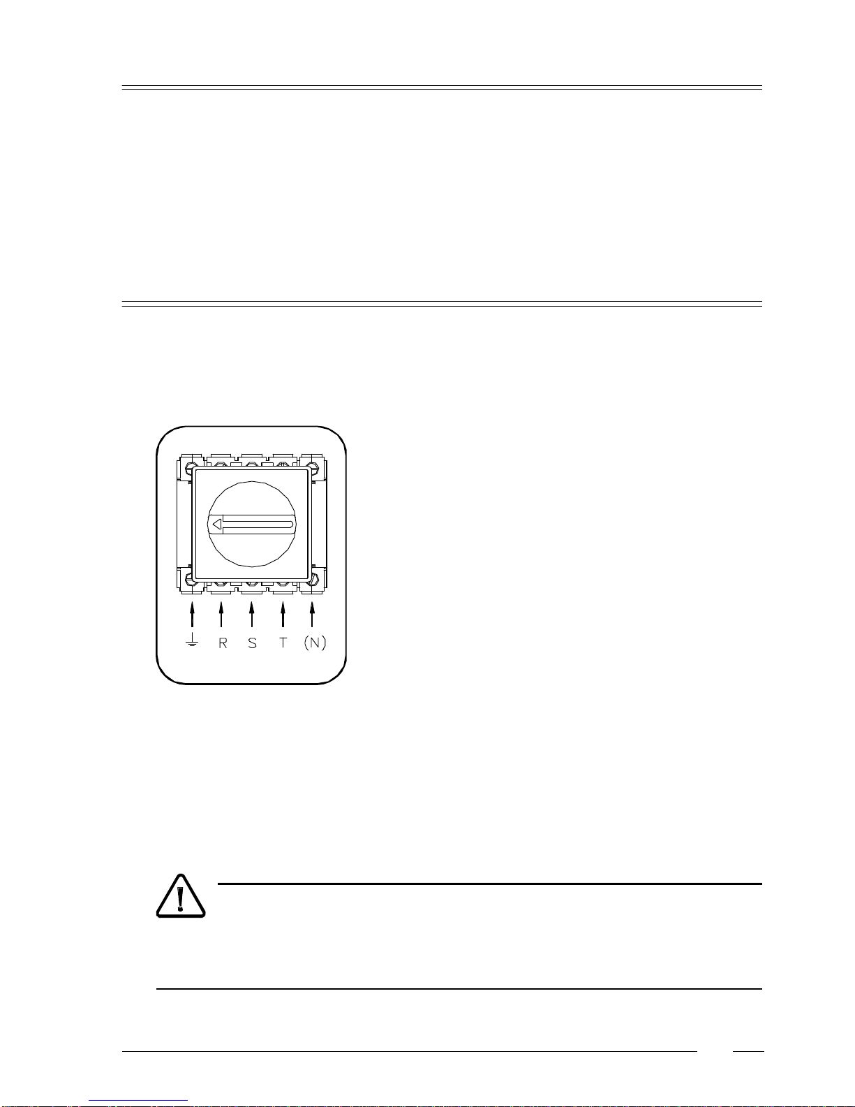
Remove the cover plate at the back of the machine (see dimensions).
ConnectthepowercabletotheconnectorsR,S,T(3x220V)orR,S,Tand
N(3x380V+N)andthegroundwire.
p
Electrical Connection
Themachineisequippedwithadrainvalvewith3"outerdiameter(80mm).
This drain valve should be connected to the drain by means of the drain
elbow which is delivered with the machine.
The diameter of the main drain should be adapted to the water flow and
the number of machines. It should be sufficient to handle at least 160L/
min.per machine.
It is necessary to connect the main drain at least on one side to an open
air-braketoallowventilation.
When the main drain has not been sufficiently deodorized, every
machine should be installed seperately with a deodorizer.
p
p
p
Water drain
p
After having connected the machine, check the spin direction of the drum. The drum should spin in the
direction of the arrowindicated on the door glass(clockwise). Ifthedrum spinsinthe wrong sense,it can
cause damage to the motor and can cause water to splash out through the soap dispenser.
In case of a wrong spin direction, switch the position of the connectors of the motor circuit from R to S
and vice versa.
Machine with electrical heating
Powerofthebreakerplugs:
220V3AC 380V3AC+N
27kW 80A 63A
36kW ---- 80A
Powerofthebreakerplugs:
220V3AC 380V3AC+N
20A 20A
Machine without electrical heating
9
3
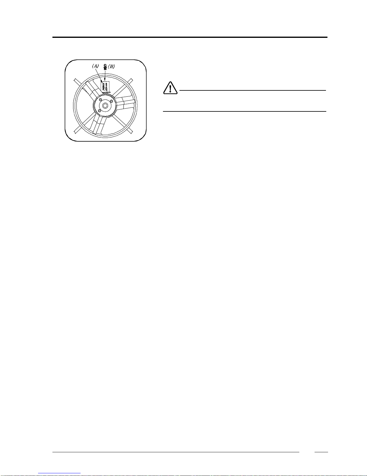
Automatic lubricator Thebearinghouse ofthemachine isequippedwith alubricatingdevice (A)
which automatically lubricates the bearing during one year. Upon delivery
ofthe machine,thislubricatorhasnotbeenbrought intouse. Tothis effect,
please put on the matching screw (B) in the foreseen opening of the
lubricator.
Ignoring this instruction will inevitably cause damage to the bearings!

10
3
S1...S5
Electrical connection of
the liquid soap pumps
The 220V can be transformed to other values to drive other type soap
pumps.
Example:pumps24V~.
A rubber connection has been placed over the air break opening at the back
of the machine. There are 5 holes in this rubber connection, through each
ofwhichaliquidsoaphosecanbedriven(S1...S5).Pressthehosesuntilthey
appear well insidethesoapdispenser.
The central gap in the rubber connection remains and serves as air breaker.
Liquid soap connection (option)
Connection of the liquid soap
hoses
On machines equipped with a liquid soap connection, connect the wires
directly on the print board next to the ground wire connection (option).
Connect as indicated on the wiring diagram.
The two connectors on the right give a tension of 220V ~ (max. 4A) which
canbeappliedtodrive220V~soappumps.Ifmorethan
4Ais required,an
external tension will have to be used. 6 connections have been provided,
of which one (S6) can be used to drive a waterproofing pump (e.g. for rain
coats, etc.).
Also, pumps with different operating tension can be combined.
Example:5pumps220V~and1pump24V~.
Withanexternaltension24V DC
This manual suits for next models
1
Table of contents
Popular Washer Dryer manuals by other brands

Whirlpool
Whirlpool WFC8090GX Use and care guide and installation instructions

Whirlpool
Whirlpool LTE5243DQ6 User instructions

Bosch
Bosch XQG100-WDU285H00W User manual and installation instructions

montpellier
montpellier MWD7512S Installation and operating instructions

LG
LG FHD0905 T Series owner's manual

Midea
Midea MF200D85B owner's manual

Maytag
Maytag MGT3800XW installation instructions

Siemens
Siemens WD15G440TR Instruction manual and installation instructions

Equator
Equator Clothes Processor EZ1500 owner's manual

Splendide
Splendide WDC7100XCP Specifications

John Lewis
John Lewis JLWD 1408 instruction manual

Ariston
Ariston A1200WD Instruction booklet


