IRIS NIghtRunner IRIS295V2 Guide

V3.00 Iss 05-06 18 - 1
IRIS295V2 / IRIS395 Installation Manual & User Guide

1.01 Conventions:
At various points within this guide, the following icons will be
used to illustrate important or potentially dangerous information:
!!WARNING
!!This symbol indicates a risk of damaging the
! ! camera or other items or an important issue that
! ! may effect the operation of the camera.
!!INFORMATION
!!This symbol points out important information
!!pertaining to the installation, operation and
! ! maintenance of the camera.
!!DANGER
!!This symbols alerts the user of a serious risk of
! ! damage or personal injury or death.
1.02 Export Regulations:
Versions of this product with a refresh rate in excess of 9Hz are
subject by European and US Export Regulations:
US Department of Commerce (DOC) Export Administration
Regulations (EAR). The Export control classification number is
6A003b4b. US Government authorization may be required for all
destination outside the US except Canada.
UK Export Controls are enforced by the UK Department for
Business, Innovations and Skills (BIS) Export Control
Organisation (ECO). These products are controlled under
classification 6A003b4b of the Dual Use Regulation. Prior
authorization is required for all exports to countries outside of
the EU and General Licenses may be available for certain
destinations.
For more information on the export regulations required for
these such devices contact Iris Innovations Ltd, Iris Innovations
USA Corporation or visit the following websites:
USA: www.bis.doc.gov
UK: www.bis.gov.uk/exportcontrol
1.03 Limited Warranty:
This product is warranted to be free from defects in materials or
workmanship for one year from the date of purchase. Upon
registration of the product an additional 12 months warranty will
be awarded FOC. Within this period, Iris Innovations will, at its
sole option, repair or replace any components that fail in normal
use. Such repairs or replacement will be made at no charge to
the customer for parts or labour, provided that the customer
shall be responsible for any transportation cost. This warranty
does not apply to: (i) cosmetic damage, such as scratches, nicks
and dents; (ii) consumable parts, such as batteries, unless
product damage has occurred due to a defect in materials or
workmanship; (iii) damage caused by accident, abuse, misuse,
water, flood, fire, or other acts of nature or external causes; (iv)
damage caused by service performed by anyone who is not an
authorized service provider of Iris Innovations Limited or Iris
Innovations USA Corporation; or (v) damage to a product that
has been modified or altered without the written permission of
Iris Innovations. In addition, Iris reserves the right to refuse
warranty claims against products or services that are obtained
and/or used in contravention of the laws of any country. This
product is intended to be used only as a travel aid and must not
be used for any purpose requiring precise measurement of
direction, distance, location or topography.
V3.00 Iss 05-06 18 - 2

Table of Contents:
Section! ! ! ! ! ! ! Page
1.01! ! Conventions! ! ! ! 2
1.02! ! Export Regulations! ! ! ! 2
1.03! ! Limited Warranty! ! ! ! 2
2.01! ! Warnings & Product Information! ! 5
3.01! ! Introduction! ! ! ! 6
3.02! ! Overview of Key Features! ! ! 6
3.03! ! Contents of Package! ! ! 6
4.01! ! Typical Configuration Examples! ! 7
5.01! ! Camera Control Data! ! ! 8
5.02! ! Cabling Requirements! ! ! 8
5.03! ! Video Connections! ! ! ! 8
5.04! ! Data Connections! ! ! ! 8
5.05! ! Connecting Multiple Cameras / Controllers!8
5.06! ! Power Connections!! ! ! 9
5.07! ! Extending Cable Length! ! ! 9
5.08! ! Setting Camera Address / Image Flip! ! 9
5.09! ! Installation Considerations! ! ! 9
5.10! ! Protocol Information!!! 9
6.01! ! Hardware Installation! ! ! 10 & 11
6.02! ! Breakout Balun! ! ! ! 12
7.01! ! Powering Up! ! ! ! 13
8.01! ! Controlling The Camera Overview! ! 13
8.02! ! Setup Features! ! ! ! 13
8.03! ! Auto-Flip Feature! ! ! ! 13
8.04! ! User Presets! ! ! ! 13
8.05! ! System Presets! ! ! ! 13
8.06! ! Scan Modes! ! ! ! 13
9.01! ! Auto-Standby Feature! ! ! 14
9.02! ! Colour Palettes! ! ! ! 14
9.03! ! ICE™ Image Contrast Enhancements! ! 14
10.01! ! Protocol Command List! ! ! 15
10.02! ! Hardware Image Flip! ! ! 16
10.03! ! Ground Loop Isolation! ! ! 16
11.01! ! Address Table! ! ! ! 17
V3.00 Iss 05-06 18 - 3

12.01! ! Camera Specifications! ! ! 18
Table of Contents: (Continued)
Section! ! ! ! ! ! ! Page
13.01! ! Appendix A - Dip Switch Settings! ! 19
14.01! ! Appendix B - Cabling Information! ! 20,21 & 22
V3.00 Iss 05-06 18 - 4

2.01 Warnings & Important Product Information
WARNING: Installation and Operation
This product must be installed and operated in accordance with
these instructions. Failure to do so may result in poor product
performance, damage to the product or vessel and or personal
injury. Installation should only be carried out be qualified
personnel or by persons competent in electrical systems.
WARNING: Power Supply and Grounding
Ensure the boats power supply is switched off during
installation. Ensure suitably rated circuit breakers / fuses are
used in the installation of the product in accordance with the
electrical values shown in the technical specifications of the
product. Never switch on power until the power connections are
correctly terminated in accordance with the information provided
in this document. Do not connect or disconnect the product with
the power supply switched on. Never disconnect the DC ground
with the power supply on.
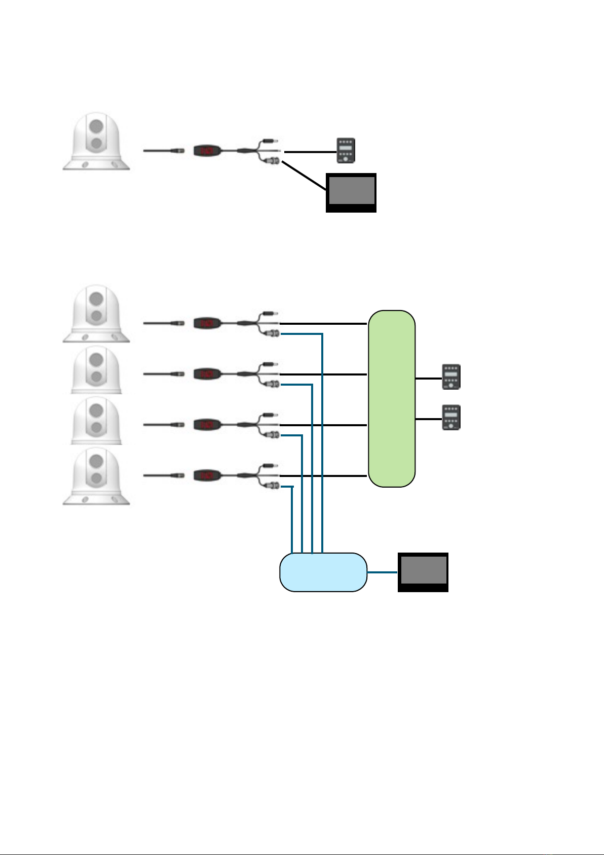
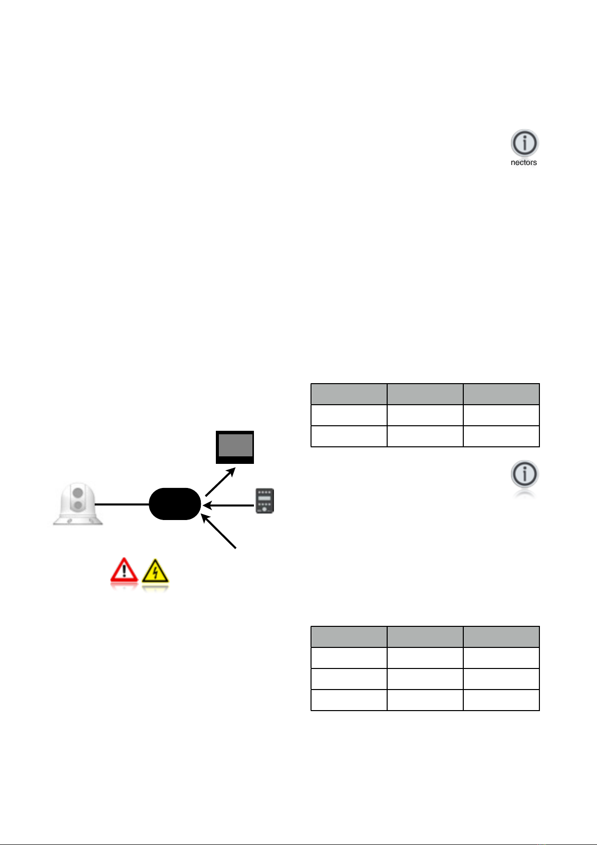
WARNING: Wiring terminations
Where the products video, power and data terminations are
extended, ensure that suitable connectors are used and that the
point of termination for each cable is adequately protected
against moisture ingress. Ensure correct polarity is strictly
observed. Do not cut or remove cable connectors without prior
permission from Iris Innovations Limited.
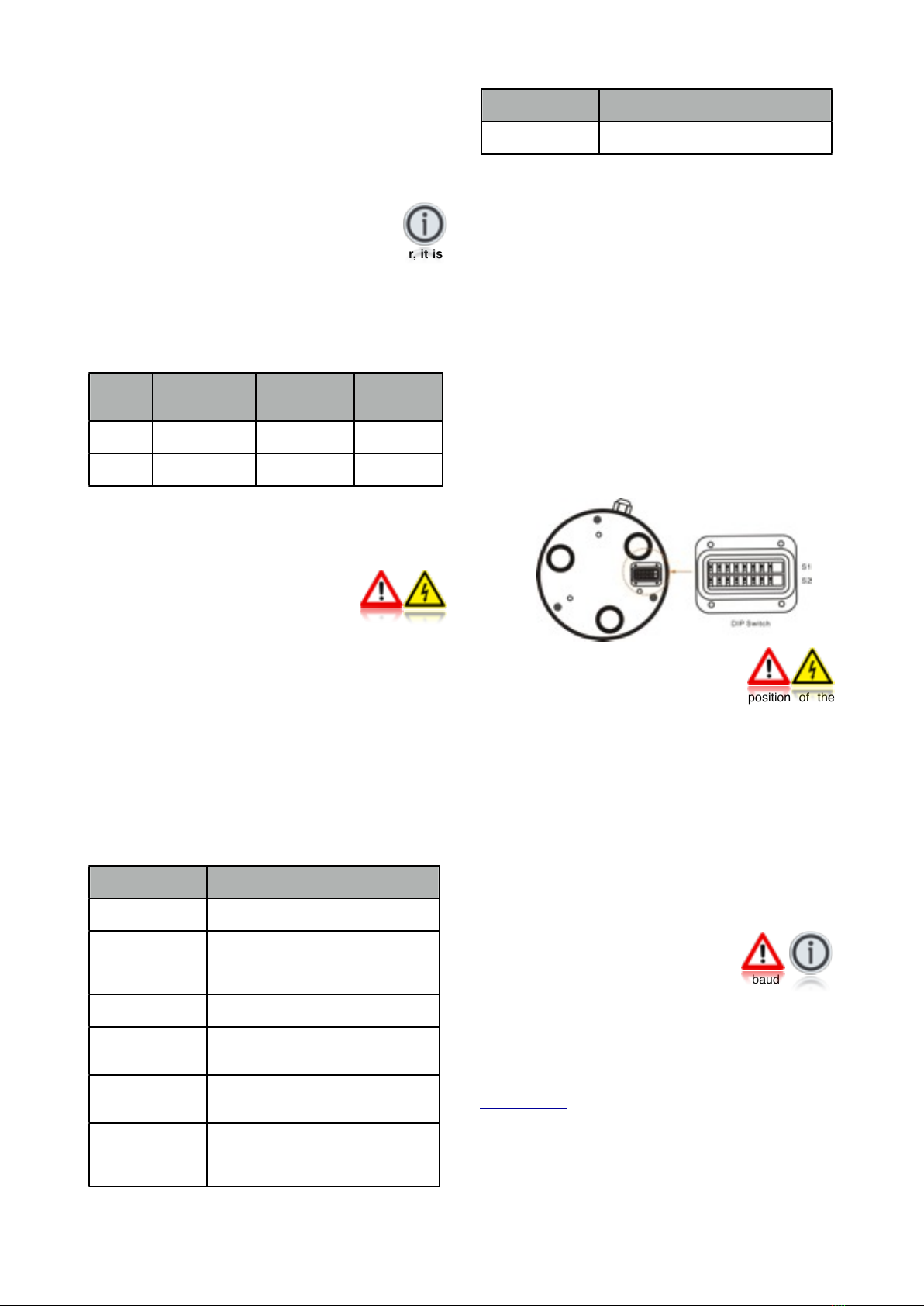
WARNING: Do Not Open the Unit
There are no user serviceable parts within the product so there s
no need to open the device other than temporarily removing the
Camera Address DIP Switch window whilst setting addresses.
Ensure the DIP switch window is correctly replaced and that the
rubber seal is not lost, pinched or damaged. The product has
been certified to IP66 standards, however, submersion or the
product or exposure to high pressure washing will invalidate the
warranty.
WARNING: Disclaimer
This product is intended to be used only as an aid to navigation
and must never be used as an alternative to correct navigational
practices and judgements made on the basis of approved
navigation methods. It is the users responsibility to observe
correct and proper navigational skill when using this product.
Only officially approved charts and notices to mariners contain
the current information required for safe navigation.
Operating the camera or viewing the video input whilst the
vessel is moving could cause a distraction and result in
accidental collision resulting in property damage, injury or death.
Iris Innovations cannot be held liable for any incidental, special,
indirect or consequential damages whether resulting from the
use, misuse or inability to use this product.
CAUTION: Switch Camera Off When Not in Use.
To prolong the operation life of the thermal cameraʼs micro-
bolometer sensor we strongly advise that power to the camera is
routed via a dedicated switch.
CAUTION: Service and Maintenance
This product contains no user serviceable parts. Please refer all
maintenance and repair issues to your authorized Iris
Innovations dealer. Any unauthoriZed work to the product may
affect the warranty.
CAUTION: Care and Cleaning
This product is a sensitive piece of electronic, imaging
equipment and must be handled and treated accordingly. Do not
drop or shake the unit during installation. Never manually alter
the pan or tilt position whilst the power to the unit is on as this
may permanently damage the motors. Avoid exposure of the
imager to direct sunlight where possible as this may degrade the
cameras performance over time.
When cleaning the device, ensure power is switched off to avoid
unintentional movement of the cameras motors. Clean the
camera housing with a soft cloth. Moisten the cloth and use a
mild detergent if required but take care not to get detergent on
the lens window. The lens window has a protective coating
which may suffer damage as a result of improper cleaning. To
clean the lens window use a soft cotton cloth. Moisten with clean
water if necessary. For further advise on cleaning the lens
window, contact Iris Innovations.
INFORMATION: Product Disposal and Recycling
Dispose of this product in accordance with the WEEE Directive.
The Waste Electrical and Electronic Equipment (WEEE)
Directive requires the recycling of waste electronic and electrical
equipment. Iris Innovations supports the WEEE policy and
politely request you observe correct disposal methods. For
further information on how to correctly dispose of this product
please contact Iris Innovations.
Please recycle unwanted packaging and documentation. The
cardboard carton, all paper manuals and documents and the
protective plastic bag in which the camera is shipped are widely
recyclable. Please check with your local recycling plant for
confirmation.
V3.00 Iss 05-06 18 - 5

3.01 Introduction
Thanks for buying NIghtRunner from Iris Innovations!
By choosing NightRunner you have added a highly sensitive
imaging device to your boat that aids visibility during the day and
perhaps more importantly, at night or in low light conditions, thus
enhancing your on board safety and enjoyment.
NightRunners Thermal Camera has a detection range of up to
2.2Km, and detecting thermal radiation rather than light, can
provide clear, detailed images in zero light conditions.
NightRunner has been especially designed for practical and
extreme operating environments such as marine, military and
emergency service vehicles.
In addition to itʼs remarkably compact and sleek design, the PTZ
is water-resistant and has anti-vibration and anti-corrosion
properties.
This document contains safety, handling, disposal and recycling
regulatory and software license information as well as the one-
year limited (and second year optional) warranty for your
NightRunner Camera. Please follow the information in this guide
and keep in a safe place for future reference.
3.02 Overview of Key Features
Hereʼs a brief list os some of NightRunners Key Features:
• 320 x 240 Vanadium Oxide Thermal Core (295)
• 640 x 512 Vanadium Oxide Thermal Core (395)
• 17µm Sensor Pitch
• <50mK NETD Thermal Sensitivity
• Hi-Resolution 700TVL Daylight Camera
•Digital Zoom on both Thermal & Daylight
Cameras.
• Colour Palettes & ICE™ Image Enhancement
• Single, user selectable camera output
• Easy to install CAT5 connection
• Ball Up or Ball Down Configuration
• Built in Mounting Bracket
• Small, stylish compact housing measures only
16cm high by 15cm in diameter.
3.03 Contents of Package
Please unpack your NightRunner and check to make sure the
following items are included. If there are any items missing
please contact your Iris dealer:
1. NightRunner Camera
2. Breakout Balun
3. 60ft Waterproof CAT5 Cable
4. 2m RG59 Coaxial Video Cable
5. BNC ~ RCA Adapter
6. In-Line Ground Loop Isolator
7. Pack of 6 1/4” x 3/” Stainless Steel Fixing Screws
8. DC Socket with Screw Terminals
V3.00 Iss 05-06 18 - 6

4.01 Typical Configuration Examples.
For single camera, single controller installs no additional hardware is required. Simply connect the IRIS595 controller directly to the data
lines of the breakout balun, and run the video from the breakout balun directly into your screen (or chartplotter etc).
If there are multiple NightRunner cameras, controllers or other PTZ cameras on the system, it will become necessary to add a serial
data distributor in order to balance the data and ensure there are no signal reflections that could result in over-runs and poor camera
control. Below is an example of a system with 2 controllers and 4 cameras. An IRISEXP0204 data expander has been used to manage
the data cables, and an IRIS604 Quad Video Switcher has been used to manage the four video feeds.
Systems can be expanded by using Serial Data Expanders to manage the control data and Video Distribution Amplifiers, Video
Switchers or Matrices to manage multiple video feeds. In addition, IP encoders can be added to enable connection over a computer
network so cameras can be viewed and controlled from smart-phones, tablets and computers.
For further information or to discuss your requirements, please contact Iris.
V3.00 Iss 05-06 18 - 7
MFD
IRIS-EXP0204
Serial Data Distributor
MFD
IRIS604
Video Switcher

5.01 Camera Control Data
NightRunner cameras are controlled via an RS485 serial data
connection, using a variant of the Pelco-D CCTV camera control
protocol. The Pelco-D protocol was designed to provide
accurate controls for a wide range of standard CCTV features,
such as pan, tilt, user preset features etc, but do not include
certain extended features supported by Iris cameras. Because
of this, Iris have mapped their product specific features to
certain user preset commands and to other modified Pelco-D
commands. This means that NightRunner cameras can be
controlled either by a dedicated NightRunner joystick controller
such as the IRIS595 or Irisʼs IRIS516 (v2), as well as other
control devices, such as compatible chart-plotters, multi-
functional displays and third party joysticks. For further
information on compatible third party control interfacing please
contact Iris Innovations. For certain third party interfacing,
additional serial protocol convertors may be required where
NMEA0183 or NMEA2000 connections are used. Details of the
Pelco-D commands mapped for Thermal Camera functions are
included in this document.
5.02 Cabling Requirements
NightRunner utilizes a unique, new cabling system designed to
simplify most installations and therefore cut cabling and install
costs.
The camera features a single, water resistant RJ45 socket into
which power, video and control data are fed via a single
waterproof CAT5 cable (supplied). An active balun adapter is
supplied to connect to the other end of the CAT5 cable. Into the
balun, DC power is fed, composite video is output and RS485
control data from the controller is fed. See Diagram Below:
WARNING!
Due to voltage drop and the associated increase in current draw,
power must be introduced no further than 50ft from the camera
when using CAT5 cable. If the 60ft CAT5 cable supplied is not
long enough, power must be run separately or taken from a
source local to where the 60ft NightRunner cable ends. See
Section 5.07 Extending Cable Length for further details.
NEVER USE CAT5 CROSS OVER CABLE WHEN RUNNING
YOUR OWN CABLE. SEE APPENDIX B FOR FURTHER
DETAILS
5.03 Video Connections
NightRunnersʼvideo output is a 1VP~P Composite video signal
compatible with most Multifunctional Displays (MFDʼs) and TVʼs
(via AV input).
The balun adapter features a male BNC connector for the video
signal, and NightRunner is supplied with a pre-made 2 meter
extension cable. Iris supply a range of pre-made extension
cables if required, alternatively, iʼve you wish to make your own
cable use 75ΩCoaxial cable such as RG59. Please note, RG59
has a solid core conductor which may not be suitable. In this
case use a stranded coaxial cable such as URM70.
A BNC ʻstraight-thruʼadapter is supplied with NightRunner in
case you need to extend the video cable run.
As well as pre-made cables, Iris supply a range of connectors,
tools and adapter plugs. Contact your Iris dealer for further
information.
Many Multifunctional Displays (MFDʼs) / Chart Plotters use RCA
(Phono) jacks for video inputs. NightRunner is supplied with a
BNC/RCA adapter for this eventuality.
5.04 Data Connections
Control commands are sent to NightRunner over an RS485
Serial Data connection which has 2 wires usually labelled either
A and B or + and -. The data wires from the NightRunner balun
are identified accordingly:
White:!RS485 A (RS485+)
Braid:!RS485 B (RS485-)
When connecting directly to an IRIS595 or IRIS516 controller,
observe the following polarity:
Balun
Function
Controller
White
RS485 A (+)
Green
Braid
RS485 A (-)
White
Note
One of the most common faults when connecting data is
incorrect polarity. In the event that there is no camera control
when you have connected up, please check the polarity of the
data wires. You cannot damage the equipment by reversing
polarity of the data wires.
5.05 Connecting Multiple Cameras / Controllers
If your system features multiple cameras and / or controllers it is
advisable to use a Serial Data Distributor. Iris supply a range of
data distributors as listed below:
Part Number
Inputs
Outputs
EXP0204
2
4
EXP0208
2
8
EXP0216
2
16
Controllers are referred to as Inputs and cameras are referred to
as outputs. If you require more than 2 controller inputs contact
Iris for details of how to configure your system.
See Page 21 for connection example diagrams.
V3.00 Iss 05-06 18 - 8
BALUN
12V / 24V DC
Power Input
IRIS595
Controller
RS485
Serial Data
60ft
CAT5 Cable
(Supplied)
IRIS295
NightRunner
MFD

5.06 Power Connections
The power tail from NightRunners balun is terminated with a
2.1mm DC Barrel plug, with a positive center pin. Connect your
DC supply to this plug using the Screw Terminal DC Socket
supplied. Always ensure your power supply is protected by a
sufficiently rated fuse or breaker. The NightRunner balun is fitted
with a 3A resettable fuse for added safety.
To prolong the lifespan of the thermal cameras sensor, it is
recommended that power to the camera is routed via a helm
mounted switch, and that the camera is switched off when
not in use.
The table below provides information on current draw depending
on the input voltage:
Input
Voltage
Consumption
(Idle)
Consumption
(Full Load)
At Cable
Distance
12VDC
1.2A
2.2A
60ft
24VDC
500mA
650mA
60ft
Details on the considerations that apply if you need to extend
the 60ft CAT5 cable supplied are listed in the section below.
5.07 Extending Cable Length
In the event that the 60ft cable supplied is not long enough, the
following considerations must be taken into account. Failure to
do so could result in damage to the camera, vessel and possibly
personal injury. Electrical connections to NightRunner must only
be conducted by fully qualified personnel.
1. On no account must a CAT5 cable longer than the 60ft cable
supplied be used to deliver power to the camera. Take power
locally to the end of the 20m cable or run a separate power
cable, suitably rated, back to the supply. Iris supply a
combined CAT5 + 2 core cable for this very purpose.
2. Video and Data can be extended further using CAT5 cable
and an additional set of baluns. Part numbers for cable
extension accessories are as follows:
Part No
Item
IRISX95-EXT-XX
Extension Kit. XX denotes cable length
CAT5-2-XX
CAT5 Cable + 2 Cores for Extending
DC Supply. ʻXXʼdenotes desired
length in meters.
BALX95
NightRunner Balun (Individual)
IM-POW-XX
DC Power Cable (50V, 5A). ʻXXʼ
denotes desired length in meters
IM-BNC-XX
75ΩRG59 Coaxial Cable (BNC~BNC)
Video Extension Cable.
IM-DAT-XX
Single Twisted Pair Data Cable for
RS485 Control. ʻXXʼdenotes desired
length in meters.
Part No
Item
BNC-THRU
Straight Thru BNC Adapter
3. The diagram in section 6.03 illustrates methods of
extending the cabling.
5.08 Setting Camera Address / Image FLIP
Each camera must have itʼs own unique address so that only
control data intended for that camera is received and processed
by the camera. If multiple cameras had the same address, they
would all move together when pan and tilt commands are
transmitted.
To set the camera address, remove the DIP switch cover plate
on the base of the camera with a small cross-head screw driver,
taking care not to loose the 4 screws or the rubber ʻOʼseal, and
set the DIP switches on switch bank 1 accordingly. A table
detailing the switch settings can be found at the end of this
document and further details in Appendix A (Page 19)
Once the desired address has been set, carefully replace the
DIP switch cover plate.
Switch No.8 on bank S1 will also set the image orientation. See
section 10.02 Hardware Image Flip for details.
5.09 Installation Considerations
It's important to fully consider the intended position of the
camera and the desired fields of view prior to installation, in
terms of how you are going to get cables to the position, will the
camera be able to see the appropriate areas, will the camera
interfere with any other fixture such as a doorway or walkway
once it's fixed in place, or are there any obstructions behind the
surface onto which the camera is to be installed. It's strongly
recommended that if possible the camera should be temporarily
powered up prior to final installation and offered into position so
that these factors can be considered and any possible issue can
be addressed before holes are drilled and difficult, time
consuming and costly cable runs are attempted. Check third
party hardware to ensure it doesn't effect the operation of the
camera and vice versa.
5.10 Protocol Information
DIP switch bank 2 is reserved for setting the baud rate and
protocol details. This is factory set to 9600 Baud, Pelco-D
Protocol, N-8-1 (No Parity Bits, 8 Data Bits, 1 Stop Bit). Do not
attempt to change these settings as they are locked. Changing
the settings of Switch bank 2 could result in the camera not
responding to data commands.
Full details of the Pelco-D control protocol can be found at
www.pelco.com.
As well as the standard Pelco-D command set, Iris cameras use
their own commands based on the Pelco protocol to call
features that are specific to the model or are not covered by the
Pelco command set. A list of these features is included later in
this document. For further details contact Iris Innovations.
V3.00 Iss 05-06 18 - 9

6.01 Hardware Installation
Get to know your NightRunner!
The different parts of your camera are labelled here:
Once youʼve established a suitable fixing position, offer the
camera into place to mark off the six Surface Fixing Positions
and the cable clearance position.
The camera is supplied with 6 x Stainless Steel, 1/4”x3/4” self
tapping screws. Drill pilot holes accordingly and use a 30mm
hole saw to create the cable entry hole.
When the CAT5 cable is correctly terminated (see next section),
offer the camera up into the fixing position and firmly screw into
place.
Observe extreme caution when siting the camera. Ensure the
act of drilling the pilot holes and cable entry hole does not
infringe any cables, equipment or fixtures behind the panel onto
which the camera is to be installed.
To avoid moisture ingress between the bottom of the camera
and the surface onto which the camera is to be attached, apply
a bead of suitable silicone sealant around the edge of the plate
to create a seal.
V3.00 Iss 05-06 18 - 10
Daylight Camera Lens Window
Protective lens window for daylight camera.
Germanium Lens Window
Protective lens window through
which heat is conducted. This is
manufactured through a material
called Germanium - not glass.
Thermal Imaging cameras cannot
ʻseeʼthrough glass.
Inner Dome
Contains the thermal camera
module and tilt motor
Protective Cowling
Shields the Inner Dome and Tilt
Pivot points
Base Section
Contains the telemetry
data circuitry and Pan
motor
DIP Switch Window
Protects switches for Camera
Address and other features.
Camera Connector
Waterproof RJ45 Connector for camera
Power, Video & Data.
Base Plate
Do not remove. Protects pan motor and
telemetry data circuitry.
Fixing Points
1/4” Clearance holes in six positions for
fixing camera in place.
IRIS295 Thermal Imaging / Daylight Dual Payload PTZ Camera in Standard (Desktop) Orientation.
This style of housing is known as the NightRunner Series Housing.

6.01 Hardware Installation (Continued...)
1. Once youʼve established a suitable installation position, offer the camera in to place and mark of the six fixing holes. Alternatively, use
the drilling template supplied to mark of the fixing positions and cable entry hole.
2. Use a suitably sized drill to create pilot holes for the 6 x 1/4”x3/4” fixing screws.
3. Use a 35mm hole saw to create the cable entry hole
4. Apply a thin bead of water resistant marine silicone around the rim of the camera base to prevent water ingress through the screw
holes and cable entry point.
5. Pass your cable through the cable entry hole and connect to the base of the camera, ensuring the waterproof back shell is fully
tightened and not cross threaded.
6. Position the camera as desired and fix into place with the 6 x 1/4”x3/4” fixing screws. Loosely tighten each of the six screws so the
camera is in the correct position and then fully tighten each screw until secure. Make sure you do not over-tighten. If whilst fixing the
cameras it becomes difficult to tighten a screw, or the GRP shows signs of stress, remove the screw and carefully open out the pilot
hole slightly to relief the stress.
V3.00 Iss 05-06 18 - 11

6.02 Breakout Balun
The 60ft CAT5 cable from your NightRunner terminates in the supplied Breakout Balun thatʼs pictured below.
6.03 Details on Extending Cable
As described in section 5.07 Extending Cable Length, if you need to extend the cable run, you must not run power along the CAT5
cable . Either apply the power local to the end of the 50ft cable supplied or run the power separately. See diagram below:
Option 1:
The IRISX95EXT-XX kit contains all you need to extend the cable run. The XX in the part number denotes the desired length in
multiples of 5 meters. The cable itself is CAT5 cable with an additional 2 cores for power. All the necessary connectors and adapters are
provided to enable plug and play installation.
Option 2:
Alternatively, it might be possible to connect to a power source close to the end of the 20m CAT5 supplied. In this instance, use the
extension kit for the video and data signals.
V3.00 Iss 05-06 18 - 12
Power Supply
2.1mm DC Barrel Connector.
RS485 Data Wires
Connect to your IRIS595 Controller or
other control option.
Video Output
75Ω1VP~P Composite Video
Input from Camera
CAT5 (B) RJ45 Connector
NightRunner
17m NightRunner Cable
Breakout Balun
Extension Kit
(2 x Baluns, CAT5+2 Cable, BNC~BNC
Thru-Adapter, Screw-On DC Power Jack.)
Option 1: Extension Kit
Option 2: Power from Local Source
RJ45 Connector
Connect into socket.

7.01 Powering Up
Upon switching on the circuit breaker that isolates the camera,
the unit will perform an initialization routine. During this routine,
which lasts approximately 30 seconds, the camera will pan and
tilt automatically in order to calibrate itself. You will notice the
mechanical shutter 'wiping' the image frequently for the first few
minutes as the unit warms up. This will eventually settle into an
automatic interval of wiping approximately every couple of
minutes. This only lasts for a fraction of a second and allows the
camera to calibrate itself for the best possible image in
accordance with the ambient temperature.
Never apply power to the camera unless all connections are
terminated correctly. Never disconnect the DC ground for
any reason whilst the camera is powered up as this could
result in damage to the electronic circuitry.
When the camera has completed its boot-up routine, a text
overlay table will appear in the screen displaying the camera
address, protocol, baud rate and current firmware version. You
will also notice the positional indicator icon in the bottom left
hand corner of the screen and the zoom bar at the center
bottom of the screen. When this message appears the camera
is ready to use and you are able to control the device.
8.01 Controlling the Camera - Overview
Your camera features positional controls and extended features.
Positional features such as Pan, Tilt and Zoom are usually
controlled via a compatible joystick controller, such as the
IRIS595 or IRIS516 controllers or via a compatible MFD / Chart-
Plotter - sometimes via touch-screen controls depending on the
make and model. Third party control methods may differ from
Iris controllers. For details of compatible third party control
interfaces please contact Iris Innovations. Control of extended
features depends on the type of controller you are using, but is
usually accessed via a menu system on the controller or third
party device (MFD / Chart-plotter etc). If using a third party
control interface consult the relevant user documentation for the
specific equipment for details.
A list of feature commands is included at the end of this
document.
8.02 Set-Up Features
The following features will only usually be called during the initial
set-up of the camera following installation and are accessed
through the MENU function detailed below.
• Video Orientation
!UP / DOWN / UP+MIRROR / DOWN+MIRROR
Setting the vertical orientation (UP or DOWN) is determined by
the orientation of the camera (Standard = UP / Hanging (also
known as Ball Down) = DOWN). The mirror option is usually
only used when the camera is facing aft, and is usually only
applied to fixed cameras, as with a PTZ camera such as
NightRunner, the camera pan position is frequently changing.
Video orientation can however easily be ʻflippedʼas required
with the IRIS595 or IRIS516 controller.
• Set Home Position
!
This feature lets you set the home position of the camera
following install. Usually this is aligned with the bow of the boat.
This calibrates the positional indicator with the direction of the
camera.
8.03 Auto-Flip
When the camera is tilted past its azimuth the Auto-Flip feature
is triggered. This automatically pans the camera through 180˚ at
full speed (Proportional Control is disabled during this
procedure) to the original pan position and continues the tilt
movement as long as the camera is still being tilted. This
corrects the orientation of the camera module as if the unit kept
tilting past the azimuth without the automatic correction, the
module would be upside down.
8.04 User Presets
The camera has a built in memory that can be used to store up
to 100 user ʻpresetʼpositions. A preset allows you to move the
camera to a favourite or important position and learn that
position so that the camera can be instructed to move at top
speed to that position at the touch of a button. For example, you
may want to point the camera so that itʼs facing directly aft so
you can take a look at whatʼs coming up behind you. By saving
this position as a Preset, you can send the camera back to this
position immediately by recalling the preset. Presets can also be
used to form ʻToursʼ, where the camera can be instruction to
step through each preset within the Tour in sequence with a pre-
determined dwell time between each position.
User presets are numbered 1-100. Usually the controller you are
using will have the ability to SET a Preset to learn the position
and then CALL a Preset to send the camera to that position.
This will depend on the model of controller you are using.
Consult the user guide of your controller for details.
8.05 System Presets
Certain functions of the camera that are not defined by the
Pelco-D Protocol are called by using Presets. A list of System
Presets can be found later in this document.
8.06 Scan Modes
The camera supports 4 different Scan Modes. Once activated,
tilt and zoom commands are still accepted by the camera but
you will not be able to pan the camera until the Scan has been
Stopped:
• 45˚ Auto Scan
!Camera pans back and forth 22.5˚ either side of the
!centre point (the position the camera is facing when the
!scan is activated.
• 90˚ Auto Scan
!Camera pans back and forth 45˚ either side of the
!centre point (the position the camera is facing when the
!scan is activated.
• 180˚ Auto Scan
!Camera pans back and forth 90˚ either side of the
!centre point (the position the camera is facing when the
!scan is activated.
• 360˚ Auto Scan
!Camera pans continuously through 360˚, pausing every
!108˚.
There are three speed controls for each Scan. Slow, Medium
and Fast. A command is also available to ʻRe-Centreʼthe scan.
This can be found in the command list.
V3.00 Iss 05-06 18 - 13

9.01 Auto-Standby Feature
As well as the manual standby function, NightRunner also
features an automatic standby which will operate if the camera
has not received a control command after a period of one hour.
Immediately prior to the camera going into auto-standby, a
message will be displayed on the screen informing the user that
the camera is going to sleep. To prevent the camera going into
standby mode, simply nudge the joystick, or from a third party
control device, send the camera any control command. This will
re-set the timer. If a control command is not received after 60
seconds, the camera will proceed to go into standby mode,
during which the inner dome will tilt down into the base of the
camera and switch off the power to each camera module.
Auto Standby is intended as a power-save and safety feature to
prolong the operational life of the product.
9.02 Colour Palettes
The IRIS295v2 & 395 features 12 colour palettes grouped 2 per
button on the 595 controller as list below:
• Button 1 - ʻHOTʼ- (Black Red / Red Hot)
• Button 2 - ʻBlueʼ- (Blue Green Red / Rainbow 1)
• Button 3 - ʻWarmʼ- (Blue Red Yellow / Purple Red
Yellow)
• Button 4 - ʻGreyʼ- (White Hot / Black Hot)
• Button 5 - ʻMixʼ- (Black Green Red / Mixed)
• Button 6 - ʻR.Bowʼ- (Rainbow 2 / Black Green Red-Pink)
Colour palettes have been grouped to provide the most logical
pairing.
9.03!ICE™ Image Contrast Enhancement
All NightRunner cameras feature Irisʼs incredible new ICE®
Image Contrast Enhancement feature, which processes each
image pixel individually in order to provide digital edge
enhancement in scenes of a low thermal contrast, dramatically
boosting the detail in an otherwise flat image.
With all thermal imaging cameras, if the thermal scene is flat (ie,
similar temperature), the image may not appear as sharp as it
could be. With Irisʼs ICE™ feature enabled, each pixel is
analyzed and where there are distinct differences in pixel colour,
the cameras processor accentuates the contrast in order to
provide a much more defined and clearer image.
There are seven user definable levels of ICE™ processing, with
level 1 being the default, non-processed, image, and 7 being the
highest level of processing.
V3.00 Iss 05-06 18 - 14

10.01 Protocol Command List
The table below lists features specific to IRIS295 Series (NightRunner) Cameras that are not covered by the standard Pelco-D protocol
and the commands that have been mapped in IRIS camera software to operate those features. Values are shown in hexadecimal. The
checksum for all Pelco-D commands is the 8 bit (modulo 256) sum of the payload bytes (bytes 2 ~ 6) within the message. Refer to the
Pelco-D protocol document for further information.
For more in depth information on Iris Protocol mapping please contact Iris Innovations.
V3.00 Iss 05-06 18 - 15
Function
Command
H
Add
C1
C2
D1
D2
CHK
Flip Ball Up
Preset 236
FF
AD
00
07
00
EC
CHK
Flip Ball Down
Preset 239
FF
AD
00
07
00
EF
CHK
Flip Ball Up Mirror
Preset 237
FF
AD
00
07
00
ED
CHK
Flip Ball Down Mirror
Preset 238
FF
AD
00
07
00
EE
CHK
Black Hot / Colour Camera
Preset 202
FF
AD
00
07
00
CA
CHK
White Hot / Inverse Camera
Preset 201
FF
AD
00
07
00
C9
CHK
Ocean Blue Scale
Preset 217
FF
AD
00
07
00
D9
CHK
Ocean Blue Scale Invert
Preset 218
FF
AD
00
07
00
DA
CHK
Inferno / Hot
Preset 213
FF
AD
00
07
00
D5
CHK
Inferno / Hot Invert
Preset 214
FF
AD
00
07
00
D6
CHK
Blue Green Red
Preset 205
FF
AD
00
07
00
CD
CHK
Rainbow 1
Preset 206
FF
AD
00
07
00
CE
CHK
Rainbow 2
Preset 207
FF
AD
00
07
00
CF
CHK
Black Red
Preset 208
FF
AD
00
07
00
D0
CHK
Black Green Red
Preset 209
FF
AD
00
07
00
D1
CHK
Black Green Red/Pink
Preset 210
FF
AD
00
07
00
D2
CHK
Mixed
Preset 211
FF
AD
00
07
00
D3
CHK
Red Hot
Preset 212
FF
AD
00
07
00
D4
CHK
Full Spectrum
Preset 215
FF
AD
00
07
00
D7
CHK
Full Spectrum Invert
Preset 216
FF
AD
00
07
00
D8
CHK
Blue Red Yellow
Preset 203
FF
AD
00
07
00
CB
CHK
Purple Red Yellow
Preset 204
FF
AD
00
07
00
CC
CHK
Daylight Camera Select
Preset 226
FF
AD
00
07
00
E2
CHK
Thermal Camera Select
Preset 229
FF
AD
00
07
00
E5
CHK
Standby
Preset 231
FF
AD
00
07
00
E7
CHK
Wake Up
Preset 230
FF
AD
00
07
00
E6
CHK
ICE Decrease Level by 1
Preset 253
FF
AD
00
07
00
FD
CHK
ICE Increase Level by 1
Preset 254
FF
AD
00
07
00
FE
CHK
Factory Reset
Preset 255
FF
AD
00
07
00
FF
CHK

10.02 Hardware Image Flip
As well as storing the cameras address, the DIP switches in the base of the camera also control the camera orientation.
Switch 8 on bank S1 should always be set to ON. This enables the camera orientation memory so that on bootup, the camera will
always revert to the last position stored in memory.
Ordinarily, the cameraʼs orientation will only ever be changed during install. For example, if the camera is installed in the hanging
orientation, the installer will use the IRIS595 MENU system to select the correct orientation. This will now be stored in memory and as
long as Bank S1 Switch 8 is set to ON, the camera will read this position on boot-up and set the orientation accordingly.
10.03 Ground Loop Isolator
For situations when the DC ground and Video Ground of your monitor are common, the CAT5 / Balun wiring method may introduce a
ground loop onto the video which manifests as interference / ghosting on the video image.
To counter this, an in-line Video Ground Loop Isolator is included with your NightRunner. This may also help with other kinds of video
interference which are induced by proximity of power cables, and other general noise and interference issues.
In the event that such noise is present on your video image, connect the Ground Loop Isolator in line with the coaxial video cable from
the output of your breakout balun - observing the polarity marked on the body of the device.
V3.00 Iss 05-06 18 - 16

11.01 Camera Address Table
The cameras unique device address is set using DIP switch Bank 1. The following table lists switch positions for each address from
0~38. There are a total of 255 address positions available. For address settings above 38 please contact Iris Innovations technical
support.
Do not use address 0 as this is rarely used by control equipment.
V3.00 Iss 05-06 18 - 17
ADDRESS
1
2
3
4
5
6
7
8
0
OFF
OFF
OFF
OFF
OFF
OFF
OFF
OFF
1
ON
OFF
OFF
OFF
OFF
OFF
OFF
OFF
2
OFF
ON
OFF
OFF
OFF
OFF
OFF
OFF
3
ON
ON
OFF
OFF
OFF
OFF
OFF
OFF
4
OFF
OFF
ON
OFF
OFF
OFF
OFF
OFF
5
ON
OFF
ON
OFF
OFF
OFF
OFF
OFF
6
OFF
ON
ON
OFF
OFF
OFF
OFF
OFF
7
ON
ON
ON
OFF
OFF
OFF
OFF
OFF
8
OFF
OFF
OFF
ON
OFF
OFF
OFF
OFF
9
ON
OFF
OFF
ON
OFF
OFF
OFF
OFF
10
OFF
ON
OFF
ON
OFF
OFF
OFF
OFF
11
ON
ON
OFF
ON
OFF
OFF
OFF
OFF
12
OFF
OFF
ON
ON
OFF
OFF
OFF
OFF
13
ON
OFF
ON
ON
OFF
OFF
OFF
OFF
14
OFF
ON
ON
ON
OFF
OFF
OFF
OFF
15
ON
ON
ON
ON
OFF
OFF
OFF
OFF
16
OFF
OFF
OFF
OFF
ON
OFF
OFF
OFF
17
ON
OFF
OFF
OFF
ON
OFF
OFF
OFF
18
OFF
ON
OFF
OFF
ON
OFF
OFF
OFF
19
ON
ON
OFF
OFF
ON
OFF
OFF
OFF
20
OFF
OFF
ON
OFF
ON
OFF
OFF
OFF
21
ON
OFF
ON
OFF
ON
OFF
OFF
OFF
22
OFF
ON
ON
OFF
ON
OFF
OFF
OFF
23
ON
ON
ON
OFF
ON
OFF
OFF
OFF
24
OFF
OFF
OFF
ON
ON
OFF
OFF
OFF
25
ON
OFF
OFF
ON
ON
OFF
OFF
OFF
26
OFF
ON
OFF
ON
ON
OFF
OFF
OFF
27
ON
ON
OFF
ON
ON
OFF
OFF
OFF
28
OFF
OFF
ON
ON
ON
OFF
OFF
OFF
29
ON
OFF
ON
ON
ON
OFF
OFF
OFF
30
OFF
ON
ON
ON
ON
OFF
OFF
OFF
31
ON
ON
ON
ON
ON
OFF
OFF
OFF
32
OFF
OFF
OFF
OFF
OFF
ON
OFF
OFF
33
ON
OFF
OFF
OFF
OFF
ON
OFF
OFF
34
OFF
ON
OFF
OFF
OFF
ON
OFF
OFF
35
ON
ON
OFF
OFF
OFF
ON
OFF
OFF
36
OFF
OFF
ON
OFF
OFF
ON
OFF
OFF
37
ON
OFF
ON
OFF
OFF
ON
OFF
OFF
38
OFF
ON
ON
OFF
OFF
ON
OFF
OFF

12.01 Technical Specifications
Dimensions
160mm High x 172mm Diameter
Weight
1.4KG
1.4KG
Material
UV Stabilized ABS Plastic Housing. Anodized Aluminum Base Plate
Pan Movement
Range: 360˚ Continuous Rotation
Speed: 0.05~70˚/Sec ~ 0.05~240˚/Sec
Max
Tilt Movement
Range 200˚ with Auto-Tilt at azimuth
Speed: 0.03~38˚/Sec ~ 0.05~140˚/Sec
Max
Fixings
6 x 1/4” x 3/4” 316 Stainless Steel Pozi Screws, Self Tapping (Supplied)
Connections
RJ45 Socket - Waterproof Screw Type Seal. IP66. 50ft CAT5 Cable Supplied
Power Consumption
12/24VDC (min=9V / Max=30V)
Consumption: 1.2A Idle, 2.2A Max @ 12V
Video Output
1V P~P Composite Video Output / 75ΩImpedence
Synchronization
Internal
Internal
Temperature Range
-30 ~ +50˚C
-30 ~ +50˚C
Environmental
IP66
IP66
Thermal Core - IRIS295V2
17µm 384x288 Uncooled Vanadium Oxide (VOx) Long Range Infra Red Core
Thermal Core - IRIS395
17µm 640x512 Uncooled Vanadium Oxide (VOx) Long Range Infra Red Core
Thermal Attributes
8~14µm Spectral Band / Thermal Sensitivity <50mK
Video Format
NTSC: 480i @ 30HZ
PAL: 576i@25HZ
Thermal Refresh Rate
60Hz
60Hz
Thermal Palette Control
12 Palettes
12 Palettes
Digital Zoom Control
Thermal: 1~4x (32 Steps)
Daylight: 1~10x (255 steps for smooth
zoom)
Daylight Camera Imaging Device
1/3” SONY Super HAD CCD II Sensor (960H Double Speed CCD)
Picture Elements
NTSC: 976 x 494
PAL: 976 x 582
Resolution
700TVL
700TVL
Lens Option
Thermal: 19mm (295v2) / 25mm (395)
Daylight: 12mm
Mirror Imaging
Thermal: OFF / V-Flip / H-FLIP / VH-Flip
Daylight: OFF / V-Flip / H-FLIP / VH-Flip
Digital Image Stabilization
Thermal: ON
Daylight: ON
Wide Dynamic Range
Thermal: ON
Daylight: ON
Digital Noise Reduction
Thermal: ON
Daylight: ON
Gain Control
Thermal: Automatic
Daylight: Automatic
Serial Data Connection
RS485 / Pelco-D (Extended Features Accessed via Iris Variant)
Shock and Vibration
IEC60945 MIL STD 810E
Sand and Dust
IEC60945 MIL STD 810E
APPENDIX: A
V3.00 Iss 05-06 18 - 18

DIP SWITCH SETTINGS
Its vitally important to ensure the DIP switch settings for your camera are correct. Incorrect settings could result in issues such as video
loss or no control.
When you open the DIP switch window, hold the camera so the switches are orientated as shown below.
Switch Bank 1
The top bank of switches is Switch Bank 1 and controls the video format (switch 3) and image flip (switch 8). You should never need to
touch switch bank 1 as it is factory set depending on your region. Switch 3 sets PAL/NTSC, switch 8 sets the cameras memory to
remember image flip commands sent from the IRIS595 controller and also flips image when set from OFF to ON).
Switch Bank 2
The bottom bank of switches is Switch Bank 2. This sets the cameraʼs address between 01 and 255 in binary. Therefore, switch 1 has
the value of 1 when it is in the ON position, switch 2 has the value of 2, switch 3 has the value of 4, switch 4 has the value of 8 and so
on. A table showing the correct address settings from Address 1 to Address 38 is provided as an example on page 17.
Example 1
The example below shows the camera set to NTSC (Bank 1, Switch 3 = ON), Image flip memory ON(Bank 1, Switch 8) and address 5
(Bank 2, switches 1 and 3 - ie, switch 1 = value 1, switch 3 = value 4, therefore 1+4=5.
Example 2
The example below shows the camera set to NTSC (Bank 1, Switch 3 ON), Ball Down (hanging) orientation (Bank 1, Switch 8 = ON),
and address 1.
WARNING!
The settings for Bank 1 switches 1~7 are factory set and should never be changed! Changing these settings can seriously effect the
performance of your camera.
V3.00 Iss 05-06 18 - 19
SW1
SW2
SW1
SW2
SW1
SW2
When Bank 1 Switch 8 is set from
OFF to ON the video output will
flip to the ʻball downʼorientation
and the cameras memory will be
activated. This stores any
subsequent image flip command
sent from the IRIS595 controller.

APPENDIX: B
CABLING
NightRunner is supplied with a 50ft water resistant CAT5 568B Straight-Thru Cable.
WARNING!
Although CAT5 cable is utilized, NIGHTRUNNER IS NOT A NETWORK DEVICE AND MUST NEVER BE CONNECTED TO
ETHERNET EQUIPMENT SUCH AS SWITCHES, ROUTERS, PoE INJECTORS etc.
Connecting to such devices could damage the camera beyond economical repair and also damage the IRIS595 controller and any other
equipment that may be on the network.
If the supplied cable is not long enough, contact your Iris dealer for information on our cable extension kits.
If you need to shorten the cable, please ensure the correct termination polarity is observed as shown below. Remember, NightRunner
has a Straight-Thru CAT5 568B cable.
WARNING!
NEVER USE A CAT5 CROSS OVER CABLE AS THIS WILL CAUSE PERMANENT DAMAGE TO YOUR CAMERA AND IRIS595
CONTROLLER. BOTH ENDS MUST BE TERMINATED AS SHOWN BELOW:
V3.00 Iss 05-06 18 - 20
PIN NUMBER
WIRE COLOUR
FUNCTION
1
White / Orange
DATA+
2
Orange
DATA-
3
White / Green
DC GND
4
Blue
DC+
5
White / Blue
DC GND
6
Green
DC+
7
White / Brown
VIDEO SIGNAL
8
Brown
VIDEO GND
This manual suits for next models
1
Table of contents
Other IRIS Thermal Camera manuals