Ironmaster Super Bench Quick reference guide
Assembly & Operating Instructions
Ironmaster Super Bench
Congratulations on your purchase of this fine Ironmaster product. Be sure to read and understand the
operating instructions to achieve the best performance and avoid injury.
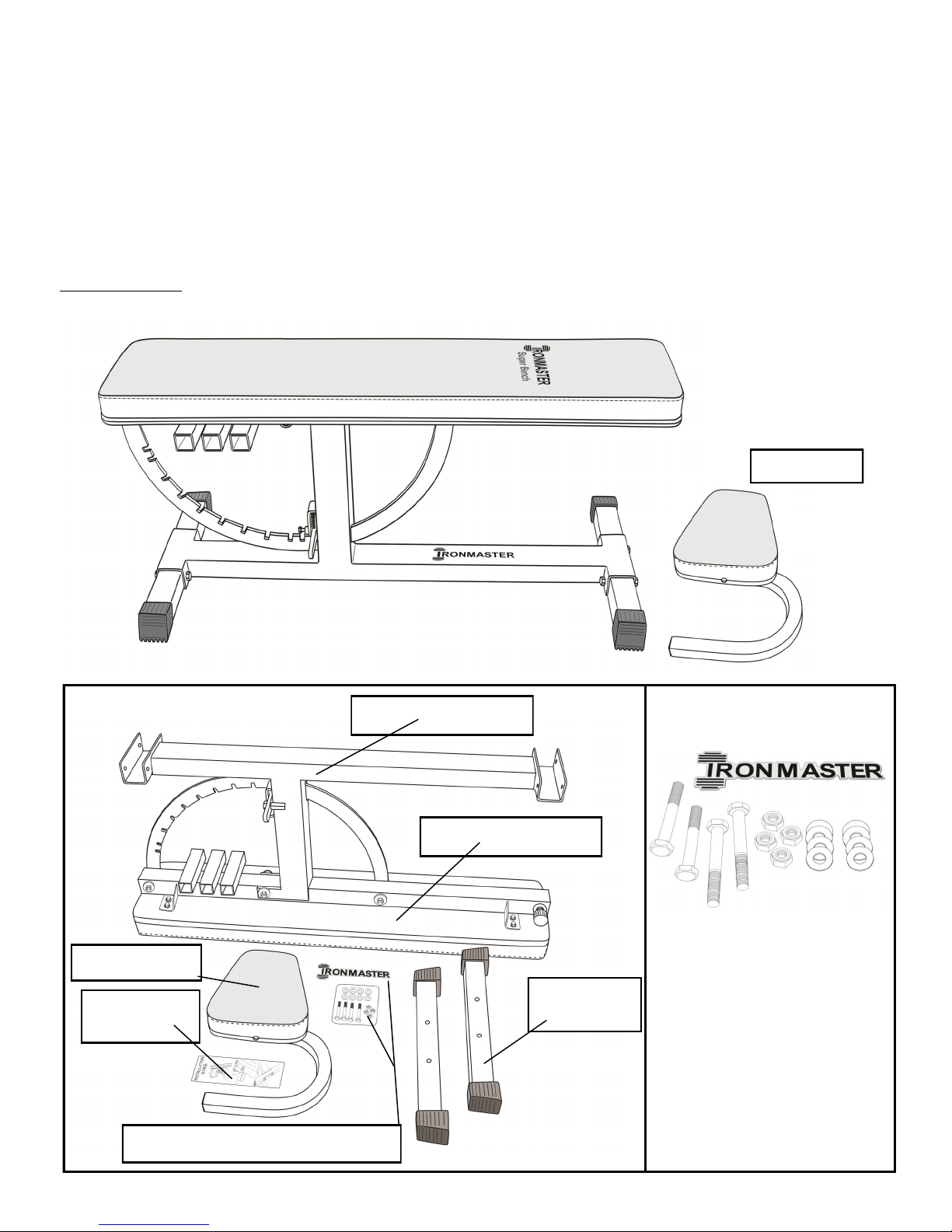
1x Ironmaster Emblem
4x M10 x 70mm Hex Bolts
4x M10 Nylock nuts
8x M10 Washers
NOTE:
2x 17mm box wrench or
Ratchet wrench (Not included)
required for assembly
2x Super
Bench Foot
1x Incline Seat
1x Super Bench frame
Box Contents:
1x Bolt Pack and Ironmaster Emblem
Bolt Pack Contents:
Bench Main Pad
1x Instruction
manual
Description:
This adjustable exercise bench is designed to be used for dumbbell training, in a rack or cage for barbell training, or with
many various optional attachments. It is a heavy duty multi use bench with 11 angle positions and includes a removable
incline seat. Some tools are required for assembly as indicated in the following steps. The maximum load capacity
including the user is 1000 LBS/450 KGS in the flat position and 600 LBS/270 KGS when tilted or the incline seat is used.
Incline Seat

Assembly:
1. Remove contents from box. Find bolt pack.
2. Remove foot support tubes from main frame and
discard. Please recycle.
3. Install foot while bench is upside down for convenience
but do not tighten. 2x M10 x 70mm bolts 4x M10 Wash-
ers and 2x Nylock Nuts.
4. Repeat process with remaining foot. Do not tighten.
5. Turn Super bench upright and tighten bolts securely,
and retighten once assembly is complete. Tighten bolts
on level surface only to assure the bench is level. Bolt ten-
sion of 40ft lbs recommended.
6. Remove backing from Ironmaster Emblem and install as
shown below.
NOTE: Assembly requires 2x 17mm wrenches (Not
included).
Operation:
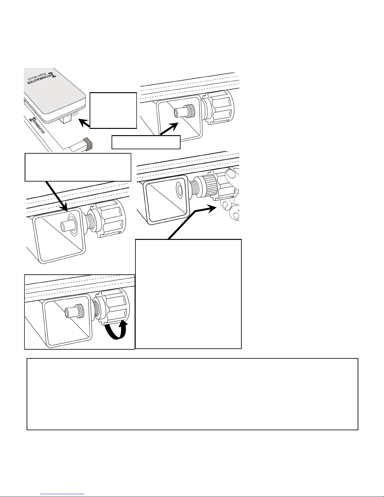
Be sure the locking lever enters the locking ring notches completely before using the bench. To adjust, lift the locking
lever and move the bench to any of the 11 desired angles and lock lever into position. The incline seat simply plugs in
from the side into position. There are three choices of plug ins available to best match height/comfort of user.
CAUTION: Keep fingers clear of locking lever where it engages with the locking ring.
CAUTION: Make sure locking lever seats completely into any of the 11
positions within the locking ring. Failure to locate properly my result in the
locking lever slipping out of position during use. If the locking ring cannot
locate correctly please see instructions right. Should these adjustments
fail to solve the problem, discontinue use and contact Ironmaster for
further assistance.
The Super Bench can be set to 11 angles: 0, 5, 10, 20, 30, 40, 50, 60, 70, 80, and 85 degrees.
Tighten securely once
both feet are installed
M10 Washer and M10
Nylock Nut on inside of
frame
Install M10 X70mm bolt
and M10 Washer from
outside
For further details regarding the Super Bench, operation, use with accessories, tutorials and
video links, please visit our website at www.ironmaster.com
First, locate the Pull pin at the front of
the frame under the main bench pad.
To operate, turn the pin counter clock-
wise until you are able to pull the pin
against the spring (note if you contin-
ue to turn, the entire Pull pin assembly
will come out of the Super Bench
frame).
It is recommended to unthread the pin
once or twice to familiarize yourself
with how many turns it takes to disen-
gage the threads but keep the pull pin
barrel inside the frame before using
any accessories.
When used correctly, the barrel
should just be flush with the inside of
the Super Bench tube which will free
the Pull Pin spring.
CAUTION: Although the pull pin is
spring loaded and a positive lock, it is
nevertheless recommended that the
pull pin be tightened firmly while any
accessories are being used with the
Super Bench.
Using the Super Bench with accessories:
The Ironmaster Superbench is designed to accommodate an array of accessories (Note only Ironmaster accessories
are to be used with the Super Bench). Located at the front of the Super Bench is a pull pin, which is both spring load-
ed and threaded for additional safety/positive locking.
WARNING: Never under any circumstances use any of the Super Bench accessories with either a faulty or missing
pull pin in conjunction with the Super Bench. Serious injury could occur.
If the Pull pin fails to operate correctly or for any reason, fails to locate properly with the Ironmaster accessory,
discontinue use and contact your nearest dealer.
Specific installation instructions for the various Ironmaster accessories can be found in the User manuals provided
with each Ironmaster accessory.
Locate Pull pin
at the front of
the frame
Pull pin prior to use
Pull pin unscrewed and in ready to
operate position. Note threads are
now flush with wall of tube.
Pull head of Pull pin to allow the
accessories to be installed as
shown.
Install the accessory into the main
tube until you hear an audible ‘click’
as the Pull pin barrel locks the ac-
cessory into position.
Once the accessory is located, re-
tighten the Pull pin by turning clock-
wise until snug as shown left.
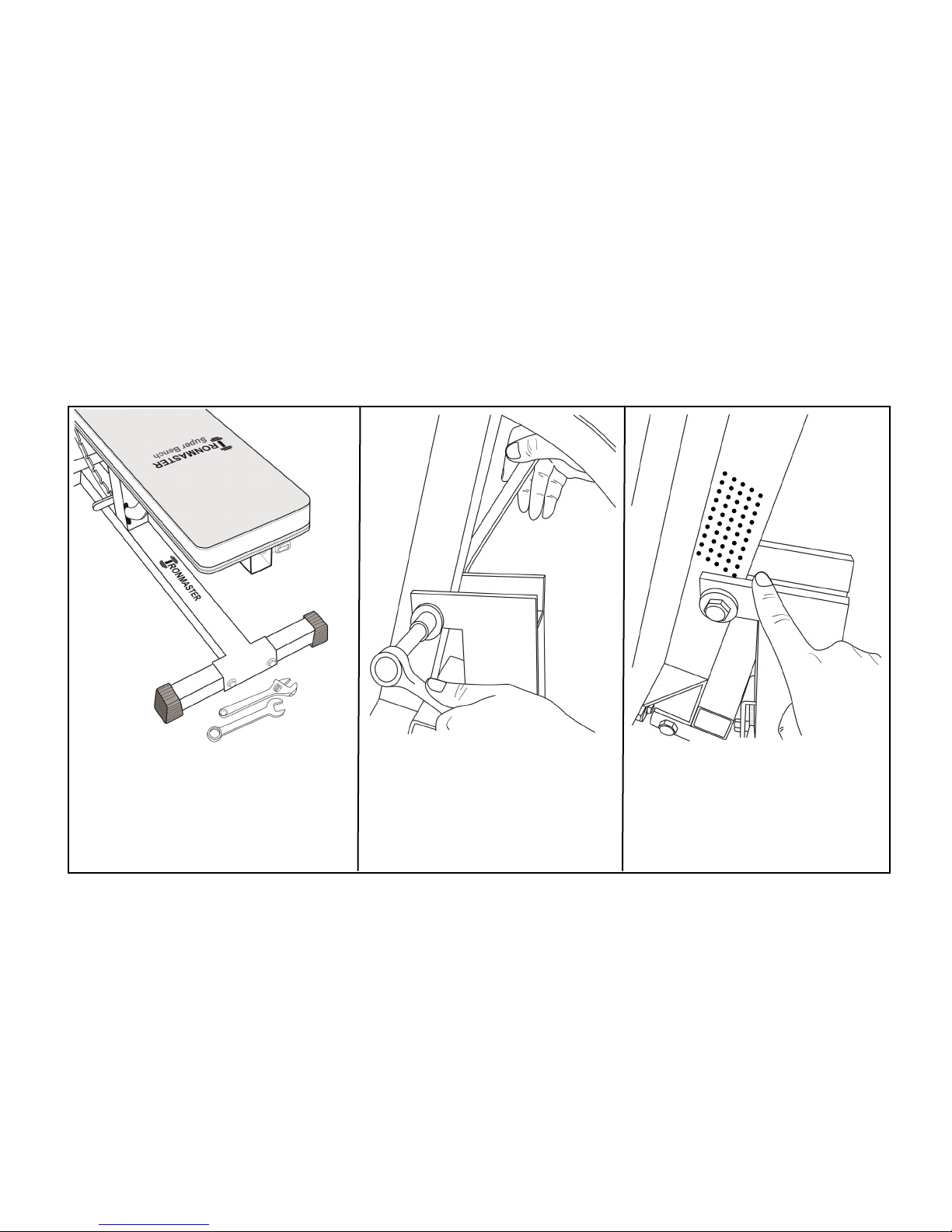
Check foot bolts regularly and tighten
as needed. Only use the Ironmaster
Step bench on a level non skid surface.
Failure to tighten bolts adequately will
result in a wobbly bench.
Maintenance and Troubleshooting:
The Super Bench is of very robust construction and will provide many years of trouble-free operation. For best
performance, please follow these simple steps for maintenance and increased product longevity.
1. Make sure to check and tighten (if needed) the four foot bolts on a regular basis. If bolts are discovered to be
loose, do not use the bench until bolts are retightened to approx 40 ft lbs.
2. The main pivot bolt needs to be checked on occasion. If this bolt loosens over time, the bench will not feel as sol-
id. You will require 2x 19mm wrenches to tighten this bolt. However, use care, if over-tightened the bench will not
function properly as the seat deck frame will be unable to rotate freely to sit into the lower frame and therefore it
will be difficult to bring the bench back to a full prone position.
3. The portion of the frame where the seat frame and lower frame meet is pre-lubricated from the factory with a gen-
erous amount of grease. Over time, this can become dirty/dried out and lead to premature rubbing/wear. If lubri-
cant is overly dirty or dried out, wipe the area clean with a dry cloth and re-lubricate the area with a light general
grease where the seat frame base and lower frame meet when the bench seat is down.
4. Periodically check tightness of the eight bolts holding the pad to the frame. Note it’s easiest to do this when the
bench is adjusted to a vertical position. Tighten if needed, but do not over-tighten as damage to the threaded
inserts on the deck may occur. Use the same procedure for the smaller incline seat pad.
The pivot bolt needs to be checked
periodically. If seat has a slight side
to side movement, tighten until
movement ceases. Do not over
tighten as it will impede movement.
Check for adequate lubrication
where the bottom of the seat frame
meets the lower frame as shown.
Use a light general grease in both
the pivot area and lever locking
mechanism (not pictured)
Warranty Information:
Ironmaster warrants to the original purchaser that this Home Fitness Product will be free from defects in workmanship and materials for a specific peri-
od from date of purchase based on the part type listed below. During the warranty period, Ironmaster will either repair or replace, at its option, defec-
tive part(s) at no charge. Warranty covers in home use only.
1 year for normal wear items such as rubber, upholstered parts and surface finishes.
10 years for frame and structural components.
Shipping costs are not included in the warranty and some items may need to be sent to Ironmaster for repair or replacement. Installation of any parts
and labor involved is not included. The warranties described above shall be the sole and exclusive remedy available to the purchaser. Correction of
defects, in the manner and for the period of time described above, shall constitute complete fulfillment of all liabilities and responsibilities of Ironmaster
to the purchaser with respect to the product, and shall constitute full satisfaction of all claims, whether based on contract, negligence, strict liability or
otherwise. In no event shall Ironmaster be liable or in any other way responsible for damages or defects in the product which were caused by repairs
or attempted repairs performed by anyone other than Ironmaster or Authorized service Contractor. This warranty shall not apply if the defect was
caused by misuse, neglect or normal wear and tear of the product purchased. Nor shall Ironmaster be liable or in any way responsible for any inci-
dental or consequential economic or property damage. Some states do not allow the exclusion of incidental or consequential damage, so the above
exclusion may not apply to you.
For customer service, contact your local distributor or:
Ironmaster LLC,14562 167th Ave SE Monroe, WA 98272 USA
Web site: www.ironmaster.com Email: support@ironmaster.com Tel: 800-533-3339 or 1-360-217-7780
Table of contents
Other Ironmaster Home Gym manuals


