manuals.online logo
Brands
  1. Home
  2. •
  3. Brands
  4. •
  5. IRROMETER
  6. •
  7. Gateway
  8. •
  9. IRROMETER WATERMARK 900M-CG/BP-LTE User manual

IRROMETER WATERMARK 900M-CG/BP-LTE User manual

Cellular Gateway – 900M-CG/BP-LTE
1
4
(6/18) #748
LITHO U.S.A.
Optimizing Irrigation . . . Maximizing Conservation . . .
Worldwide Since 1951
WARRANTY: The IRROMETER COMPANY warrants its products against defective
workmanship or materials under normal use for one year from date of purchase. Defective
parts will be replaced at no charge for either labor or parts if returned to the manufacturer
during the warranty period. The seller’s or manufacturer’s only obligation shall be to
replace the defective part and neither seller nor manufacturer shall be liable for any injury,
loss or damage, direct or consequential, arising out of the use of or inability to use the
product. This warranty does not protect against abuse, shipping damage, neglect,
tampering or vandalism, freezing or other damage whether intentionally or inadvertently
caused by the user.
®
1425 Palmyrita Ave., Riverside, CA 92507
951-682-9505 • FAX 951-682-9501
techsupport@irrometer.com
www.IRROMETER.com
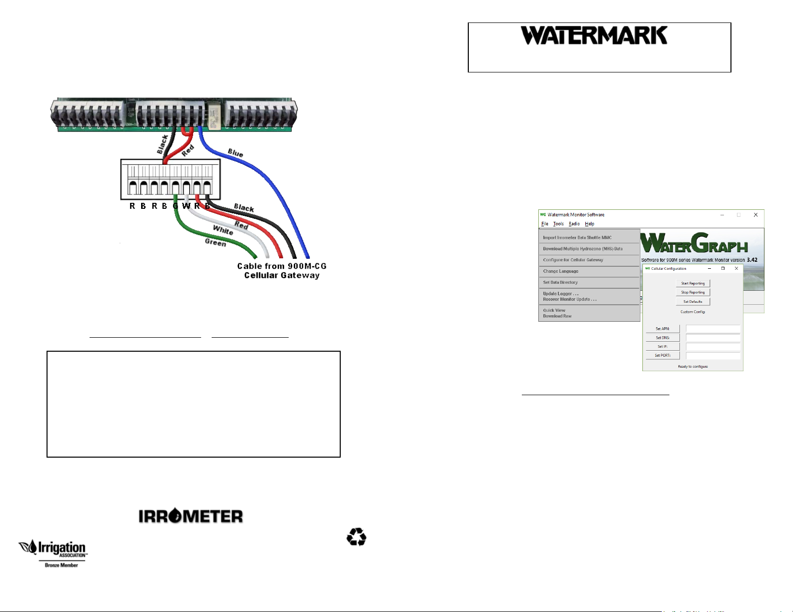
Terminal Strip inside of WATERMARK Monitor enclosure
If your 900M-CG/BP-LTE was ordered at the same time as a 900M WATERMARK
Monitor, both components will come from the factory with the latest firmware
version and be configured to use together.
INSTALL GUIDE
Configure the 900M for a Cellular Gateway
1. Select Tools then
Configure for
Cellular Gateway
2.
Username and Password can be changed after logging in by going to "User
Settings Page". To change the password, select "Change Password" and enter the
new password.
To create new users or modify existing users, select "Manage Users".
Data will be automatically collected and displayed once the system is installed and
operational. To power up the system, connect the red and black wires from the
solar panel to the loose yellow and black wires in the Cellular Gateway enclosure.
Connect the positive battery terminal to the battery to complete power up. The
system will begin reporting data within one hour.
For support and questions contact IRROMETER Co. at:
951-682-9505
[email protected] www.irrometer.com
IRROMETER Web Portal Access
Access to the Web Data Portal is at: http://portal.irrometer.com
Login with:
Username: ________________________
Password: ________________________
If adding a 900M-CG/BP-LTE to an existing 900M, the monitor must have a serial
number of 20000 or greater with a minimum firmware version of 2.9. It will also
need to be configured to work with the Cellular Gateway through WaterGraph
software. See the contact information for IRROMETER Co. on page 4 if a firmware
upgrade is required and follow the instructions below to configure the monitor to
work with the Cellular Gateway.
Click on Set Defaults in the Cellular Configuration
screen
3. Select Start Reporting to begin reporting.
32
Solar Panel Installation –
Attach the spade terminal ends of the wires to the appropriate battery terminals:
BLACK to the negative (–) terminal first, and then RED to the positive (+)
terminal. Batteries are shipped with the negative lead disconnected and taped
over.
DO NOT short the battery wire leads.
Shorting can cause fire. If the wires
become
shorted, place battery on a nonflammable surface outdoors for
observation for
15 - 20 minutes (battery can ignite even after 10 minutes).
To be sure exposed wires do not touch, make wire connections one at a time,
connecting the negative (BLACK) first. If you need to adjust the length of wires, cut
them separately. Do not allow exposed ends of wires to touch.
Make all terminal strip connections for power supply inside Monitor case
before attaching the RED (+) lead to the battery spade terminal.
A charge controller has been included to prevent overcharging batteries. Separate
charge controller instructions are included, should they be needed for
troubleshooting.
For 900M-CG/BP gateways connected directly to a WATERMARK Monitor:
1. Mount the 900M-CG/BP enclosure to the installed mast using the supplied clamps.
Maintain at least 3 ft. (1 m) between the 900M-CG enclosure and any other radio
device. Failure to maintain this distance may result in damage to the devices.
2. Route the 5 conductor cable from the 900M-CG/BP to the 900M and feed it
through the strain relief at the bottom of the Monitor enclosure.
3. Connect the 5 exposed wires to the terminal strip inside of the 900M per the
diagram on page 4.
4. Route 2 conductor power cable from the Solar Panel through the strain relief at the
bottom of the Cellular Gateway enclosure for connection to the Yellow and Black
wires of the battery. Attach the BLACK wire to the BLACK wire and the RED wire
to the YELLOW wire.
Angle the solar panel for maximum sun exposure, above the Cellular Gateway,
typically facing southwest (in the northern hemisphere) .
Fasten to mounting pole with band clamps.
5.
Maintenance –
The battery is sealed and requires no maintenance, but should be checked
annually for adequate voltage output.
The solar panel requires routine cleaning to provide adequate charging capacity. Even
a light coating of dust can significantly reduce its ability to maintain the battery charge.
It should be rinsed with clean water monthly and cleaned with window cleaner
seasonally.

Popular Gateway manuals by other brands

Lenze x510 Mounting and switch-on instructions

Lenze

Lenze x510 Mounting and switch-on instructions

Crestron infiNET EX CEN-GWEXER quick start

Crestron

Crestron infiNET EX CEN-GWEXER quick start

Bosch FCT-11M Specifications

Bosch

Bosch FCT-11M Specifications

Alphatech BlueGate SIP Quick installation guide

Alphatech

Alphatech BlueGate SIP Quick installation guide

CheckVideo CV4IP16 manual

CheckVideo

CheckVideo CV4IP16 manual

DBL Technology GoIP user manual

DBL Technology

DBL Technology GoIP user manual

Merak MMk-736 installation manual

Merak

Merak MMk-736 installation manual

Banner Sure Cross P2-KR manual

Banner

Banner Sure Cross P2-KR manual

ICP DAS USA DNP-211 quick start

ICP DAS USA

ICP DAS USA DNP-211 quick start

Dynamix DW FXS-08 user manual

Dynamix

Dynamix DW FXS-08 user manual

Technicolor DWA0120 Setup and user guide

Technicolor

Technicolor DWA0120 Setup and user guide

Westell Interchange iQ 2000 user guide

Westell

Westell Interchange iQ 2000 user guide

ribbon G5 Line Access Gateway R4.7 Interoperability guide

ribbon

ribbon G5 Line Access Gateway R4.7 Interoperability guide

ZyXEL Communications ADSL2+ 4-port Gateway P-660H-D Series quick start guide

ZyXEL Communications

ZyXEL Communications ADSL2+ 4-port Gateway P-660H-D Series quick start guide

Avaya RAD IPmux-14 TDMoIP Application notes

Avaya

Avaya RAD IPmux-14 TDMoIP Application notes

National Instruments NI WSN C Series Getting started guide

National Instruments

National Instruments NI WSN C Series Getting started guide

Winmate EAC Mini EACIL20 user manual

Winmate

Winmate EAC Mini EACIL20 user manual

Multitech E1 user guide

Multitech

Multitech E1 user guide

manuals.online logo
manuals.online logoBrands
  • About & Mission
  • Contact us
  • Privacy Policy
  • Terms and Conditions

Copyright 2025 Manuals.Online. All Rights Reserved.