IRT AAC-3390 User manual

AAC-3390
I.R.
T.
Communications
Pty
L
t
d
|
www
.i
rtcommunication
s.
c
o
m
Revision 04
Analogue Stereo to AES Audio Converter
User Manual

AAC-3390
I.R.
T.
Communications
Pty
L
t
d
|
www
.i
rtcommunication
s.
c
o
m
Page of 11
Revision 04
ANALOGUE STEREO TO AES AUDIO CONVERTER
Revision His ory:
Revision Da e By Change Descrip ion Applicable o:
01 01/0 / 001 AL IRT border page added for PDF format. S/N ≥ 9911001
0 01/0 /001 AL 00COMMON.doc file contents added. S/N ≥ 9911001
03 5/07/ 00 SAH Links updated. S/N ≥ 9911001
04 30/03/ 016 AL Circuit description removed.
Upgraded to I.R.T. Communications company name.
S/N ≥ 9911001

AAC-3390
I.R.
T.
Communications
Pty
L
t
d
|
www
.i
rtcommunication
s.
c
o
m
Page 3 of 11
Revision 04
USER MANUAL
Table of Con en s:
Sec ion Page
Revision History
Operational Safety 4
General Description 5
Technical Specifications 6
Configuration 7
Link settings 7
Potentiometer settings 7
Installation 8
Signal Connections 8
Selection of Internal or External Clock Reference 9
Front and rear layouts 10
Maintenance & Storage 11
Warranty & Service 11
This instruction book applies to units with serial number ≥ 9911001.

AAC-3390
I.R.
T.
Communications
Pty
L
t
d
|
www
.i
rtcommunication
s.
c
o
m
Page 4 of 11
Revision 04
OPERATIONAL SAFETY
WARNING
Operation of electronic equipment involves the use of voltages and currents that
may be dangerous to human life. Note that under certain conditions dangerous
potentials may exist in some circuits when power controls are in the OFF position.
Maintenance personnel should observe all safety regulations.
Do not make any adjustments inside equipment with power ON unless proper
precautions are observed. All internal adjustments should only be made by suitably
qualified personnel. All operational adjustments are available externally without
the need for removing covers or use of extender cards.

AAC-3390
I.R.
T.
Communications
Pty
L
t
d
|
www
.i
rtcommunication
s.
c
o
m
Page 5 of 11
Revision 04
GENERAL DESCRIPTION
The IRT AAC-3390 is an analogue audio to AES/EBU digital audio signal converter, and converts standard stereo
analogue audio signals to the AES3-199 and SMPTE- 76 AES digital audio standard.
The input signals are a stereo pair of balanced audio at the standard +4 dBu line up level.
The outputs are three serial digital audio signals; one unbalanced BNC connection on the front panel for
monitoring and two from the rear panel assembly. The latter can be 110 Ohms balanced using the ZAC-3391 rear
panel assembly or 75 Ohms unbalanced BNC connections using the ZAC-3390 rear panel assembly.
A further input is provided for a reference AES input signal to lock the signal from the AAC-3390 to a station
reference.
The reference input can be either 110 Ohms terminating balanced line or 75 Ohms terminating unbalanced line.
Both connections are provided on the rear panel assembly. Selection of the input type is by links on the AAC-3390
main circuit board.
Front panel LED indicators are provided for DC voltage, presence of input audio levels above -30 dBu, lock to
external AES reference and overflow at 0 dBFS corresponding to the + 4 dBu full scale input audio level.
The AAC-3390 is designed to fit the IRT range of Eurocard mounting frames, including the 1 or 10 slot 3 RU and
slot 1 RU rack mounting frames.
S andard fea ures:
•
Balanced s ereo inpu s.
•
High impedance or 600 Ohm inpu ermina ion
.
•
AES ex ernal reference inpu
.
•
Balanced 110 Ω or unbalanced 75 Ω AES ou pu rear assembly op ions.
•
Fron panel AES moni oring poin
.
BLOCK DIAGRAM AAC-3390 SIGNAL PATH
A to D
converter Gen-lock
AES reference
input
L input
R input AES outputs
Overflow Ext. ref.
In use
L
R
Mon. output
Int. / Ext.
Select

AAC-3390
I.R.
T.
Communications
Pty
L
t
d
|
www
.i
rtcommunication
s.
c
o
m
Page 6 of 11
Revision 04
TECHNICAL SPECIFICATIONS
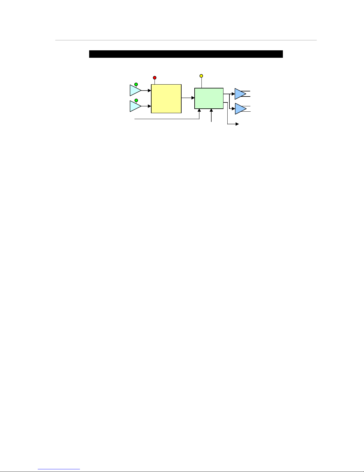
Inpu s:
Analogue inpu s:
Number channels – one stereo pair.
Type > 30 kΩ balanced analogue audio.
Inpu coupling AC
Inpu level se ing + 4 dBu for 0 dBFS digital signal.
Inpu connec or Removable screw terminal block and Krone LSE IDC in parallel.
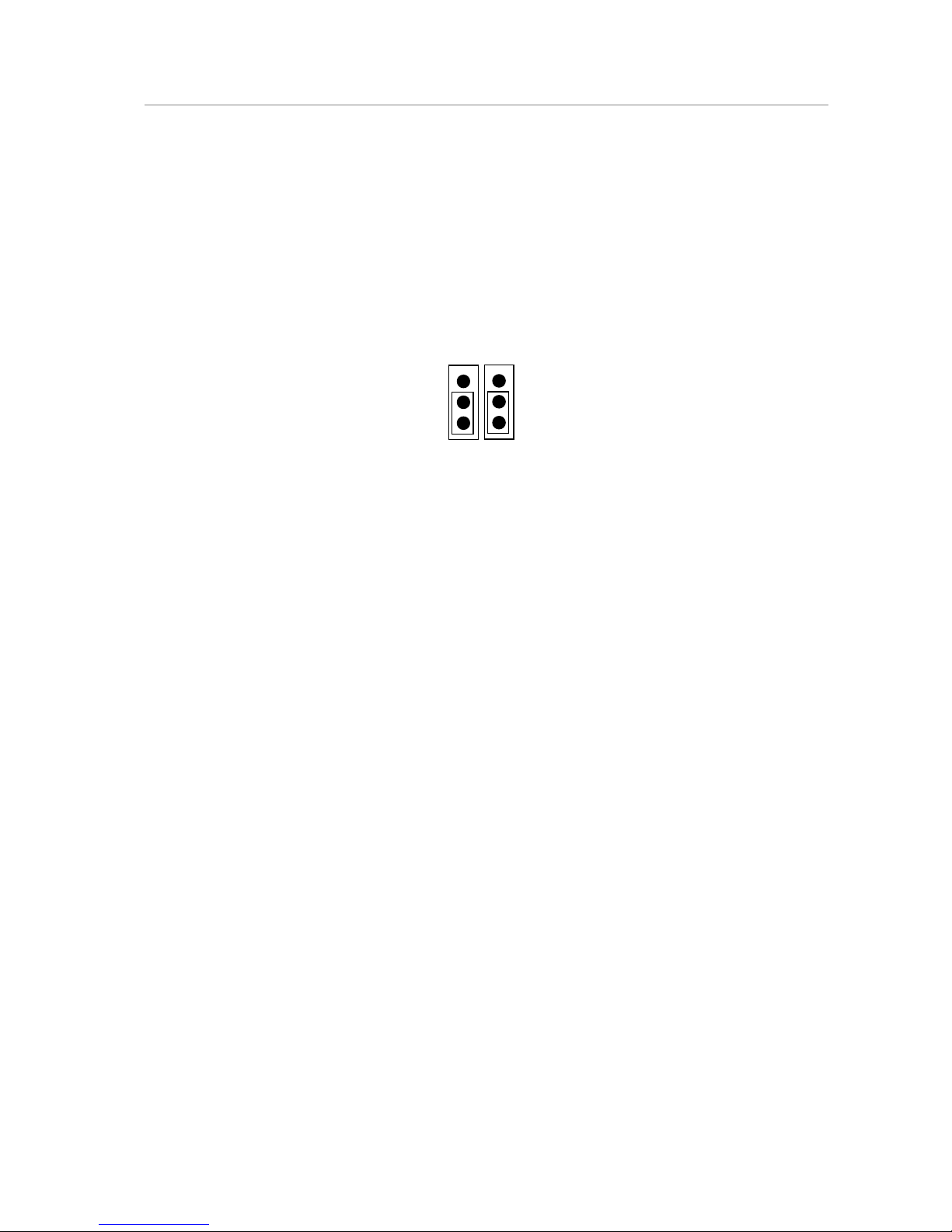
Reference inpu :
Type 1 x 110 Ω balanced terminating;
and
1 x 75 Ω unbalanced terminating.
Selected by links on module PCB.
Forma AES3-199 standard.
Inpu level 00 mVp-p minimum.
Inpu cable leng h > 500 m Belden (8 81).
> 00 m 110 Ω (AES digital high quality shielded pair).
Ou pu s:
AES/EBU:
Rear panel ype ZAC-3390 x 75 Ω unbalanced >1 Vp-p.
or
Rear panel ype ZAC-3391 x 110 Ω balanced >3 Vp-p.
Fron panel moni oring 1 x 75 Ω unbalanced >1 Vp-p.
Forma AES3-199 standard.
Performance:
Sample ra e 48 kHz internal rate, or as set by external reference.
Ou pu signal rise and fall imes < 0 ns.
Frequency response +/-0.05 dB 0 Hz to 0 kHz.
THD + N -95 dB, 0 Hz – 0 kHz @ -4 dBFS.
In er-channel cross alk -100 dB ( 0 Hz – 0 kHz).
Lineari y +/-0.5 dB at –90 dBFS.
Power Requiremen s:
Vol age 8 Vac CT (14-0-14) or ±16 Vdc
Power consump ion 3.5 VA.
Connec ors:
Unbalanced BNC.
Balanced Removable screw terminal blocks.
O her:
Tempera ure range 0 - 50° C ambient.
Mechanical Suitable for mounting in IRT 19" rack chassis with input, output and power
connections on the rear panel.
Finish: Fron panel Grey background, black lettering & red IRT logo.
Rear assembly Detachable silk-screened PCB with direct mount connectors to Eurocard and
external signals.
Dimensions 6 HP x 3 U x 0 mm IRT Eurocard.
Due to our policy of continuing development, these specifications are subject to change without notice.

AAC-3390
I.R.
T.
Communications
Pty
L
t
d
|
www
.i
rtcommunication
s.
c
o
m
Page 7 of 11
Revision 04
CONFIGURATION
Link se ings:
NOTE: Links LK6 and LK15 must both be set to the same setting, that is both OUT or both IN.
LK6 + LK15 OUT Lock AES output to external AES reference (if present).
IN Lock AES output to internal 48 kHz clock reference.
NOTE: Links SW1 and SW must both be set to the same setting, that is both 75 or both 110.
SW1 + SW2 75 AES reference input 75 Ohm unbalanced BNC.
110 AES reference input 110 Ohm balanced 3-pin Phoenix plug type.
Rear Assembly:
Rear assembly links LK1 and LK open circuit (default) = analogue input impedance > 30 kΩ.
Rear assembly links LK1 and LK short circuited = analogue input impedance 600 Ω.
To short circuit rear assembly links LK1 and LK , solder a wire link in place.
Po en iome er se ings:
RV1 and RV set the AES output level. This is factory set at 4dBFS with an analogue input level of + 0dBu.
RV3 sets when the analogue audio LEDs illuminate and has been factory set for a -30 dBu analogue input signal.
75 110
SW1 SW

AAC-3390
I.R.
T.
Communications
Pty
L
t
d
|
www
.i
rtcommunication
s.
c
o
m
Page 8 of 11
Revision 04
INSTALLATION
Pre-ins alla ion:
Handling:
This equipment may contain or be connected to static sensitive devices and proper static free handling precautions
should be observed.
Where individual circuit cards are stored, they should be placed in antistatic bags. Proper antistatic procedures
should be followed when inserting or removing cards from these bags.
Power:
AC mains supply: Ensure that operating voltage of unit and local supply voltage match and that correct rating
fuse is installed for local supply.
DC supply: Ensure that the correct polarity is observed and that DC supply voltage is maintained within
the operating range specified.
Ear hing:
The earth path is dependent on the type of frame selected. In every case particular care should be taken to ensure
that the frame is connected to earth for safety reasons. See frame manual for details.
Signal ear h: For safety reasons a connection is made between signal earth and chassis earth.
No attempt should be made to break this connection.
Ins alla ion in frame or chassis:
See details in separate manual for selected frame type.
Signal Connec ions:
Input signal connections are made to the two removable screw terminal blocks at SK1 and SK .
The audio inputs are bridging > 30 kΩ, if a 600 Ω termination is required close LK1 and LK with a wire link soldered
at the LK1 and LK positions on the rear panel.
Output signal connections are made to connectors SK3 and SK4 on the selected rear panel of the AAC-3390.
Use rear panel ZAC-3390 for two unbalanced 75 ohms BNC output circuits or rear panel ZAC-3391 for two balanced
100 ohms output circuits.
The reference input signal can be either at SK5 a 75 ohms unbalanced terminating input or at SK6 a 110 ohms
balanced terminating input, the inpu selec ion is done by links SW1, SW2 on he module pcb near pin 3 of the
board connector. Move the links provided to the 75 or 110 positions marked on the board as required. The
reference input signal will then be connected to the appropriate input connector on the rear panel.
The presence of AES signal at the output of the ZAC-3390 can be monitored using the front panel monitoring BNC
socket provided.

AAC-3390
I.R.
T.
Communications
Pty
L
t
d
|
www
.i
rtcommunication
s.
c
o
m
Page 9 of 11
Revision 04
Selec ion of In ernal or Ex ernal Clock Reference:
For fixed in ernal clock reference close links LK6 and LK15 on the module main circuit board.
For a clock reference selectable between the internal clock and the external clock open links LK6 and LK15 on the
module main circuit board. In this mode of operation the AAC-3390 will lock to a external reference applied to the
external reference input selected by SW1 and SW , whenever his reference is presen and rever o he in ernal
crys al clock reference if he ex ernal reference is removed.
NOTE: It is important for the operation of the AAC-3390 that links LK6 and LK15 by bo h open or closed oge her
never individually.

AAC-3390
I.R.
T.
Communications
Pty
L
t
d
|
www
.i
rtcommunication
s.
c
o
m
Page 10 of 11
Revision 04
Fron & rear panel connec or diagrams
:
ZAC-3390
Unbalanced AES O/P’s
Rear Assembly
(Option)
Analogue
Input:
Left
Right
Unbalanced
AES O/P’s
Reference
AES I/P
(Bal/Unbal
Link select)
ZAC-3391
Balanced AES O/P’s
Rear Assembly
(Standard)
Analogue
Input:
Left
Right
Balanced
AES O/P’s
Reference
AES I/P
(Bal/Unbal
Link select)

AAC-3390
I.R.
T.
Communications
Pty
L
t
d
|
www
.i
rtcommunication
s.
c
o
m
Page 11 of 11
Revision 04
MAINTENANCE & STORAGE
Main enance:
No regular maintenance is required.
Care however should be taken to ensure that all connectors are kept clean and free from contamination of any
kind. This is especially important in fibre optic equipment where cleanliness of optical connections is critical to
performance.
S orage:
If the equipment is not to be used for an extended period, it is recommended the whole unit be placed in a sealed
plastic bag to prevent dust contamination. In areas of high humidity a suitably sized bag of silica gel should be
included to deter corrosion.
Where individual circuit cards are stored, they should be placed in antistatic bags. Proper antistatic procedures
should be followed when inserting or removing cards from these bags.
WARRANTY & SERVICE
Equipment is covered by a limited warranty period of three years from date of first delivery unless contrary
conditions apply under a particular contract of supply. For situations when “No Faul Found” for repairs, a
minimum charge of 1 hour’s labour, at IRT’s current labour charge rate, will apply, whether the equipment is
within the warranty period or not.
Equipment warranty is limited to faults attributable to defects in original design or manufacture. Warranty on
components shall be extended by IRT only to the extent obtainable from the component supplier.
Equipmen re urn:
Before arranging service, ensure that the fault is in the unit to be serviced and not in associated equipment. If
possible, confirm this by substitution.
Before returning equipment contact should be made with IRT or your local agent to determine whether the
equipment can be serviced in the field or should be returned for repair.
The equipment should be properly packed for return observing antistatic procedures.
The following information should accompany the unit to be returned:
1. A fault report should be included indicating the nature of the fault
. The operating conditions under which the fault initially occurred.
3. Any additional information, which may be of assistance in fault location and remedy.
4. A contact name and telephone and fax numbers.
5. Details of payment method for items not covered by warranty.
6. Full return address.
7. For situations when “No Faul Found” for repairs, a minimum charge of 1 hour’s labour will apply,
whether the equipment is within the warranty period or not. Contact IRT for current hourly rate.
Please note that all freight charges are the responsibility of the customer.
The equipment should be returned o he agen who originally supplied he equipmen or, where this is not
possible, to IRT directly. Details of IRT’s direct address can be found at I.R.T. Communications’ website.
Web address: www.irtcommunications.com
Email: [email protected]
Table of contents
Popular Media Converter manuals by other brands

AJA
AJA HELO Installation and operation guide

Link electronics
Link electronics DigiFlex 1166 Specification sheet

Siemens
Siemens SINAMICS G120XA operating instructions

HP
HP E1418A Service manual

Moxa Technologies
Moxa Technologies TCF-142-S user manual

Colorado Data Systems
Colorado Data Systems 53A-571 operating manual