IRT DDS-1100 User manual

1100-dds_ib_rev0.doc Page 1 of 9 06/10/2009
IRT 1RU
Type DDS-1100
G.703 8x4 Switcher
Designed and manufactured in Australia
IRT can be found on the Internet at:
http://www.irtelectronics.com
I R T Electronics Pty Ltd A.B.N. 35 000 832 575
26 Hotham Parade, ARTARMON N.S.W. 2064 AUSTRALIA
National: Phone: (02) 9439 3744 Fax: (02) 9439 7439
International: +61 2 9439 3744 +61 2 9439 7439
Email: sales@irtelectronics.com
Web: www.irtelectronics.com

1100-dds_ib_rev0.doc Page 2 of 9 06/10/2009
IRT 1RU
Type DDS-1100
G.703 8x4 Switcher
Instruction Book
Table of Contents
Section Page
Operational Safety 2
General Description 3
Technical Specifications 4
Installation 5
Front and rear layouts 5
Operation 6
Front panel control 6
Serial control 7
Maintenance & Storage 8
Warranty & Service 8
Equipment return 8
Drawing List Index 9
This instruction book applies to units later than S/N 0206001.
Operational Safety:
WARNING
Operation of electronic equipment involves the use of voltages and currents that
may be dangerous to human life. Note that under certain conditions dangerous
potentials may exist in some circuits when power controls are in the OFF position.
Maintenance personnel should observe all safety regulations.
Do not make any adjustments inside equipment with power ON unless proper
precautions are observed. All internal adjustments should only be made by suitably
qualified personnel. All operational adjustments are available externally without the
need for removing covers or use of extender cards.

1100-dds_ib_rev0.doc Page 3 of 9 06/10/2009
IRT Eurocard
Type DDS-1100
G.703 8x4 Switcher
General Description
The DDS-1100 is a broadband 8x4 switcher for use with 2, 8, 34 & 45 Mb/s G.703 compliant signals.
Any of the 8 inputs can be switched to any or all of the 4 outputs.
The switcher is capable of being controlled locally, using front panel switches, or remotely, via an RS485 interface.
The switcher is mounted in a 1 RU case and may be powered by a multi voltage AC mains input.
All inputs and outputs are via 75ΩBNC connectors mounted on the rear of the chassis.
Standard features:
•Routing switcher for use with such signals as 2, 8, 34 or 45 Mb/s G.703 signals
•8 inputs
•4 outputs.
•Local or remote control.

1100-dds_ib_rev0.doc Page 4 of 9 06/10/2009
Technical Specifications
Type DDS-1100
Inputs:
Input signal Broadband signals such as 2/8/34/45 Mb/s compliant to G.703
Number 8.
Type AC coupled
Impedance 75 Ωterminated
Return loss Better than –15 dB @ 100 MHz.
Output:
Output signal As per input
Number 4
Type DC coupled
Impedance Nominal 75 Ωsource
Performance:
(8 x 2 configuration.)
Frequency response >200 MHz (-3 dB point)
(any input to any output)
Group delay 3 ns to 200 MHz
Gain input – output ±1 dB @ 100 MHz
Intrinsic jitter <0.05 UIp-p
Logic interface: RS485 Baud Rates: 38900
19200
9600
4800
Indicators:
Front Panel 1) Power on.
(LED) 2) Switch tally.
Power requirements 110/130/220/240 Vac ±10%.
Power consumption <10 VA.
Connectors: Signal BNC.
Remote 9 pin 'D' female.
Power AC IEC 320.
Other:
Temperature range 0 - 50° C ambient.
Mechanical IRT 19" rack chassis with input, remote interface, output and power
connections on the rear panel.
Finish: Front panel Grey, black lettering & red IRT logo.
Rear panel Silk-screened bright passivated steel, silk-screened black lettering.
Dimensions 44 mm x 480 mm x 230 mm.
Due to our policy of continuing development, these specifications are subject to change without notice.

1100-dds_ib_rev0.doc Page 5 of 9 06/10/2009
Installation
Pre-installation:
Handling:
This equipment may contain or be connected to static sensitive devices and proper static free handling precautions
should be observed.
Where individual circuit cards are stored, they should be placed in antistatic bags. Proper antistatic procedures
should be followed when inserting or removing cards from these bags.
Power:
AC mains supply: Ensure that operating voltage of unit and local supply voltage match and that correct rating
fuse is installed for local supply.
Earthing:
The earth path is dependent on the type of frame selected. In every case particular care should be taken to ensure
that the frame is connected to earth for safety reasons. See frame manual for details.
Signal earth: For safety reasons a connection is made between signal earth and chassis earth. No attempt should be
made to break this connection.
Signal Connections:
G.703 Inputs:
Eight (8) inputs marked 1 to 8 are 75 Ohm BNC type for connection to broadband signals, such as 2/8/34/45 Mb/s
compliant to G.703, using quality 75 Ohm coaxial cable. Inputs on rear assembly correspond to the eight
pushbuttons on the front panel marked INPUTS 1 to 8.
G.703 Outputs:
Four (4) outputs marked A, B, C, D are 75 Ohm BNC type for connection to broadband equipment, requiring
2/8/34/45 Mb/s compliant to G.703, using quality 75 Ohm coaxial cable. Outputs on rear assembly correspond to
the four pushbuttons on the front panel marked OUTPUTS A, B, C & D.
Front & rear panel connector diagrams
The following front panel and rear assembly drawings are not to scale and are intended to show connection order
and approximate layout only.
DDS-1100 8x4 G.703 SWITCHER
OUTPUTS
C
A
DB
3
1
42
7
5
86
INPUTS
SERIAL
CONTROL
A
B C D 1 2 3 4 5 6 7 8

1100-dds_ib_rev0.doc Page 6 of 9 06/10/2009
Operation
Front panel control:
Press desired OUTPUT A, B, C or D, then press which input that is to be switched to that output.
For example, suppose the requirement was for input 1 to go to outputs C and D, input 2 was to go to output B and
input 8 was to go to output A.
In any order, momentarily press:
OUTPUT A followed by INPUT 8;
OUTPUT B followed by INPUT 2;
OUTPUT C followed by INPUT 1; and
OUTPUT D followed by INPUT 1.
The front panel switches have a red LED which illuminates when the pushbutton is pressed. Pressing any of the
OUTPUT switches will show what INPUT switch has already been set to match. To reset simply press another
desired INPUT.

1100-dds_ib_rev0.doc Page 7 of 9 06/10/2009
Serial control:
Baud rate is 9600, 8 bits of data in each byte, no parity
SELECT CROSSPOINT
1 BREAK
2 ADDRESS Must match setting of Address SW
3 WORD COUNT 3
4 COMMAND $80 Row 1
$81 Row 2
$82 Row 3
$83 Row 4
5 VALUE 0 to 7
6 CHECK SUM 8 bit sum of bytes 2 to 5 inclusive.
REPORT CROSSPOINT
1 BREAK
2 ADDRESS Must match setting of Address SW
3 WORD COUNT 2
4 COMMAND $40 Row 1
$41 Row 2
$42 Row 3
$43 Row 4
5 CHECK SUM 8 bit sum of bytes 2 to 4 inclusive.
DB9 pin numbering:
1. Gnd chassis
2. FD-
3. HD+
4. Gnd signal
5. N/C
6. Gnd signal
7. FD+
8. HD-
9. Gnd chassis
D9F
2
7
4
8
3
6
D9F
2
7
4
8
3
6
Remote control
5 4 3 2 1
9 8 7 6
9 pin female ‘D’ connector
as viewed at chassis rear

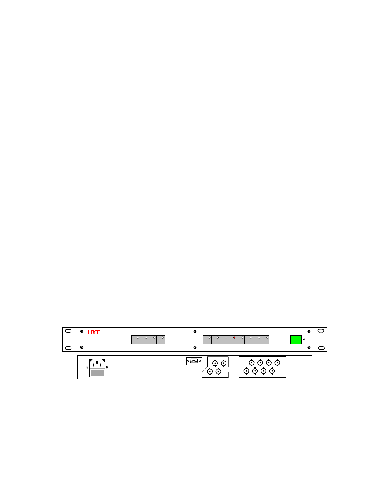
1100-dds_ib_rev0.doc Page 8 of 9 06/10/2009
Maintenance & Storage
Maintenance:
No regular maintenance is required.
Care however should be taken to ensure that all connectors are kept clean and free from contamination of any kind.
This is especially important in fibre optic equipment where cleanliness of optical connections is critical to
performance.
Storage:
If the equipment is not to be used for an extended period, it is recommended the whole unit be placed in a sealed
plastic bag to prevent dust contamination. In areas of high humidity a suitably sized bag of silica gel should be
included to deter corrosion.
Where individual circuit cards are stored, they should be placed in antistatic bags. Proper antistatic procedures
should be followed when inserting or removing cards from these bags.
Warranty & Service
Equipment is covered by a limited warranty period of one year from date of first delivery unless contrary conditions
apply under a particular contract of supply. For situations when “No Fault Found” for repairs, a minimum charge
of 1 hour’s labour, at IRT’s current labour charge rate, will apply, whether the equipment is within the warranty
period or not.
Equipment warranty is limited to faults attributable to defects in original design or manufacture. Warranty on
components shall be extended by IRT only to the extent obtainable from the component supplier.
Equipment return:
Before arranging service, ensure that the fault is in the unit to be serviced and not in associated equipment. If
possible, confirm this by substitution.
Before returning equipment contact should be made with IRT or your local agent to determine whether the
equipment can be serviced in the field or should be returned for repair.
The equipment should be properly packed for return observing antistatic procedures.
The following information should accompany the unit to be returned:
1. A fault report should be included indicating the nature of the fault
2. The operating conditions under which the fault initially occurred.
3. Any additional information, which may be of assistance in fault location and remedy.
4. A contact name and telephone and fax numbers.
5. Details of payment method for items not covered by warranty.
6. Full return address.
7. For situations when “No Fault Found” for repairs, a minimum charge of 1 hour’s labour will apply,
whether the equipment is within the warranty period or not. Contact IRT for current hourly rate.
Please note that all freight charges are the responsibility of the customer.
The equipment should be returned to the agent who originally supplied the equipment or, where this is not
possible, to IRT direct as follows.
Equipment Service
IRT Electronics Pty Ltd
26 Hotham Parade
ARTARMON
N.S.W. 2064
AUSTRALIA
Phone: 61 2 9439 3744 Fax: 61 2 9439 7439

1100-dds_ib_rev0.doc Page 9 of 9 06/10/2009
Drawing List Index
Drawing # Sheet # Description
804106 1 DDS-1100 8x4 G.703 Switcher circuit diagram – sheet 1 of 4.
804106 2 DDS-1100 8x4 G.703 Switcher circuit diagram – sheet 2 of 4.
804106 3 DDS-1100 8x4 G.703 Switcher circuit diagram – sheet 3 of 4.
804106 4 DDS-1100 8x4 G.703 Switcher circuit diagram – sheet 4 of 4.

Title
SCALE
SIZE
Sheet
DRAWN
CHECKED
ENG. APP.
Revision:
DO NOT COPY NOR
DISCLOSE TO ANY
THIRD PARTY
WITHOUT WRITTEN
CONSENT
of1
IRT Electronics Pty. Ltd.
Drawing No.
COPYRIGHT
ARTARMON NSW AUSTRALIA 2064
A3
N.T.S. 4
DSS-1100
804106
Date: 6-Oct-2009
1 12-03-02
8x4 G.703 SWITCHER
R73
10M
XL1
3.6864Mhz
C50
10pF
C49
10pF
VOUT
1VBAT 8
PFI
4
GND
3
VCC
2
PFO 5
MR 6
RST 7
U6
MAX704
R74
100K
+VC +VC
+VC +VC
+VC
R88 560R
R87 560R
R86 560R
R85 560R
R78 560R
R82 560R
R81 560R
R80 560R
2 1
LD1
SERIAL
2 1
LD2
LD
R70
560R
R71
560R
+5V +5V
ROW D0 PL1/3A
ROW D1 PL1/2B
ROW D2 PL1/2A
ROW STROBE PL1/3B
O/P D0 PL2/3A
O/P D1 PL2/2B
O/P D2 PL2/2A
O/P STROBE PL2/3B
VS1-4 29
VS4 30
VS3 30
VS2 30
VS1 30
VS1-4 28
VS1-4 27
8
7
1
2
6
5
4
3
R
D
U7
MAX485
8
7
1
2
6
5
4
3
R
D
U8
MAX485
LK2
R75
4K7
+VC
+VC
+5V
R76
220R
R77
220R
LK3
LK4
P2/19ab
P2/18ab
P2/17ab
P2/16ab
C51,53,54,56,58
10uF
C52,55,57,59
100nF
+VC +VC
R72
4K7
LK1
+5V
RP3
4K7
SW1
+VC
ADDRESS
BAUD RATE
Name
804106S2.SCH
Name
804106S3.SCH
Name
804106S4.SCH
RESET
1IRQ
2
VPP
3
PA7 4
PA6 5
PA5 6
PA4 7
PA3 8
PA2 9
PA1 10
PA0 11
PB0 12
PB1 13
PB2 14
PB3 15
PB4 16
PB5 17
PC6
22 PC5
23 PC4
24 PC3
25 PC2
26 PC1
27 PC0
28
PD0/RDI
29
PD1/TDO
30
PD2/MISO
31
PD3/MOSI
32
PD4/SCK
33
PD5/SS
34
TCMP 35
PD7
36
VSS
20
VDD
40
PB7 19
PB6 18
PC7
21
OSC1 39
OSC2 38
TCAP 37
U5
MC68HC705C8
2
7
8
3
PC804189
X
X
X
X
X
X
X
X
I
O
I
MSB LSB
BAUD RATE
OO
O
I
I
38,900
19,200
9,600
4,800
RATE
O
O
I
O
O
I
I
I
MSB LSB
ADDRESS
OO
O
THROUGH TO
I
0
15
ADDRESS
1

Title
SCALE
SIZE
Sheet
DRAWN
CHECKED
ENG. APP.
Revision:
DO NOT COPY NOR
DISCLOSE TO ANY
THIRD PARTY
WITHOUT WRITTEN
CONSENT
of2
IRT Electronics Pty. Ltd.
Drawing No.
COPYRIGHT
ARTARMON NSW AUSTRALIA 2064
A3
N.T.S. 4
DSS-1100
804106
Date: 6-Oct-2009
T3
T2
T1
SW0
SW1
SW2
SW3
SW4
T0
+5
EPM7064SL44
40
+5
23 15 35 3
22 30 10 42
P2
PL101
U101
1A
1B
2A
2B
3A
3B
444
MINEIN
MINEOUT
STROBE
14
DI0
DI1
DI2
13
12
11
25
24
27
26
28
29
31
32
T4
T5
T6
T7
41
39
38
37
36
33
34
SW5
SW6
SW7
+5
+5
1
2
SW1
SW2
SW3
SW4
SW5
21
LD1
21
LD2
21
LD3
21
LD4
21
LD5
21
LD6
21
LD7
21
LD8
SW6
SW7
SW8
21 R109
560R
1 12-03-02
C101
10uF
+5V
8x4 G.703 SWITCHER
21 R102 10K
R103 10K
R104 10K
21 R105 10K
21 R106 10K
21 R107 10K
21 R108 10K
21 R101 10K
+5V
+5V
+5V
+5V
+5V
+5V
+5V
+5V

Title
SCALE
SIZE
Sheet
DRAWN
CHECKED
ENG. APP.
Revision:
DO NOT COPY NOR
DISCLOSE TO ANY
THIRD PARTY
WITHOUT WRITTEN
CONSENT
of3
IRT Electronics Pty. Ltd.
Drawing No.
COPYRIGHT
ARTARMON NSW AUSTRALIA 2064
A3
N.T.S. 4
DSS-1100
804106
Date: 6-Oct-2009
1 12-03-02
8x4 G.703 SWITCHER
VIN- 2
VIN+ 1
+V
5
-V
3
6
7
CONV1
PBBA-C
VIN- 2
VIN+ 1
+V
5
-V
3
6
7
CONV2
PBBA-C
-
+
D1-4 1 3
2
FIL1
DSS306
1 3
2
FIL2
DSS306
R95
1R
R96
1R
R83
4R7
R84
4R7
C82
470uF
C84
470uF
C86
470uF
C87
470uF
C85
470uF
C83
470uF
C81
100nF
C64
100nF
C79
100nF
C80
10uF
L4
10uH
R90
10R
1
2
4
5
6
D C
D C
CONV3
NMH05095
C77
100nF
C78
10uF
C76
10uF
C75
100nF
C69
100nF C71
100nF
C72
10uF
C74
10uF C73
100nF
C70
100nF
C67
100nF
C65
100nF
C68
10uF
C66
10uF
L3
10uH
L6
4.7uH
L5
4.7uH
3 1
2
LK20/21
31
2
LK22/23
C41
100nF
C43
10uF
L1
4.7uH
C37
10uF
C39
100nF
C45
100nF
C42
100nF
C44
10uF
L2
4.7uH
C38
10uF
C40
100nF
C46
100nF
+VB
-VB
+VD
+VC
3
2
1
AC IN
+VA
-VA
C48
10uF
C47
10uF
+9V
-9V

Title
SCALE
SIZE
Sheet
DRAWN
CHECKED
ENG. APP.
Revision:
DO NOT COPY NOR
DISCLOSE TO ANY
THIRD PARTY
WITHOUT WRITTEN
CONSENT
of4
IRT Electronics Pty. Ltd.
Drawing No.
COPYRIGHT
ARTARMON NSW AUSTRALIA 2064
A3
N.T.S. 4
DDS-1100
804106
Date:
1
6-Oct-2009
GND/32
/GL/31
/ST/30
C/29
B/28
A/27
Vcc/26
Vee/25
OUT/24
GND/23
GND/22
IP8/21
GND/20
IP7/19
GND/18
GND/17
IP6/16
GND/15
GND/14
IP5/13
GND/12
GND/11
IP4/10
GND/9
GND/8
IP3/7
GND/6
GND/5
IP2/4
GND/3
GND/2
IP1/1
GND/32
/GL/31
/ST/30
C/29
B/28
A/27
Vcc/26
Vee/25
OUT/24
GND/23
GND/22
IP8/21
GND/20
IP7/19
GND/18
GND/17
IP6/16
GND/15
GND/14
IP5/13
GND/12
GND/11
IP4/10
GND/9
GND/8
IP3/7
GND/6
GND/5
IP2/4
GND/3
GND/2
IP1/1
GND/32
/GL/31
/ST/30
C/29
B/28
A/27
Vcc/26
Vee/25
OUT/24
GND/23
GND/22
IP8/21
GND/20
IP7/19
GND/18
GND/17
IP6/16
GND/15
GND/14
IP5/13
GND/12
GND/11
IP4/10
GND/9
GND/8
IP3/7
GND/6
GND/5
IP2/4
GND/3
GND/2
IP1/1
GND/32
/GL/31
/ST/30
C/29
B/28
A/27
Vcc/26
Vee/25
OUT/24
GND/23
GND/22
IP8/21
GND/20
IP7/19
GND/18
GND/17
IP6/16
GND/15
GND/14
IP5/13
GND/12
GND/11
IP4/10
GND/9
GND/8
IP3/7
GND/6
GND/5
IP2/4
GND/3
GND/2
IP1/1
VS1 VS2 VS3 VS4
P1/5,AB
P1/8,AB
P1/29,AB
P1/26,AB
P1/22,AB
P1/19,AB
P1/15,AB
P1/12,AB
P1/27,28,30,31,AB
P1/23,24,25,AB
P1/20,21,AB
P1/16,17,18,AB
P1/13,14,AB
P1/9,10,11,AB
P1/6,7,AB
P1/2,3,4,AB
+Va
-Va
P2/9,AB
P2/8,AB
P2/6,AB
P2/4,AB
P2/10,AB
P2/2,AB
+Va
-Va
P2/7,AB
+Va
-Va
P2/5,AB
+Va
-Va
P2/3,AB
TP2 TP1
-VA
+VA
8x4 G.703 SWITCHER
+VB
-VB
U5/16 U5/15 U5/14 U5/13
U5/19
U5/18
U5/12
C7
1uF
C8
10nF
C1
1uF
C2
10nF
C3
1uF
C4
10nF
C5
1uF
C6
10nF
C9
1uF
C10
10nF
C11
1uF
C12
10nF
C13
1uF
C14
10nF
C15
1uF
C16
10nF
21 R46
143R
21 R40
143R
21 R34
143R
21 R28
143R
21 R22
143R
21 R16
143R
21 R10
143R
21 R4
143R
21 R5
143R
21 R11
143R
21 R17
143R
21 R23
143R
21 R29
143R
21 R35
143R
21 R41
143R
21 R47
143R
21 R48
143R
21 R42
143R
21 R36
143R
21 R30
143R
21 R24
143R
21 R18
143R
21 R12
143R
21 R6
143R
21 R51
75R
21 R52
240R
21 R53
75R
2 1
R44
39R
2 1
R45
143R
2 1
R38
39R
2 1
R39
143R
2 1
R32
39R
2 1
R33
143R
2 1
R26
39R
2 1
R27
143R
2 1
R20
39R
2 1
R21
143R
2 1
R14
39R
2 1
R15
143R
2 1
R8
39R
2 1
R9
143R
2 1
R2
39R
2 1
R3
143R
3 1
2
RV1
500R
21 R58
75R
21 R68
75R
21 R63
75R
3 1
2
RV4
500R
21 R66
75R
21 R67
240R
3 1
2
RV3
500R
21 R61
75R
21 R62
240R
21
R69
4K7
3 1
2
RV2
500R
21 R56
75R
21 R57
240R
C22
10uF
C19
10uF
C20
100nF
C17
100nF
C23
18pF
C24
18pF
C25
18pF
C26
18pF
3
2
6
74
U1
THS3001
3
2
6
74
U2
THS3001
3
2
6
74
U3
THS3001
3
2
6
74
U4
THS3001
C21 100nF
C18 100nF
C35
10uF
C33
100nF
C31
100nF C27
10uF
C36
10uF
C34
100nF
C32
100nF
C28
10uF
SK8
BNC
SK7
BNC
SK6
BNC
SK5
BNC
SK4
BNC
SK3
BNC
SK2
BNC
SK11
BNC
SK10
BNC
SK9
BNC
SK12
BNC
SK1
BNC
C29
100nF
C30
100nF
Table of contents
Other IRT Switch manuals