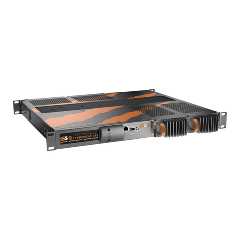
IS5 COMMUNICATIONS RAPTOR User manual

QG-Raptor-6-EN.doc i
© 2019 IS5 COMMUNICATIONS. CONFIDENTIAL & PROPRIETARY.
Quick Start Guide
RAPTOR™
Intelligent Cyber Secure Platform
Version 6, Dec 4, 2019
© 2019 iS5 Communications Inc. All rights reserved.

QUICK START GUIDE
QG-Raptor-6-EN.doc ii
© 2019 IS5 COMMUNICATIONS. CONFIDENTIAL & PROPRIETARY.
COPYRIGHT NOTICE
© 2019 iS5 Communications Inc. All rights reserved.
No part of this publication may be reproduced in any form without the prior written consent of iS5
Communications Inc. (iS5).
TRADEMARKS
iS5Com is a registered trademark of iS5. All other trademarks belong to their respective owners.
REGULATORY COMPLIANCE STATEMENT
Product(s) associated with this publication complies/comply with all applicable regulations. For more details,
refer to the Technical Specifications.
WARRANTY
iS5 warrants that all products are free from defects in material and workmanship for a specified warranty
period from the invoice date (5 years for most products). iS5 will repair or replace products found to be
defective within this warranty period including shipping costs. This warranty does not cover product
modifications or repairs done by persons other than iS5-approved personnel, and this warranty does not
apply to products that are misused, abused, improperly installed, or damaged by accident.
Refer to the Technical Specifications for the actual warranty period(s) of the product(s) associated with this
publication.
DISCLAIMER
Information in this publication is intended to be accurate. iS5 shall not be responsible for its use or
infringements on third parties because of the use of this publication. There may occasionally be unintentional
errors on this publication. iS5 reserves the right to revise the contents of this publication without notice.
CONTACT INFORMATION
iS5 Communications Inc.
5895 Ambler Dr, Mississauga, ON L4W 5B7, Canada
Tel: 1+ 905-670-0004 // Fax: 1+ 289-401-5206
Website: www.iS5Com.com
Technical Support
E-mail: support@iS5Com.com
Sales Contact
E-mail: sales@iS5Com.com

QG-Raptor-6-EN.doc v
© 2019 IS5 COMMUNICATIONS. CONFIDENTIAL & PROPRIETARY.
Contents
CHAPTER 1: INTRODUCTION ________________________________________________ 1
1.1 Purpose and Scope .............................................................................. 1
CHAPTER 2: COMMAND LINE INTERFACE _____________________________________ 2
2.1 Console Serial Connectivity ................................................................ 2
2.2 Logging into the Command Line Interface......................................... 4
2.3 Configuring the Switch......................................................................... 4
2.3.1 Configuring Admin Password ..................................................................... 4
2.3.2 Configuring Switch Name ........................................................................... 5
2.3.3 Configuring Switch Prompt ......................................................................... 5
2.4 Configuring IP Address........................................................................ 5
2.4.1 IP Address .................................................................................................. 5
2.4.2 Default Route.............................................................................................. 5
2.5 Saving Configuration............................................................................ 6
2.5.1 Save Configuration ..................................................................................... 6
2.5.2 Saving Configuration to USB...................................................................... 6
2.5.3 Restoring Configuration from USB ............................................................. 6
2.6 Software Upgrade from USB................................................................ 6
CHAPTER 3: WEB INTERFACE _______________________________________________ 7
3.1 Ethernet Connectivity to the Raptor from a Computer ..................... 7
3.2 Starting WebUI ...................................................................................... 8
3.2.1 Login ........................................................................................................... 8
3.2.2 Home Page................................................................................................. 9
3.3 Configuring the Switch Name and Prompt......................................... 9
3.4 IP Address Configuration................................................................... 10
3.4.1 VLAN Interface Basic Settings ................................................................. 10
3.4.2 IPv4 Interface Settings ............................................................................. 11
3.4.3 IP Route Configuration ............................................................................. 13
3.5 Saving and Restoring Configuration ................................................ 15
3.5.1 Save Configuration ................................................................................... 15
3.5.2 Saving configuration to USB..................................................................... 16
3.5.3 Restoring Configuration from USB ....................................................... 17
3.6 System Upgrade from USB ................................................................ 18

QUICK START GUIDE
QG-Raptor-6-EN.doc vi
© 2019 IS5 COMMUNICATIONS. CONFIDENTIAL & PROPRIETARY.
Figures
Figure 1: COM Port Connectivity ........................................................................................................................2
Figure 2: Device Manager, Ports ( COM & LPT ) ..............................................................................................3
Figure 3: Device Manager, Example of Ports Shown.........................................................................................3
Figure 4: PuTTY Configuration ...........................................................................................................................4
Figure 5: Ethernet/IP Connectivity ......................................................................................................................7
Figure 6: Login Screen .......................................................................................................................................8
Figure 7: Home Page..........................................................................................................................................9
Figure 8: System Settings Screen ......................................................................................................................9
Figure 9: VLAN Interface Basic Settings Screen..............................................................................................10
Figure 10: IPv4 Interface Settings Screen........................................................................................................11
Figure 11: IP Route Configuration Screen........................................................................................................13
Figure 12: Example of IP Route Configuration .................................................................................................14
Figure 13: Save configuration Screen ..............................................................................................................15
Figure 14: Save configuration Screen ..............................................................................................................16
Figure 15: Startup Configuration Restore Source Screen................................................................................17
Figure 16: System Upgrade Screen .................................................................................................................18

CHAPTER 1: INTRODUCTION
QG-Raptor-6-EN.doc 1
© 2019 IS5 COMMUNICATIONS. CONFIDENTIAL & PROPRIETARY.
Chapter
1
Introduction
This document explains how to use Command Line Interface (CLI) interface and Web user interface (UI) to
perform the following tasks:
•Login to the Raptor
•Create an IP address for VLAN #1
•Set password, switch name, banner name, and prompt
•Save configuration.
•Restore configuration
•Upgrade the Raptor
1.1 Purpose and Scope
This document covers the startup procedures and specifies the basic configuration commands. For more
information or support, email support@is5com.com.

CHAPTER 2: COMMAND LINE INTERFACE
QG-Raptor-6-EN.doc 2
© 2019 IS5 COMMUNICATIONS. CONFIDENTIAL & PROPRIETARY.
Chapter
2
Command Line Interface
2.1 Console Serial Connectivity
On your laptop, install a terminal emulator. A popular option is Putty.
A link to download Putty is https://www.chiark.greenend.org.uk/~sgtatham/putty/latest.html
Form a serial connection from your computer to the console port of the Raptor.
Figure 1: COM Port Connectivity
To determine the communications port being used on your laptop/computer, open the Device Manager (see
Figure 2 and Figure 3) .

CHAPTER 2: COMMAND LINE INTERFACE
QG-Raptor-6-EN.doc 3
© 2019 IS5 COMMUNICATIONS. CONFIDENTIAL & PROPRIETARY.
Figure 2: Device Manager, Ports ( COM & LPT )
Figure 3: Device Manager, Example of Ports Shown

QUICK START GUIDE
QG-Raptor-6-EN.doc 4
© 2019 IS5 COMMUNICATIONS. CONFIDENTIAL & PROPRIETARY.
Putty can be configured by selecting the type of connection, entering the port number, and setting the baud
rate.
Figure 4: PuTTY Configuration
Additional serial parameters can be configured in Putty by selecting the Serial category found at the bottom
of the Category panel.
The serial port configuration is as follows:
•Baud rate: 115200
•Data: 8
•Parity: none
•Stop: 1
•Flow Control: none
Once Putty has been set, click Open to launch a terminal.
2.2 Logging into the Command Line Interface
To access the command line interface (CLI) shell, at the iS5Com login prompt, use the user name admin
and password admin.
IS5FIRMWARE login: admin
Password: admin
iS5comm#
2.3 Configuring the Switch
2.3.1 Configuring Admin Password
iS5comm# configure terminal

CHAPTER 2: COMMAND LINE INTERFACE
QG-Raptor-6-EN.doc 5
© 2019 IS5 COMMUNICATIONS. CONFIDENTIAL & PROPRIETARY.
iS5comm(config)# username admin password Abcd123! privilege 15 confirm-password
Abcd123!
iS5comm(config)# exit
iS5commm#
2.3.2 Configuring Switch Name
iS5comm# configure terminal
iS5comm(config)# set switch-name XYZ
iS5comm(config)# exit
iS5comm#
2.3.3 Configuring Switch Prompt
iS5comm# configure terminal
iS5comm(config)# set prompt-name Prompt-XYZ
Prompt-XYZ(config)# end
Prompt-XYZ
2.4 Configuring IP Address
Speak with your Network Administrator to determine the values of the following parameters:
•IP Address
•IP Address Mask
•Default Route
2.4.1 IP Address
iS5comm# configure terminal
iS5comm(config)# interface vlan 1
iS5comm(config-if)# ip address <IP Address> <IP Address Mask>
iS5comm(config-if)# no shutdown
iS5comm(config-if)# exit
iS5comm(config)# exit
iS5comm#
2.4.2 Default Route
iS5comm# configure terminal
iS5comm(config)# ip route 0.0.0.0 0.0.0.0 192.168.32.254
iS5comm(config)# exit
iS5comm#

QUICK START GUIDE
QG-Raptor-6-EN.doc 6
© 2019 IS5 COMMUNICATIONS. CONFIDENTIAL & PROPRIETARY.
2.5 Saving Configuration
2.5.1 Save Configuration
iS5comm# write startup-config
Building configuration ...
[OK]
2.5.2 Saving Configuration to USB
iS5comm# copy startup-config usb
2.5.3 Restoring Configuration from USB
iS5comm# copy usb startup-config
2.6 Software Upgrade from USB
1. Rename sw-pack to “firmware-upgrade.tgz” and copy the file to the USB stick.
2. Power the Raptor and wait until system is running.
3. Insert USB stick into front panel USB connector.
iS5comm# firmware upgrade usb firmware_upgrade.tgz

CHAPTER 3: WEB INTERFACE
QG-Raptor-6-EN.doc 7
© 2019 IS5 COMMUNICATIONS. CONFIDENTIAL & PROPRIETARY.
Chapter
3
Web Interface
Raptor can be configured through Web User Interface from Web browsers. Web User Interface (Web UI)
allows the user to control various parameters at the System and Protocol level.
Before configuring the Raptor from a PC, confirm accessibility of Raptor’s firmware by pinging it from the PC.
3.1 Ethernet Connectivity to the Raptor from a Computer
Figure 5: Ethernet/IP Connectivity
An Ethernet cable must connect the switch and a computer. The computer interface should be assigned an
IP address on the 192.168.10.0/24 network.
An address of 192.168.10.100 with a subnet mask of 255.255.255.0 is one such suitable combination of an
IP address and submask to be assigned for the computer to be used in the connection.

QUICK START GUIDE
QG-Raptor-6-EN.doc 8
© 2019 IS5 COMMUNICATIONS. CONFIDENTIAL & PROPRIETARY.
3.2 Starting WebUI
Launch a web browser to enter the Raptor’s default IP address. The IP address of the Raptor’s interface is
192.168.10.1. Enter http://192.168.10.1 in the address bar of the web browser to access Raptor WebUI. The
Loginpage appears.
iS5com's Raptor product is compatible with Internet Explorer 8.0 or Mozilla Firefox 3.5 and above.
The screen capture of the Login screen is when Internet Explorer is used.
3.2.1 Login
Figure 6: Login Screen
Enter the User Name "admin" and Password "admin" and click Login.
This User Name and Password are used for accessing and configuring the switch through the Web UI. The
user name and password entered are validated at the switch end.
While browsing through the pages, the following Web design conventions are to be borne in mind.
•In web pages involving tables, the values to be configured are represented as blank cells or with a
drop-down menu for selecting the required value.
•A field entry with a * symbol displayed in a Web page denotes a mandatory field.
•For the read/write values in the table, there is provision to select a particular entry and modify it.
The LEDs displayed on the top of the pages denote the ports. A green light indicates that the port is up, and
a red light indicates that the port is down.

CHAPTER 3: WEB INTERFACE
QG-Raptor-6-EN.doc 9
© 2019 IS5 COMMUNICATIONS. CONFIDENTIAL & PROPRIETARY.
3.2.2 Home Page
After clicking Login, the Raptor Web GUI Home page appears.
Figure 7: Home Page
3.3 Configuring the Switch Name and Prompt
To configure the switch through Web UI, execute the following steps:
In the Home page, go to System > System Information > System Settings
Figure 8: System Settings Screen
1. Configure any of the following fields.
Fields
•Switch Name—enter the name for identifying the device. The default value is
iS5. This value range is a string of size 15.
•Prompt Name—enter the prompt name to be used. The default value is iS5.
•Banner Name—enter the banner name to be used. The default
value is
RAPTOR iBiome OS.
•System Contact—enter the contact person details for this managed node.

QUICK START GUIDE
QG-Raptor-6-EN.doc 10
© 2019 IS5 COMMUNICATIONS. CONFIDENTIAL & PROPRIETARY.
This value range is a string of size 50. The default value is iS5com.
•System Name—enter the system name. The default value is iS5com.
•System Location—enter the physical location of this node. This value range
is a string of size
50
. The default value is iS5com.
2. Click Apply.
3.4 IP Address Configuration
Go to Layer 3 Management > IP > VLAN Interface. VLAN Interface Basic Settings page appears.
3.4.1 VLAN Interface Basic Settings
Figure 9: VLAN Interface Basic Settings Screen
Screen Objective
This screen allows the user to configure the basic settings of the VLAN interface.
Navigation Layer 3 Management > IP > VLAN Interface
Fields
1. From the second entry panel which begins with the Select column.
•Select—select the VLAN Interface for which configuration needs to be modified
or deleted. In this case it will be VLAN interface #1.
•VLAN Interface—enter “1”.
•Switch—default.
•Admin State—select “Up from the dropdown list.
•
IPv4 Enabled State—select the status of IPv4 on the interface. The default

CHAPTER 3: WEB INTERFACE
QG-Raptor-6-EN.doc 11
© 2019 IS5 COMMUNICATIONS. CONFIDENTIAL & PROPRIETARY.
option is UP. Choose UP.
•Operating State—choose UP.
•Proxy ARP—select the Proxy ARP admin status for the interface. The default
option is Disabled. Select Disabled.
•MTU—enter 1500.
2. Click
Apply
.
3.4.2 IPv4 Interface Settings
For IPv4 Interface, go to Layer 3 Management > IP > IPV4 AddrConf. IPv4 Interface Settings page
appears.
Figure 10: IPv4 Interface Settings Screen
Screen Objective This screen allows the user to configure the settings of the IPv4 interface
Navigation
Layer3 Management
>
IP
>
IPv4 Addr Conf
Fields •Select—select the VLAN Interface for which configuration needs to be
modified or deleted.
•VLAN Interface—enter the VLAN/VFI ID for the Interface to be created.
The value ranges from 1 to 65535.
−<vlan –id>—this is a unique value that represents the specific
VLAN. This value ranges from 1 to 4094
−<vfi-id>—VFI ID is a VLAN created in the system which contains
Pseudo wires and Attachment Circuits as member ports. This
creates a logical LAN for the VPLS service. This value ranges from
4096 to 65535
The VLAN ID 4095 is reserved and may be used to indicate a
wildcard match for the VID in management operations or Filtering
Database entries.
The theoretical maximum for the maximum number of VFI is 65535
but the actual number of VFI supported is a sizing constant. Based
on this, the maximum number of VFI ID accepted in the
management interface is restricted. For example, if 100 VFIs are
supported, the maximum number of VFI supported will be restricted
to maximum number of VLANs + 100. An error message is

QUICK START GUIDE
QG-Raptor-6-EN.doc 12
© 2019 IS5 COMMUNICATIONS. CONFIDENTIAL & PROPRIETARY.
displayed for any value beyond this range.
•Switch—default.
•Admin State—select the Admin Status of the VLAN interface. The default
option is Down. The list contains:
−Up—sets the IP interface administratively up. After Configuring the
IP address, the interface can be made admin UP.
−Down—sets the IP interface administratively down.
•IPv4 Enabled State—select the status of IPv4 on the interface. The
default option is UP. The list contains:
−UP—enables IPv4 on the specified interface.
−Down—disables IPv4 on the specified interface.
•Operating State—displays the current operational status of the VLAN
interface. The list contains:
−Up—specifies that the interface is operationally up and ready to
transmit and receive network traffic.
−Down—specifies that the interface is operationally down.
•Proxy ARP—select the Proxy ARP admin status for the interface. The
default option is Disabled. The list contains:
−Enabled—enables Proxy ARP feature for the interface.
−Disabled—disables Proxy ARP feature for the interface.
•MTU—enter the Maximum Transmission Unit (MTU). The MTU for the
interface as shown to the higher interface sub-layer (this value should not
include the encapsulation or header added by the interface). If IP is
operating over the interface, then this value indicates the IP MTU over this
interface. The default value is 1500. This value ranges from 46 to 9216.
To configure the MTU value, the Admin State of the interface
should be Down.
Buttons •Create—adds and saves new configuration
•Reset—resets to default value for respective fields and discards all user
inputs
•Apply—modifies attributes for the selected entry and saves the changes
•
Delete
—deletes the selected entry
1. In the appropriate fields, enter IP Address and Subnet Mask address for your network. Consult your
network administrator if you do not know these values.
2. Click Modify.

CHAPTER 3: WEB INTERFACE
QG-Raptor-6-EN.doc 13
© 2019 IS5 COMMUNICATIONS. CONFIDENTIAL & PROPRIETARY.
3.4.3 IP Route Configuration
For IP Route Configuration, go to Layer 3 Management > IP > IP Route. IP Route Configuration appears.
Figure 11: IP Route Configuration Screen
Screen Objective This screen allows the user to configure IP route information.
Navigation Layer 3 Management > IP > IP route
Fields •Select—select the destination network for which configuration needs to be
modified or deleted.
•Destination Network—enter the destination IP address of the route. It
denotes the Network Address for which the route is being added.
•Subnet Mask—enter the subnet mask for the Destination Network address.
•Gateway—enter the Next Hop gateway to reach the Destination Network.
•Interface—select the outgoing interface through which the Destination Network
is reachable.
The interface ID can be created from the VLAN Interface Basic Settings
screen.
•Switch—default
•Distance (Metric)—enter the Metric value of the destination. The semantics of
this metric are determined by the routing-protocol. The value ranges from 1 to
255. The default value is 1.
•Routing Protocol—displays the status of the routing protocol through which
the route was learnt if the route is not a directly connected network or a static

QUICK START GUIDE
QG-Raptor-6-EN.doc 14
© 2019 IS5 COMMUNICATIONS. CONFIDENTIAL & PROPRIETARY.
route.
Buttons Add—adds and saves new configuration
Reset—resets to default value for respective fields and discards all user inputs
Apply—modifies attributes for the selected entry and saves the changes
Only static routes can be deleted or modified.
Delete—deletes the selected entry.
Perform the following:
1. You will need two routes: one route to your network and a default route to your control center. Once
these routes are established, a remote user can configure the switch for proper configuration.
2. You will need to configure VLAN #1 to use the default gateway. This route may already be in your list.
The destination network should be the network for the IP Address configured in section 0, the subnet
mask, the interface should be “vlan1”, the switch option should be “default” ,and the metric should be “0”.
3. Click Add.
4. Configure the default gateway. The destination network should be 0.0.0.0, the subnet mask should be
0.0.0.0, and the gateway should be the gateway router IP address. Consult with your administrator if you
do not know this value. Leave the interface blank. The switch should be “default” and the distance should
be 0.
5. Click Add. The result should be as shown below. Click Apply.
Figure 12: Example of IP Route Configuration

CHAPTER 3: WEB INTERFACE
QG-Raptor-6-EN.doc 15
© 2019 IS5 COMMUNICATIONS. CONFIDENTIAL & PROPRIETARY.
3.5 Saving and Restoring Configuration
3.5.1 Save Configuration
The Save configuration page allows saving of essential configuration.
In the Home page, go to System > Save and Restore > Save. Save configuration page appears.
This procedure will allow the working configuration of the switch be saved to flash. Saving the configuration
to flash will ensure that the configuration is preserved following power outages or reboots.
Figure 13: Save configuration Screen
Screen Objective This screen allows the user to save the current configuration.
Navigation
System > Save and Restore > Save
1. Set the fields as follows.
•Save option—select Flash Save.
•Save Format—select either MIB OID or Script. Script format is human-
readable.
•File Name—The default file name where the Switch configurations are saved
is iss.conf. Use the default file name.
This file name is used for saving the switch configuration, irrespective of
the configuration Save Option which can be Flash or Remote Save.
2. Click
Apply
to save the changes.

QUICK START GUIDE
QG-Raptor-6-EN.doc 16
© 2019 IS5 COMMUNICATIONS. CONFIDENTIAL & PROPRIETARY.
3.5.2 Saving configuration to USB
The Save configuration page allows saving of essential configuration.
In the Home page, go to System > Save and Restore > Save. Save configuration page appears.
Figure 14: Save configuration Screen
Screen Objective This screen allows the user to save the current configuration of the switch in a file.
When save operation is initiated, all configurations made through CLI, SNMP, or
WEB interfaces are saved in a file.
There are two options to save the configuration data: Flash Save and Remote
Save. A Flash Save configures that the configurations need to be saved in Flash,
whereas a Remote Save specifies that the configurations need to be saved to a
remote system.
Navigation System > Save and Restore > Save
1. Set the fields as follows.
•Save option—select USB Save.
•Save Format—select either MIB OID or Script. Script format is human-
readable.
•File Name—enter the name of the file in which the Switch configurations are to
be saved. The default file name where the Switch configurations are saved is
iss.conf. All configurations are saved in a single configuration file only.
This file name is used for saving the Switch configuration, irrespective of
the configuration Save Option which can be Flash or Remote Save.
2. Insert the USB fob into the USB port on the front of the switch.
3. Click Applyto save the changes.
Table of contents
Other IS5 COMMUNICATIONS Control Unit manuals
Popular Control Unit manuals by other brands

EVC electronic
EVC electronic OLS300 manual

Stahl
Stahl IS1+ 9475/32-04-72 Series operating instructions

Logic Controls
Logic Controls LS6000 installation guide

Emerson
Emerson Fisher ME00124272 Instruction manual supplement

W.E.S.T. Elektronik
W.E.S.T. Elektronik POS-124-A-PDP Technical documentation

Campbell
Campbell CR300 series Application note