TLV BD800 User manual

172-65694MA-01 (BD800) 25 July 2018
Bypass Blow Valve
BD800
Copyright © 2018 by TLV CO., LTD.
All rights reserved

172-65694MA-01 (BD800) 25 Jul 2018
1
Contents
Introduction ........................................................................1
Safety Considerations........................................................2
Specifications.....................................................................4
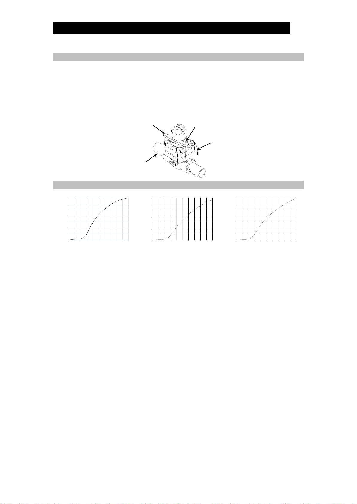
Configuration......................................................................4
Installation..........................................................................5
Operation ...........................................................................6
Maintenance.......................................................................8
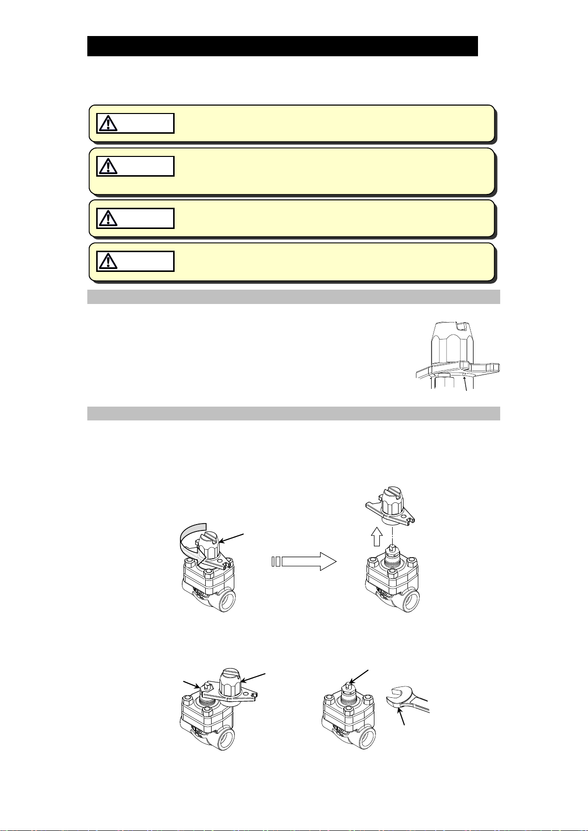
Disassembly/Reassembly................................................10
Cleaning the Valve Seat Section......................................13
Troubleshooting ...............................................................14
Product Warranty .............................................................15
Introduction
Thank you for purchasing the bypass blow valve.
This product has been thoroughly inspected before being shipped from the factory.
When the product is delivered, before doing anything else, check the specifications
and external appearance to make sure nothing is out of the ordinary. Also be sure to
read this manual carefully before use and follow the instructions to be sure of using
the product properly.
The bypass blow valve has excellent durability and reliable sealing
performance in addition to a structure which can clean its seating surfaces in a
simple operation. In support of this long-life product, the main components of the
valve are replaceable.
In conventional valves, when dust or scale adheres to the seating surface of the
valve seat section, leakage occurs eventually leading to erosion, and ultimately the
valve will no longer function properly.
This bypass blow valve utilizes a special material for the valve stem and valve seat
sections and together with its unique form, rotational contact between the seating
surfaces scrapes off scale and restores the sealing performance of the valve.
The proven special material, combined with the unique cleaning mechanism reduces
the burden of valve maintenance and operation.
If detailed instructions for special order specifications or options not contained in this
manual are required, please contact for full details.
This instruction manual is intended for use with the model(s) listed on the front cover.
It is necessary not only for installation but for subsequent maintenance,
disassembly/reassembly and troubleshooting. Please keep it in a safe place for
future reference.

172-65694MA-01 (BD800) 25 Jul 2018
2
Safety Considerations
•Read this section carefully before use and be sure to follow the instructions.
•Installation, inspection, maintenance, repairs, disassembly, adjustment and valve
opening/closing should be carried out only by trained maintenance personnel.
•The precautions listed in this manual are designed to ensure safety and prevent
equipment damage and personal injury. For situations that may occur as a result
of erroneous handling, three different types of cautionary items are used to
indicate the degree of urgency and the scale of potential damage and danger:
DANGER, WARNING and CAUTION.
•The three types of cautionary items above are very important for safety: be sure to
observe all of them as they relate to installation, use, maintenance, and repair.
Furthermore, TLV accepts no responsibility for any accidents or damage occurring
as a result of failure to observe these precautions.
Symbols
Indicates a DANGER, WARNING or CAUTION item.
DANGER
Indicates an urgent situation which poses a threat of death or
serious injury
WARNING
Indicates that there is a potential threat of death or serious injury
CAUTION
Indicates that there is a possibility of injury or equipment/product
damage
WARNING
DO NOT use for any other fluids than applicable fluids. DO
NOT use for toxic, flammable or otherwise hazardous fluids.
This product is for intended use only.
Improper use may result in such hazards as damage to the product
or malfunctions that may lead to serious accidents.
CAUTION
Install properly and DO NOT use this product outside the
recommended operating pressure, temperature and other
specification ranges.
Improper use may result in such hazards as damage to the product
or malfunctions that may lead to serious accidents. Local
regulations may restrict the use of this product to below the
conditions quoted.
Take measures to prevent people from coming into direct
contact with product outlets.
Failure to do so may result in burns or other injury from the
discharge of fluids.
Safety considerations continued on next page

172-65694MA-01 (BD800) 25 Jul 2018
3
CAUTION
When disassembling or removing the product, wait until the
internal pressure equals atmospheric pressure and the surface
of the product has cooled to room temperature.
Disassembling or removing the product when it is hot or under
pressure may lead to discharge of fluids, causing burns, other
injuries or damage.
Before using the product, ensure piping is cleaned and flushed to
remove foreign matter.
Failure to observe this precaution may cause leakage from the valve
seat.
Be sure to use only the recommended components when
repairing the product, and NEVER attempt to modify the
product in any way.
Failure to observe these precautions may result in damage to the
product and burns or other injury due to malfunction or the
discharge of fluids.
Do not use excessive force when connecting threaded pipes to
the product.
Over-tightening may cause breakage leading to fluid discharge,
which may cause burns or other injury.
Do not place weight on top of the spanner cap. The product is
not designed to be climbed on by people.
Failure to observe this precaution may result in damage to the
spanner cap or injury.
When using the spanner cap, be sure to use heat-resistant
gloves.
Disassembling or removing the product when it is hot or under
pressure may lead to discharge of fluids, causing burns, other
injuries or damage.
Use only under conditions in which no freeze-up will occur.
Freezing may damage the product, leading to fluid discharge, which
may cause burns or other injury.
Use only under conditions in which no water hammer will
occur.
The impact of water hammer may damage the product, leading to
fluid discharge, which may cause burns or other injury.

172-65694MA-01 (BD800) 25 Jul 2018
4
Specifications
DO NOT use for any other fluids than applicable fluids. DO NOT use for
toxic, flammable or otherwise hazardous fluids. This product is for
intended use only. Improper use may result in such hazards as damage
to the product or malfunctions that may lead to serious accidents.
WARNING
Install properly and DO NOT use this product outside the recommended
operating pressure, temperature and other specification ranges.
Improper use may result in such hazards as damage to the product or
malfunctions which may lead to serious accidents. Local regulations
may restrict the use of this product to below the conditions quoted.
CAUTION
Use only under conditions in which no freeze-up will occur. Freezing
may damage the product, leading to fluid discharge, which may cause
burns or other injury.
CAUTION
Refer to the product nameplate for detailed specifications.
Model
Production Lot No.
Max. Operating Pressure (PMO) /
Max. Operating Temperature (TMO)
Nominal Diameter
Valve Class/
Body Material
Configuration
NOTE: Gland packing removal
tool is available on request.
Consult TLV for details.
No.
Name
M*
R*
G*
T*
No.
Name
M*
R*
G*
T*
1
Body
8
Gland Holder
2
Bonnet
9
Spanner Cap
3
Valve Seat
10
Bonnet Bolt
4
Valve Seat Gasket
11
Bonnet Nut
5
Bonnet Gasket
12
Flange/Socket
6
Valve Stem
13
Nameplate
7
Gland Packing
14
Gland Packing Removal Tool
*Replacement parts are available only in the following kits:
M = Maintenance kit
R = Repair kit
G = Gland packing
T = Gland packing removal tool

172-65694MA-01 (BD800) 25 Jul 2018
5
Installation
DO NOT use for any other fluids than applicable fluids. DO NOT use for
toxic, flammable or otherwise hazardous fluids. This product is for
intended use only. Improper use may result in such hazards as damage
to the product or malfunctions that may lead to serious accidents.
WARNING
Before using the product, ensure piping is cleaned and flushed to
remove foreign matter. Failure to observe this precaution may cause
leakage from the valve seat.
CAUTION
Install properly and DO NOT use this product outside the recommended
operating pressure, temperature and other specification ranges.
Improper use may result in such hazards as damage to the product or
malfunctions which may lead to serious accidents. Local regulations
may restrict the use of this product to below the conditions quoted.
CAUTION
Take measures to prevent people from coming into direct contact with
product outlets. Failure to do so may result in burns or other injury from
the discharge of fluids.
CAUTION
Do not use excessive force when connecting threaded pipes to the
product. Over-tightening may cause breakage leading to fluid
discharge, which may cause burns or other injury.
CAUTION
Installation, inspection, maintenance, repairs, disassembly, adjustment and valve
opening/closing should be carried out only by trained maintenance personnel.
1. When the product is shipped from the factory, the valve stem is positioned in the
lowest, valve-closed position.
2. Before installation, be sure to remove all protective seals.
3. Before installing the product, open the inlet valve and blow out the piping to
remove any piping scraps, dirt and oil. Close the inlet valve after blowdown.
4. Install the product so the arrow on the body is pointing in the direction of flow.
5. Install outlet piping.
If there is a problem, determine the cause using the “Troubleshooting” section in this
manual.

172-65694MA-01 (BD800) 25 Jul 2018
6
Operation
DO NOT use for any other fluids than applicable fluids. DO NOT use for
toxic, flammable or otherwise hazardous fluids. This product is for
intended use only. Improper use may result in such hazards as damage
to the product or malfunctions that may lead to serious accidents.
WARNING
Install properly and DO NOT use this product outside the recommended
operating pressure, temperature and other specification ranges.
Improper use may result in such hazards as damage to the product or
malfunctions which may lead to serious accidents. Local regulations
may restrict the use of this product to below the conditions quoted.
CAUTION
Take measures to prevent people from coming into direct contact with
product outlets. Failure to do so may result in burns or other injury from
the discharge of fluids.
CAUTION
When using the spanner cap, be sure to use heat-resistant gloves.
Disassembling or removing the product when it is hot or under pressure
may lead to discharge of fluids, causing burns, other injuries or damage.
CAUTION
Removing the Spanner Cap
Remove the spanner cap by turning it counter-clockwise.
Spanner Cap
Adjusting the Valve Aperture
Place the spanner cap as shown in Figure A, adjust the valve aperture by turning the
valve stem. The adjustment can also be made by using the narrow open end of the
spanner cap as shown in Figure B.
NOTE: The valve stem is in a fully closed position when shipped from the factory and
is tightened to a specific torque. Depending on the environment in which the product
is installed, the valve stem may be difficult to adjust. In such a case, use an
adjustable wrench or socket wrench to adjust the valve stem. This will make the
valve steam easy to adjust with the spanner cap.
Figure A
Valve Stem
Figure B
NOTE: The valve stem can also be
adjusted with an adjustable wrench,
socket wrench, etc.
Distance across flats: 7 mm (9/32 in)
Restoring the Spanner Cap
Once the adjustment is made, replace the spanner cap.
This prevents unintentional change of the valve aperture. As the valve stem is
covered by the spanner cap, it is protected against rainwater or foreign matter,
reducing the likelihood of the valve stem sticking.

172-65694MA-01 (BD800) 25 Jul 2018
7
Preventing Erroneous Operation of the Valve Stem
The product is equipped with a function that prevents erroneous operation of the
valve. A hole in the spanner cap allows the spanner cap to be fixed by passing a
wire/steel wire and tightening it around the piping or flange as shown below.
Restricting movement of the spanner cap prevents the valve from being operated
erroneously.
Spanner Cap Hole
Wire/
Steel Wire
Piping
Relation between CV / Kvs Values and No. of Turns of the Valve Stem
3.5
3
2.5
2
1.5
1
0.5
00123 4 5
3.5
3
2.5
2
1.5
1
0.5
00123 4 5
3.5
3
2.5
2
1.5
1
0.5
00123 4 5
Cv(US)
No. of turns*
Cv(UK)
KV
No. of turns* No. of turns*
*No. of turns of the valve stem is based on the fully closed position

172-65694MA-01 (BD800) 25 Jul 2018
8
Maintenance
Take measures to prevent people from coming into direct contact with
product outlets. Failure to do so may result in burns or other injury from
the discharge of fluids.
CAUTION
Be sure to use only the recommended components when repairing the
product, and NEVER attempt to modify the product in any way. Failure to
observe these precautions may result in damage to the product or burns
or other injury due to malfunction or the discharge of fluids.
CAUTION
Do not place weight on top of the spanner cap. The product is not
designed to be climbed on by people. Failure to observe this precaution
may result in damage to the spanner cap or injury.
CAUTION
When using the spanner cap, be sure to use heat-resistant gloves.
Disassembling or removing the product when it is hot or under pressure
may lead to discharge of fluids, causing burns, other injuries or damage.
CAUTION
Periodic Inspection
Periodic inspection for the following points is recommended at least twice per year:
・Leakage when the valve is fully closed
・Leakage from the gland holder
The spanner cap has a blow hole at the bottom. Fluid jets
from the hole when there is leakage from the gland.
Take safety precautions when performing this inspection.
・Leakage from the bonnet gasket
Retightening of the Gland Section
The gland holder can be retightened. When fluid leaks from the gland section,
retighten the gland holder by following the steps below. Make sure that the valve is in
the fully closed position when tightening the gland section.
1. Remove the spanner cap by turning it counter-clockwise.
Spanner Cap
2. Tighten the gland holder.
The gland holder can be tightened with the spanner cap as well as a spanner
wrench with a distance across flats of 22 mm (7/8in). Tighten as necessary.
Spanner Cap
Spanner Wrench
Valve Stem
Gland Holder
Blow hole

172-65694MA-01 (BD800) 25 Jul 2018
9
NOTE: Once leakage from the upper part of the gland holder has stopped, do not
tighten any further. Make sure that the valve stem can still turn after the
gland holder is tightened. Contact TLV if leakage does not stop even after
retightening.
3. After retightening is complete, replace the spanner cap.

172-65694MA-01 (BD800) 25 Jul 2018
10
Disassembly/Reassembly
NEVER apply direct heat to the float. The float may explode due to
increased internal pressure, causing accidents leading to serious injury
or damage to property and equipment.
WARNING
Use hoisting equipment for heavy objects (weighing approximately
20 kg (44 lb) or more). Failure to do so may result in back strain or other
injury if the object should fall.
CAUTION
When disassembling or removing the product, wait until the internal
pressure equals atmospheric pressure and the surface of the product
has cooled to room temperature. Disassembling or removing the
product when it is hot or under pressure may lead to discharge of fluids,
causing burns, other injuries or damage.
CAUTION
Use the following procedures to remove components. Use the same procedures in
reverse to reassemble. (Installation, inspection, maintenance, repairs, disassembly,
adjustment and valve opening/closing should be carried out only by trained
maintenance personnel.)
Disassembly/Reassembly of the Body/Bonnet Section
Part
During Disassembly
During Reassembly
Spanner Cap
Unscrew and remove from the bonnet
Screw onto the bonnet
Bonnet Nut
Remove with a socket wrench
Consult the table of tightening torques
and tighten to the proper torque
Bonnet
Pull up and remove
Align the embossed lettering on the
bonnet and body and reattach
NOTE: When assembling the bonnet to the body, tighten the bonnet nuts, making sure that
the valve stem is seated on the valve seat with no built-up of rust and scale.
When tightening the bonnet nuts, tighten all of them evenly and gradually to the proper
torque to avoid uneven tightening. When the secondary side of the product is open to
the atmosphere, visually check whether fluid is leaking on the secondary side.
Contact TLV in the event leakage does not stop.
Disassembly/Reassembly of the Bonnet Section
Part
During Disassembly
During Reassembly
Gland Holder
Remove with a socket wrench
Consult the table of tightening torques
and tighten to the proper torque
Valve Stem
Replace only when necessary;
Unscrew from the bonnet
Screw into the bottom part of the
bonnet
Gland Packing
Replace only when necessary;
see the “Replacing the Gland
Packing” section for replacement
Reassemble as shown in the
“Replacing the Gland Packing”
section
Disassembly/Reassembly of the Body Section
Part
During Disassembly
During Reassembly
Bonnet
Gasket
Remove the gasket and clean
sealing surfaces
Replace with a new gasket
Valve Seat
Replace with a socket wrench only
when necessary
Consult the table of tightening torques
and tighten to the proper torque
Valve Seat
Gasket
Remove the gasket and clean
sealing surfaces
Replace with a new gasket; coat
surfaces with anti-seize

172-65694MA-01 (BD800) 25 Jul 2018
11
Table of Tightening Torques
Part Name
Torque
Distance Across Flats
N⋅m
(lbf⋅ft)
mm
(in)
Bonnet Nut
80
(59)
17
(21/32)
Gland Holder
60
(44)
22
(7/8)
Valve Seat
80
(59)
21
(13/16)
NOTE:
-Coat all threaded portions with anti-seize.
-
If drawings or other special documentation were supplied for the
torque given there takes precedence over values shown here.
(1 N⋅m ≈10 kg⋅cm)
Replacing the Gland Packing
1. Remove the valve stem then the gland holder from the bonnet.
Gland Holder
Bonnet
Valve Stem
2. Insert gland packing removal tool (A) into the bonnet, then screw removal tool (B) into
removal tool (A).
When removal tools (A) and (B) are inserted to the bonnet, the gland packing is caught by
the tip of removal tool and can be removed by lifting up the removal tool. Make sure to
remove dust and scale from inside the bonnet.
Removal Tool (B)
Removal Tool (A)
Gland
Packing
3. Reinsert the valve stem into the bonnet, then insert new gland packing into the bonnet.
Align the gland packing so that the stickers face each other. After the gland packing is
inserted, place removal tool (A) on top of the gland packing, and push the gland packing
into position by tapping on removal tool (A) with a plastic mallet. Remove removal tool (A),
replace the gland holder and tighten it to the proper torque.
Removal Tool (A)
Gland Packing Plastic Mallet
Removal Tool (A)

172-65694MA-01 (BD800) 25 Jul 2018
12
Exploded View
Spanner Cap
Bonnet Nut
Gland Holder
Gland Packing*
Bonnet
Valve Stem
Bonnet Gasket
Valve Seat
Valve Seat Gasket
Bonnet Bolt
Body
*Inlaid in the bonnet

172-65694MA-01 (BD800) 25 Jul 2018
13
Cleaning the Valve Seat Section
When disassembling or removing the product, wait until the internal
pressure equals atmospheric pressure and the surface of the product
has cooled to room temperature. Disassembling or removing the
product when it is hot or under pressure may lead to discharge of fluids,
causing burns, other injuries or damage.
CAUTION
Take measures to prevent people from coming into direct contact with
product outlets. Failure to do so may result in burns or other injury from
the discharge of fluids.
CAUTION
When scale adheres to the valve seat section, sealing is inhibited, causing fluid
leakage that affects the work environment.
Restore sealing performance and eliminate fluid leakage by following the steps
described below.
The figure below illustrates scale accumulation between the valve seat and valve
stem resulting in the valve not being able to fully close.
1. Remove the spanner cap.
2. Turn the valve stem counter-clockwise one to two times.
3. Turn the valve stem clockwise (right rotation) until it cannot be turned any further.
4. Repeat steps 2 and 3 two to three times. When the secondary side of the product
is open to the atmosphere, visually check whether fluid is leaking on the
secondary side after performing step 3.
5. When no fluid is leaking and the valve closes fully, cleaning is complete.
If leakage still occurs, repeat steps 2 and 3 another two to three times.
Turn the valve stem
counter-clockwise Scale is scraped off the valve seat
when turning the valve stem back
clockwise
Cleaning is complete if no
leakage occurs after closing the
valve again
Turn the valve stem counter-
clockwise again
Scale

172-65694MA-01 (BD800) 25 Jul 2018
14
Troubleshooting
NEVER apply direct heat to the float. The float may explode due to
increased internal pressure, causing accidents leading to serious injury
or damage to property and equipment.
WARNING
When disassembling or removing the product, wait until the internal
pressure equals atmospheric pressure and the surface of the product
has cooled to room temperature. Disassembling or removing the
product when it is hot or under pressure may lead to discharge of fluids,
causing burns, other injuries or damage.
CAUTION
When the product fails to operate properly, use the following table to locate the
cause and remedy.
Problem
Cause
Remedy
Fluid is leaking from
the outlet (even)
when the valve is
closed
The valve stem is not tightened
sufficiently
・
Place the spanner on the flat
surfaces of the valve stem and
tighten it to the proper torque
(16 N⋅m (12 lbf⋅ft)
・
Tighten the spanner cap with a
spanner to the proper torque
(16 N⋅m (12 lbf⋅ft)
The sealing surfaces of the valve
seat and valve stem are damaged
or clogged with rust and scale
(erosion, corrosion, etc.), clean
those surfaces
Clean the valve seat and valve
stem; if leakage does not stop after
cleaning, replace with a new valve
seat and/or valve stem (contact
TLV)
Fluid is leaking
from the gland
section
The gland holder is loosened
Retighten the gland holder, clean
or replace with new parts (contact
TLV)
The valve stem
does not move
The valve stem is clogged with
rust and scale
Clean or replace with a new valve
stem
Fluid is leaking from
a place other than
the outlet
・
Fluid is leaking from between
the bonnet and body
・Gasket deterioration or damage
・The gasket sealing surfaces of
the body and bonnet are
damaged or clogged with rust
and scale
Replace with new gasket(s)
Improper tightening torques were
used
Tighten to the proper torque
The valve stem and
the valve seat
frequently become
damaged
Water hammer has occurred
・
Check whether the valve stem
is over-tightened; if the valve
stem is deteriorated or
damaged, replace with a new
valve seat and/or valve stem
(contact TLV)
・Check and correct the piping
NOTE: When replacing parts with new, use the parts list for reference, and replace with parts
from the maintenance kit, repair kit, etc. Please note that replacement parts are only
available as part of a replacement parts kit.

172-65694MA-01 (BD800) 25 Jul 2018
15
Product Warranty
1. Warranty Period
One year following product delivery.
2. Warranty Coverage
TLV CO., LTD. warrants this product to the original purchaser to be free
from defective materials and workmanship. Under this warranty, the product
will be repaired or replaced at our option, without charge for parts or labor.
3. This product warranty will not apply to cosmetic defects, nor to any
product whose exterior has been damaged or defaced; nor does it apply in
the following cases:
1) Malfunctions due to improper installation, use, handling, etc., by other
than TLV CO., LTD. authorized service representatives.
2) Malfunctions due to dirt, scale, rust, etc.
3) Malfunctions due to improper disassembly and reassembly, or
inadequate inspection and maintenance by other than TLV CO., LTD.
authorized service representatives.
4) Malfunctions due to disasters or forces of nature.
5) Accidents or malfunctions due to any other cause beyond the control of
TLV CO., LTD.
4. Under no circumstances will TLV CO., LTD. be liable for consequential
economic loss damage or consequential damage to property.
* * * * * * *
For Service or Technical Assistance:
Contact your representative or your regional office.
Manufacturer
881 Nagasuna, Noguchi
Kakogawa, Hyogo 675-8511, JAPAN
Tel: 81-(0)79 - 427 - 1800
Table of contents
Other TLV Control Unit manuals