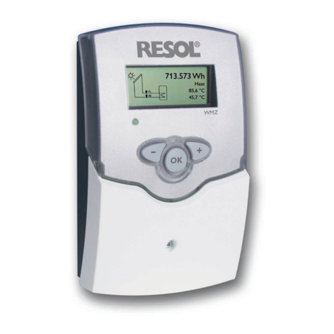
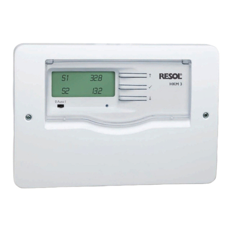
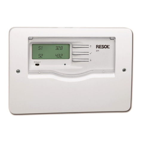
Resol DeltaSol ES User manual

Thanks for buying a RESOL product.
Read this manual carefully to get the best performance from this unit.
RESOL DeltaSol
®ES
Mounting
Connection
Handling
Fault localization
Examples
www.resol.de
DeltaSol
®ES
B
manual
48000770
*48000770*

© RESOL DeltaSol ES_07152.monen.indd
|2
DeltaSol
®ES
Security advice
Please pay attention to the following security advice in or-
der to avoid danger and damage to people and property.
This product is to be used in accordance with its intended
use only (see page 3).
Instructions
Attention should be paid
- to the statutory provisions for prevention of industrial
accidents,
- to the statutory provisions for environmental protec-
tion,
- to the Health and Safety at Work Act 1974
- to Part P of the Building Regulations 2005
- to BS7671 Requirements for electrical installations and
relevant safety regulations of DIN, EN, DVGW,TRGI,TRF
and VDE.
This instruction is exclusively addressed to authorised
skilled personnel.
- Only qualified electricians should carry out electrical
works.
- Initial installation should be effected by named qualified
personnel
Declaration of conformity
We, RESOL Elektronische Regelungen GmbH, D-45527
Hattingen, declare under our sole responsibility that our
product DeltaSol ES complies with the following stan-
dards:
EN 55 014-1
EN 60 730-1
According to the regulations of the above directives, the
product is labelled with :
89/336/EWG
73/ 23/EWG
Hattingen, 07.07.2006
RESOL Elektronische Regelungen GmbH,
ppa. Gerald Neuse
Contents
Imprint .................................................................................2
Security devices...................................................................2
Technical data and function survey ...................................3
1. Installation .............................................................4
1.1 Mounting.................................................................................. 4
1.2 Electrical wiring...................................................................... 4
1.2.1 Connection survey ................................................................ 4
1.2.2 Actuators................................................................................. 5
1.2.3 Bus............................................................................................. 5
1.2.4 Sensors..................................................................................... 6
1.2.5 Power connection.................................................................. 6
2 Operation and function ........................................7
2.1 Adjustment buttons .............................................................. 7
2.2 System monitoring display ................................................... 7
2.2.1 Channel indication................................................................. 7
2.2.2 Tool bar.................................................................................... 7
2.2.3 System screen......................................................................... 8
2.3 Blinking codes......................................................................... 8
2.3.1 System screen blinking codes.............................................. 8
2.3.2 LED blinking codes................................................................ 8
3. Commissioning......................................................9
4. Control parameter and indication channels ....10
4.1 Channel overview................................................................10
4.2.1-7 Indication channels ..............................................................18
4.3.1-15 Adjustment channels........................................................... 19
5. Tips for fault localization....................................24
5.1 Miscellaneous........................................................................ 25
6. Accessory .............................................................27
Errors an technical changes excepted.

© RESOL DeltaSol ES_07152.monen.indd
3 |
DeltaSol
®ES
155,0
220,0
202,0
12,0
62,0
Technical data
Housing: plastic, PC-ABS and PMMA
Protection type:
IP 20 / DIN 40 050
Environmental-temp.: 0 ...40 °C
Size: 220 x 155 x 62 mm
Mounting: wall mounting, mounting
into patch-panels is possible
Display: multi-functional combined
display with illuminated background,
stored system sketches and pictograms,
a 4-digit alpha-numerical 16-segment
display and a 4-digit numerical 7-seg-
ment display as well as a 2 coloured
LED. The controller can be equipped
optionally with an illuminated 4-digit
LC-text display.
Operation: by 3 pushbuttons in the
front of the housing
• 36basicsolarsystemsselectable
• illuminated system-monitoring
display
• pumpspeedcontrol, solar opera-
ting hours counter and heat quan-
tity measurement
• 10sensorinputs
• 6relayoutputs
• functioncontrol
• VBus®
Electrostatic discharge can
cause damages of electronic
components
Attention: high-voltaged com-
ponents
Functions: solar- and heating con-
troller with pre-programmed and
selectable system schemes, just as:
standard solar system,2-store systems,
east-/west collectors, heating circuit
back-up,heat exchange regulation,ther-
mostatic after-heating, solid hot fuel
boilers, add-on functions and options
just as heat quantity measurement,col-
lector cooling function, tube collector
special function, anti-freeze function,
minimum temperature limitation,pump
speed control, balancing of heat quan-
tity output, function control according
to BAW-guidelines.
Sensor inputs: 10 sensor inputs for
Pt1000, CS10,V40
Relay outputs: 6 relay outputs, 3 of
them for pump speed control
Bus: VBus®
Power supply: 220 … 240V~
Breaking capacity:
4 (1)A (220 … 240) V~
Dimensioning surge voltage:
2,5 kV
Effectiveness: Typ 1.b / Typ 1.y
Degree of pollution 2
Scope of delivery:
1 x DeltaSol
®ES
1 x accessory bag
2 x screws and dowels
4 x strain-relief and screws
1 x capacitor 4,7 nF
Additionally enclosed in the full kit: 2
2 x sensor FKP6
3 x sensor FRP6
!
The controller is pre-programmed
for 36 solar and heating systems, the
individual installation configuration
can be selected via the menu and
represented graphically via the system-
monitoring display.An integrated heat
quantity measurement,operating hours
counter and the newly developed
system-monitoring display allows a
clear visualisation of the system. For
data communication and remote
service, the controller is equipped
with RESOL VBus®which opens the
bi-directional way to modules, PCs or
for data logging.

© RESOL DeltaSol ES_07152.monen.indd
|4
DeltaSol
®ES
1.1 Mounting
The unit has to be located internally. It is not suitable for
installation in hazardous locations and should not be sited
near to any electromagnetic fields. The controller must
additionally be equipped with an all-polar gap of at least 3 mm
or with a gap according to the valid installation regulations,
e.g. LS-switches or fuses. Please pay attention to a separate
laying of the sensor lines and the AC power supply.
1. Unscrew the cross-recessed screw of the cover and
remove it from the housing.
2. Mark the upper fastening point on the underground and
preassemble the enclosed dowel and screw.
3. Hang up the housing at the upper fastening point and mark
the lower fastening point on the underground (hole pitch
135 mm), afterwards put the lower dowel.
4. Fasten the housing at the underground.
5. Connection is to be effected according to terminal
allocation.
6. The housing is to be closed properly.
1. Installation Warning!
Switch-off power supply before
opening the housing.
1.2 Electrical connection
VBus®
terminal block
ground wire terminal
block
net terminal
fuseT4 A
sensor terminal consumer terminals
sensor terminal block
1.2.1 Survey of electrical connections
hanging
fixation
display
pushbutton
can fuse T4A
cover
Push Push - locking device
push for opening
push for closing
locking screw
135 mm
144 mm

© RESOL DeltaSol ES_07152.monen.indd
5 |
DeltaSol
®ES
1.2.2 Actuators
(pumps, valves, etc.) The controller is equipped with 6 relays totally, to which the
consumers (actuators), just as pumps, valves and auxiliary
relays are to be connected:
•The relays R1 ...R3 are semi-conductor relays, approp-
riated for pump speed control as well:
R1 ...R3 = normally open contact R1...R3
N = neutral conductor N (terminal block)
PE = ground wire PE (terminal block)
•The relays R4 and R5 are electro-mechanic relays
with 1 shutter:
R4, R5 = normally open contacts R4, R5
N = neutral conductor N (terminal block )
PE = ground wire PE (terminal block)
•The relay RP is a potential-free relay with change-over-
contact:
RP-M = middle contact RP
RP-A = normaly open contact RP
RP-R = break contact RP
RP switches parallel to R3 in all systems with afterheating
(SYS 3, 10, 12, 15, 19, 22, 25, 28) to provide a boiler demand
if necessary.
1.2.3 Data communication / Bus
The controller is equipped with the RESOL VBus®for data
communication with or without power supply of external
modules. Connection is effected without any polarity to
both terminals marked „VBus“. One or more RESOL VBus
modules can be connected by this data-bus, e.g.:
•RESOLWMZ-M1,calorimetermodule
•RESOLlargedisplays
•RESOLdatalogger
VBus
connection terminals
Please note:
the relays R1 up to R3 are designed for pump speed con-
trol as semi-conductor relays.They need a minimum load
of 20W (power consumption of the consumer) for perfect
functioning. In case that auxiliary relays, motor valves, etc.
are connected, the enclosed condensor must be parallely
conntected to the corresponding relay output.
Attention: in case that auxiliary relays or valves are con-
nected, the minimum pump speed is to be adjusted to
100 %.
terminal block
ground wire terminal block

© RESOL DeltaSol ES_07152.monen.indd
|6
DeltaSol
®ES
1.2.5 Power connection
The power supply of the controller must be effected
by an external power supply (last step!) and the po-
wer supply voltage must be 220 ...240 Volt (50...60 Hz).
Flexible cables are to be fixed at the housing by the
enclosed strain reliefs and the respective screws or lea-
ded into a cable duct into the housing of the controller.
ground wire PE ( terminal block)
neutral conductor N (terminal block)
conductor L
1.2.4 Sensors
earth terminal block
The controller is totally equipped with 10 sensor inputs.
The earth connection for sensors is effected by the earth
terminal block (GND).
• Thetemperature sensors are connected to the termi-
nals S1 ...S8 and GND regardless of the polarity.
• Aflowmeter RESOL V40 can be connected to the ter-
minals V40 and GND regardless of the polarity.
• Theirradiation sensor (CS10) is to be connected to
the terminals CS10 and GND with respect to polarity.
Connect the terminal GND of the sensor to the terminal
GND of the controller, and the terminal CS of the sensor
to the terminal CS10 of the controller.

© RESOL DeltaSol ES_07152.monen.indd
7 |
DeltaSol
®ES
The system monitoring display consists of 3 blocks:
indication of the channel, tool bar and system screen
(active system scheme).
The indication channel consists of two lines.The upper
line is an alphanumeric 16-segment indication, in which
mainly the channel names / menu items are shown. In the
lower 7-segment indication, the channel values and the
adjustment parameter are indicated. Temperatures and
temperature differences are indicated in °C or K.
2.2.1 Channel indication
only channel indication
2.2.2 Tool bar
The additional symbols of the tool bar indicate the current
system status.
only tool bar
2. Operation and function
2.1 Pushbuttons for adjustment
The controller is operated by 3 pushbuttons below the
display. The forward-key (1) is used for scrolling forward
through the indication menu or to increase the adjustment
values. The backwards-key (2) is accordingly used for the
reverse function.
For adjustment of last indication channel, keep button
1pressed for 2 seconds. If an adjustment value is shown
on the display, SEt is indicated.In this case you can press the
key „Set“ (3) in order to change into input mode.
Select a channel by keys 1 and 2
Shortly press key 3, so that „SEt“ flashes
Adjust the value by keys 1 and 2
Shortly press key 3, so that „SEt“ permanently appears,
the adjusted value is now saved.
2.2 System-Monitoring-Display
!
Total Monitoring-Display
1
3
2
(-) backwards forward(+)
SET / OK
(selection / adjustment mode)
Operating control
lamp
Symbol normal flashing
Relais 1 activated
Relais 2 activated
Store maximum limitation
activated / store maximum
temperature exceeded
Collector cooling function
activated
recooling function activated
Option antifreeze activated
Collector minimum function
activated
Antifreeze function activated
Collector emergency shutdown
activated or store shutdown
+ Sensor defect
+ Manual operation
At adjustment mode
An adjustment channel is
changed
SET-Modus

© RESOL DeltaSol ES_07152.monen.indd
|8
DeltaSol
®ES
Collectors
with collector sensor
Pump
3-way-valve
Just the current flow direc-
tion respectively the cur-
cuit direction is shown.
Heating circuit
Store 1 and 2
with heat exchanger
After-heating
with burner symbol
Temperature sensor
2.2.3 System-Screen
only system screen
Constantly green: everything all right
manual operation
Red blinking: Sensor defect
(sensor symbol is quickly blinking)
2.3 Blinking codes
2.3.2 LED blinking codes
2.3.1 System-Screen blinking codes
•Pumps are blinking during starting phase
•Sensors are blinking if the respective sensor indication
channel is selected.
•Sensors are blinking quickly in case of sensor defect.
•Burner symbol is blinking if after-heating is activated.
sensors
collector 1
collector 2
pump
heating circuit
sensor
additional sym-
bol for ope-
ration of the
burner
valve
store
Store heat exchanger store 2 or after-heating (with
additional symbol)
sensor store up
valve
The system screen (active system scheme) shows the
schemes selected on the controller. It consists of several
system component symbols, which are - depending on the
current status of the system - either flashing, permanently
shown or hidden.

© RESOL DeltaSol ES_07152.monen.indd
9 |
DeltaSol
®ES
3. Commissioning
On commissioning you have to adjust
primarily the system scheme!
1. Ac power supply must be activated.The controller pas-
ses an initialisation phase in which the operating control
lamp flashes red and green.After having finished the initi-
alisation, the controller is in automatic operation (factory
settings).The pre-adjusted system scheme is Arr 1.
2.Adjust the time in the adjustment channel TIME. By pres-
sing once the pushbutton the hours are shown (blin-
king), by pressing again the minutes are shown (blinking).
The time can be adjusted by pushbuttons 1 and 2 and be
stored by a last pressing of the pushbutton .
3. - Select Arr
- change into -mode (see 2.1)
- Select system scheme by Arr-characteristics
- Adjustments are stored by pressing
4. If the solar sensor CS10 is used
- change into -mode (see 2.1)
- select CS10 type by characteristics
- adjustments are stored by pressing
- After the CS type has been set, carry out the CS adjust-
ment. For this purpose, select the measured value SOL.
Press button 3 and hold it for 5 seconds.The adjustment
has to be carried out when it is dark or when the solar
cell is not connected.
Now the controller is ready for operation and should enable
an optimum operation of the solar system.
1
3
2
(-) backwards forward (+)
SET
(selection / adjustment mode)
Operating control
lamp
PLEASE NOTE:
System status is reset to factory settings by modifi-
cation of the system!
System 1 System 2 System 3 System 4 System 5 System 6
System 7 System 8 System 9 System 10 System 11 System 12
System 13 System 14 System 15 System 16 System 17 System 18
System 19 System 20 System 21 System 22 System 23 System 24
System 25 System 26 System 27 System 28 System 29 System 30
System 31 System 32 System 33 System 34 System 36
System 35

© RESOL DeltaSol ES_07152.monen.indd
|10
DeltaSol
®ES
4. Controller parameter and adjustment channels
4.1 Channel overview
Legend:
x
Corresponding channel is available.
x*
Corresponding channel is available if the appropriate option
is activated.
Corresponding channel is only available if the option heat
quantity measurement is activated (OHQM).
Please note:
S3 and S4 are only indicated in case of sensors connected
(shown)
Channel survey: Systems Arr 1 ...10
MEDT
The channel antifreeze function (MED%) is only shown if
there is not used water orTyfocor LS / G-LS (MEDT
0 or 3).The adjustment of the content of antifreeze does
only make sense when using antifreeze components in the
solar circuit.
Chan-
nel
Arr Description
12345678910
COL x x x x x x x x x Collector temperature 1
COL 1 x Collector temperature 1
TSTL x x x x x x x Store temperature lower
TST1 x x x Store temperature 1 lower
TSTU x x x x x x x x x x Store temperature 1 at the top
S4 Store temperature at the middle
TST2 x x x Store temperature 2 lower
TFSB x Temperature solid fuel boiler
TRET x x Temperature heating curcuit
COL2 x Collector temperature 2
TFL Temperature flow sensor
TRF Temperature return sensor
IRR x x x x x x x x x x Solar irradiation intensity
n % x x x x Pump speed Relais
n1 % x x x x x x Pump speed Relais 1
n2 % x x Pump speed Relais 2
n3% x x x x Pump speed Relais 3
hP x x x x Hours of operation relais 1
h P1 x x x x x x Hours of operation relais 1
h P2 x x Hours of operation relais 2
h P3 x x x x Hours of operation relais 3
FLOW Volume flow
kWh Heat quantity kWh
MWh Heat quantity MWh
TIME x Time
Arr 1-36 System
DT O x x x x x x x Switch-on temperature difference
DT1O x x x Switch-on temperature difference 1
DT F x x x x x x x Switch-off temperature difference 1
DT1F x x x Switch-off temperature difference 1
DT S x x x x x x x Set temperature difference
DT1S x x x Set temperature difference 1
RIS x x x x x x x Rise
RIS1 x x x Rise 1
S MX x x x x x x x Maximum store temperature 1
S1 MX x x x Maximum store temperature 1
DT2O x x x Switch-on temperature difference 2
DT2F x x x Set temperature difference 2
DT2S x x x Set temperature difference 2
RIS2 x x x Rise 2
S2MX x x x Maximum store temperature 2
EM x x x x x x x x x Emergency collector temperature 1
EM1 x Emergency collector temperature 1

© RESOL DeltaSol ES_07152.monen.indd
11 |
DeltaSol
®ES
Chan-
nel
Arr Description
12345678910
OCX x x x x x x x x x Option Collector cooling collector 1
OCX1 x Option Collector cooling collector 1
CMX x* x* x* x* x* x* x* x* x* Maximum collector temperature 1
CMX1 x* Maximum collector temperature 1
OCN x x x x x x x x x Option min. limitation collector 1
OCN1 x Option min. limitation collector 1
CMN x* x* x* x* x* x* x* x* Minimum temperature collector 1
CMN1 x* Minimum temperature collector 1
OCF x x x x x x x x x Option antifreeze collector 1
OCF1 x Option antifreeze collector 1
CFR x* x* x* x* x* x* x* x* x* Antifreeze temperature collector 1
CFR1 x* Antifreeze temperature collector1
EM2 x Emergency temperature collector 2
OCX2 x Option collector cooling collector 2
CMX2 x* Maximum temperature collector 2
OCN2 x Option min. limitation collector 2
CMN2 x* Minimum temperature collector 2
OCF2 x Option antifreeze collector 2
CFR2 x* Antifreeze temperature collector 2
PRIO x x x Priority
tSP x x x Stop time
tRUN x x x Circulation
OREC x x x x x x x x x x Option recooling
O TC x x x x x x x x x x Option tube collector
DT3O x x x Switch-on temperature difference 3
DT3F x x x Switch-off temperature difference 3
DT3S x x Set temperature DT3
RIS3 x x Rise DT3
MX3O x x Switch-on step max. temperature
MX3F x x Switch-off step max. temperature
MN3O x x Switch-on step min. temperature
MN3F x x Switch-off step min. temperature
AH O x x Switch-on temperature thermostat
AH F x x Switch-off temperature thermostat
t1 E x x Switch-on time 1 thermostat
t1 A x x Switch-off time 1 thermostat
t2 E x x Switch-on time 2 thermostat
t2 A x x Switch-off time 2 thermostat
t3 E x x Switch-on time 3 thermostat
t3 A x x Switch-off time 3 thermostat
OHQM x x x x x x x x x x Option HQM
VIMP Impulse rate volume flow counter
MEDT Antifreeze
MED % MEDT MEDT MEDT MEDT MEDT MEDT MEDT MEDT MEDT MEDT Antifreeze concentration
CS 10 x x x x x x x x x x Solar cell
n MN x x x x Minimum pump speed relais 1
n1MN x x x x x x Minimum pump speed relais 1
n2MN x x Minimum pump speed relais 2
n3MN x x Minimum pump speed relais 3
MAN1 x x x x x x x x x x Manual operation relais 1
MAN2 x x x x x x x x x x Manual operation relais 2
MAN3 x x x x x x x x x x Manual operation relais 3
MAN4 x x x x x x x x x x Manual operation relais 4
MAN5 x x x x x x x x x x Manual operation relais 5
MAN6 x x x x x x x x x x Manual operation relais 6
LANG x x x x x x x x x x Language
PROG XX.XX Programme version
VERS X.XX Version

© RESOL DeltaSol ES_07152.monen.indd
|12
DeltaSol
®ES
Channel survey: Systems Arr 11 ...20
Chan-
nel
Arr Description
11 12 13 14 15 16 17 18 19 20
COL xxxxxxx Collector temperature 1
COL 1 xxxCollector temperature 1
TSTL xxxx xxStore temperature lower
TST1 xStore temperature 1 lower
TSTU xxxxxxxxxxStore temperature 1 at the top
S4 Store temperature at the middle
TST2 x x x x Store temperature 2 lower
TFSB x x Temperature solid fuel boiler
TRET x x Temperature heating circuit
COL2 xxxCollector temperature 2
TFL Temperature flow sensor
TRF Temperature return sensor
IRR xxxxxxxxxxSolar irradiation intensity
n % xPump speed Relais
n1 % xxx xxxxxxPump speed Relais 1
n2 % xxxxPump speed Relais 2
n3% xxx xxxxxxPump speed Relais 3
hP xHours of operation relais 1
h P1 xxx xxxxxxHours of operation relais 1
h P2 xxxxHours of operation relais 2
h P3 xxx xxxxxxHours of operation relais 3
FLOW Volume flow
kWh Heat quantity kWh
MWh Heat quantity MWh
TIME xTime
Arr 1-36 System
DT O xxxSwitch-on temperature difference
DT1O xxxxxxx Switch-on temperature difference 1
DT F xxxSwitch-off temperature difference 1
DT1F xxxxxxx Switch-off temperature difference 1
DT S xxxSet temperature difference
DT1S xxxxxxx Set temperature difference 1
RIS xxxRise
RIS1 xxxxxxx Rise 1
S MX xxxMaximum store temperature 1
S1 MX xxxxxxx Maximum store temperature 1
DT2O xxxxxxx Switch-on temperature difference 2
DT2F xxxxxxx Set temperature difference 2
DT2S xxxxxxx Set temperature difference 2
RIS2 xxxxxxx Rise 2
S2MX xxxxxxx Maximum store temperature 2
EM xxxxxxx Emergency collector temperature 1
EM1 xxxEmergency collector temperature 1

© RESOL DeltaSol ES_07152.monen.indd
13 |
DeltaSol
®ES
Chan-
nel
Arr Description
11 12 13 14 15 16 17 18 19 20
OCX x x x x x x x Option Collector cooling collector 1
OCX1 x x x Option Collector cooling collector 1
CMX x* x* x* x* x* x* x* Maximum collector temperature 1
CMX1 x* x* x* Maximum collector temperature 1
OCN x x x x x x x Option min. limitation collector 1
OCN1 x x x Option min. limitation collector 1
CMN x* x* x* x* x* x* x* Minimum temperature collector 1
CMN1 x* x* x* Minimum temperature collector 1
OCF x x x x x x x Option antifreeze collector 1
OCF1 x x x Option antifreeze collector 1
CFR x* x* x* x* x* x* x* Antifreeze temperature collector 1
CFR1 x* x* x* Antifreeze temperature collector1
EM2 x x x Emergency temperature collector 2
OCX2 x x x Option collector cooling collector 2
CMX2 x* x* x* Maximum temperature collector 2
OCN2 x x x Option min. limitation collector 2
CMN2 x* x* x* Minimum temperature collector 2
OCF2 x x x Option antifreeze collector 2
CFR2 x* x* x* Antifreeze temperature collector 2
PRIO x x x x x x x Priority
tSP x x x x x x x Stop time
tRUN x x x x x x x Circulation
OREC x x x x x x x x x x Option recooling
O TC x x x x x x x x x x Option tube collector
DT3O x x x x x x x x Switch-on temperature difference 3
DT3F x x x x x x x x Switch-off temperature difference 3
DT3S x x x x x x Set temperature DT3
RIS3 x x x x x x Rise DT3
MX3O x x x x x x Switch-on step max. temperature
MX3F x x x x x x Switch-off step max. temperature
MN3O x x x x x x Switch-on step min. temperature
MN3F x x x x x x Switch-off step min. temperature
AH O x x x Switch-on temperature thermostat
AH F x x x Switch-off temperature thermostat
t1 E x x x Switch-on time 1 thermostat
t1 A x x x Switch-off time 1 thermostat
t2 E x x x Switch-on time 2 thermostat
t2 A x x x Switch-off time 2 thermostat
t3 E x x x Switch-on time 3 thermostat
t3 A x x x Switch-off time 3 thermostat
OHQM x x x x x x x x x x Option HQM
VIMP Impulse rate volume flow counter
MEDT Antifreeze
MED % MEDT MEDT MEDT MEDT MEDT MEDT MEDT MEDT MEDT MEDT Antifreeze concentration
CS 10 x x x x x x x x x x Solar cell
n MN x Minimum pump speed relais 1
n1MN x x x x x x x x x Minimum pump speed relais 1
n2MN x x x x Minimum pump speed relais 2
n3MN x x x x x x Minimum pump speed relais 3
MAN1 x x x x x x x x x x Manual operation relais 1
MAN2 x x x x x x x x x x Manual operation relais 2
MAN3 x x x x x x x x x x Manual operation relais 3
MAN4 x x x x x x x x x x Manual operation relais 4
MAN5 x x x x x x x x x x Manual operation relais 5
MAN6 x x x x x x x x x x Manual operation relais 6
LANG x x x x x x x x x x Language
PROG XX.XX Programme version
VERS X.XX Version

© RESOL DeltaSol ES_07152.monen.indd
|14
DeltaSol
®ES
Channel survey: Systems Arr 21 ...30
Chan-
nel
Arr Description
21 22 23 24 25 26 27 28 29 30
COL Collector temperature 1
COL 1 x x x x x x x x x x Collector temperature 1
TSTL x x x x x x x Store temperature lower
TST1 x x Store temperature 1 lower
TSTU x x x x x x x x x x Store temperature 1 at the top
S4 Store temperature at the middle
TST2 x x Store temperature 2 lower
TFSB x Temperature solid fuel boiler
TRET x x x x Temperature heating circuit
COL2 x x x x x x x x x x Collector temperature 2
TFL Temperature flow sensor
TRF Temperature return sensor
IRR x x x x x x x x x x Solar irradiation intensity
n % Pump speed Relais
n1 % x x x x x x x x x x Pump speed Relais 1
n2 % x x x x x x x x x x Pump speed Relais 2
n3% x x x x x x Pump speed Relais 3
hP Hours of operation relais 1
h P1 x x x x x x x x x x Hours of operation relais 1
h P2 x x x x x x x x x x Hours of operation relais 2
h P3 x x x x x x x Hours of operation relais 3
FLOW Volume flow
kWh Heat quantity kWh
MWh Heat quantity MWh
TIME x Time
Arr 1-36 System
DT O x x Switch-on temperature difference
DT1O x x x x x x x x Switch-on temperature difference 1
DT F x x Switch-off temperature difference 1
DT1F x x x x x x x x Switch-off temperature difference 1
DT S x x Set temperature difference
DT1S x x x x x x x x Set temperature difference 1
RIS x x Rise
RIS1 x x x x x x x x Rise 1
S MX x x x Maximum store temperature 1
S1 MX x x x x x x x x Maximum store temperature 1
DT2O x x x x x x x x Switch-on temperature difference 2
DT2F x x x x x x x x Set temperature difference 2
DT2S x x x x x x x x Set temperature difference 2
RIS2 x x x x x x x x Rise 2
S2MX x x x x x x x x Maximum store temperature 2
EM Emergency collector temperature 1
EM1 x x x x x x x x x x Emergency collector temperature 1

© RESOL DeltaSol ES_07152.monen.indd
15 |
DeltaSol
®ES
Chan-
nel
Arr Description
21 22 23 24 25 26 27 28 29 30
OCX Option Collector cooling collector 1
OCX1 x x x x x x x x x x Option Collector cooling collector 1
CMX Maximum collector temperature 1
CMX1 x* x* x* x* x* x* x* x* x* x* Maximum collector temperature 1
OCN Option min. limitation collector 1
OCN1 x x x x x x x x x x Option min. limitation collector 1
CMN Minimum temperature collector 1
CMN1 x* x* x* x* x* x* x* x* x* x* Minimum temperature collector 1
OCF Option antifreeze collector 1
OCF1 x x x x x x x x x x Option antifreeze collector 1
CFR Antifreeze temperature collector 1
CFR1 x* x* x* x* x* x* x* x* x* x* Antifreeze temperature collector1
EM2 x x x x x x x x x x Emergency temperature collector 2
OCX2 x x x x x x x x x x Option collector cooling collector 2
CMX2 x* x* x* x* x* x* x* x* x* x* Maximum temperature collector 2
OCN2 x x x x x x x x x x Option min. limitation collector 2
CMN2 x* x* x* x* x* x* x* x* x* x* Minimum temperature collector 2
OCF2 x x x x x x x x x x Option antifreeze collector 2
CFR2 x* x* x* x* x* x* x* x* x* x* Antifreeze temperature collector 2
PRIO x x x x x x x x Priority
tSP x x x x x x x x Stop time
tRUN x x x x x x x x Circulation
OREC x x x x x x x x x x Option recooling
O TC x x x x x x x x x x Option tube collector
DT3O x x x x x x Switch-on temperature difference 3
DT3F x x x x x x x Switch-off temperature difference 3
DT3S x x x Set temperature DT3
RIS3 x x x Rise DT3
MX3O x x x Switch-on step max. temperature
MX3F x x x Switch-off step max. temperature
MN3O x x x Switch-on step min. temperature
MN3F x x x Switch-off step min. temperature
AH O x x x Switch-on temperature thermostat
AH F x x x Switch-off temperature thermostat
t1 E x x x Switch-on time 1 thermostat
t1 A x x x Switch-off time 1 thermostat
t2 E x x x Switch-on time 2 thermostat
t2 A x x x Switch-off time 2 thermostat
t3 E x x x Switch-on time 3 thermostat
t3 A x x x Switch-off time 3 thermostat
OHQM x x x x x x x x x x Option HQM
VIMP Impulse rate volume flow counter
MEDT Antifreeze
MED % MEDT MEDT MEDT MEDT MEDT MEDT MEDT MEDT MEDT MEDT Antifreeze concentration
CS 10 x x x x x x x x x x Solar cell
n MN Minimum pump speed relais 1
n1MN x x x x x x x x x x Minimum pump speed relais 1
n2MN x x x x x x x x x x Minimum pump speed relais 2
n3MN x x x Minimum pump speed relais 3
MAN1 x x x x x x x x x x Manual operation relais 1
MAN2 x x x x x x x x x x Manual operation relais 2
MAN3 x x x x x x x x x x Manual operation relais 3
MAN4 x x x x x x x x x x Manual operation relais 4
MAN5 x x x x x x x x x x Manual operation relais 5
MAN6 x x x x x x x x x x Manual operation relais 6
LANG x x x x x x x x x x Language
PROG XX.XX Programme version
VERS X.XX Version

© RESOL DeltaSol ES_07152.monen.indd
|16
DeltaSol
®ES
Chan-
nel
Arr Description
31 32 33 34 35 36
COL x x x x x x Collector temperature 1
COL 1 Collector temperature 1
TSTL x x x x x x Store temperature lower
TST1 Store temperature 1 lower
TSTU x x x x x x Store temperature 1 at the top
S4 Store temperature at the middle
TST2 x x x x x Store temperature 2 lower
TFSB Temperature solid fuel boiler
TRET x x x x x x Temperature heating circuit
COL2 Collector temperature 2
TFL Temperature flow sensor
TRF Temperature return sensor
IRR x Solar irradiation intensity
n % Pump speed Relais
n1 % x Pump speed Relais 1
n2 % x x x x x Pump speed Relais 2
n3% x Pump speed Relais 3
hP Hours of operation relais 1
h P1 x x x x x x Hours of operation relais 1
h P2 x x x x x Hours of operation relais 2
h P3 x x x x x Hours of operation relais 3
FLOW Volume flow
kWh Heat quantity kWh
MWh Heat quantity MWh
TIME x Time
Arr 1-36 System
DT O x x Switch-on temperature difference
DT1O x x x x Switch-on temperature difference 1
DT F x x Switch-off temperature difference 1
DT1F x x x x Switch-off temperature difference 1
DT S x x Set temperature difference
DT1S x x x x Set temperature difference 1
RIS x x Rise
RIS1 x x x x Rise 1
S MX x x Maximum store temperature 1
S1 MX x x x x Maximum store temperature 1
DT2O x x x x Switch-on temperature difference 2
DT2F x x x x Set temperature difference 2
DT2S x x x x Set temperature difference 2
RIS2 x x x x Rise 2
S2MX x x x x Maximum store temperature 2
EM x Emergency collector temperature 1
NOT1 x x x x x Emergency collector temperature 1
Channel survey: Systems Arr 30 ...36

© RESOL DeltaSol ES_07152.monen.indd
17 |
DeltaSol
®ES
Chan-
nel
Arr Description
31 32 33 34 35 36
OCX x x x Option Collector cooling collector 1
OCX1 x x x Option Collector cooling collector 1
CMX x* x* x* Maximum collector temperature 1
CMX1 x* x* x* Maximum collector temperature 1
OCN x x x Option min. limitation collector 1
OCN1 x x x Option min. limitation collector 1
CMN x* x* x* Minimum temperature collector 1
CMN1 x* x* x* Minimum temperature collector 1
OCF x x x Option antifreeze collector 1
OCF1 x x x Option antifreeze collector 1
CFR x* x* x* Antifreeze temperature collector 1
CFR1 x* x* x* Antifreeze temperature collector1
EM2 x x x Emergency temperature collector 2
OCX2 x x x Option collector cooling collector 2
CMX2 x* x* x* Maximum temperature collector 2
OCN2 x x x Option min. limitation collector 2
CMN2 x* x* x* Minimum temperature collector 2
OCF2 x x x Option antifreeze collector 2
CFR2 x* x* x* Antifreeze temperature collector 2
PRIO x x x x x x Priority
tSP x x x x x x Stop time
tRUN x x x x x x Circulation
OREC x x x x x x x Option recooling
O TC x x x x x x x Option tube collector
DT3O x x x x x x Switch-on temperature difference 3
DT3F x x x x x x x Switch-off temperature difference 3
DT3S x x x Set temperature DT3
RIS3 x x x Rise DT3
MX3O x x x Switch-on step max. temperature
MX3F x x x Switch-off step max. temperature
MN3O x x x Switch-on step min. temperature
MN3F x x x Switch-off step min. temperature
AH O x x Switch-on temperature thermostat
AH F x x Switch-off temperature thermostat
t1 E x x Switch-on time 1 thermostat
t1 A x x Switch-off time 1 thermostat
t2 E x x Switch-on time 2 thermostat
t2 A x x Switch-off time 2 thermostat
t3 E x x Switch-on time 3 thermostat
t3 A x x Switch-off time 3 thermostat
OHQM x x x x x x x Option HQM
VIMP Impulse rate volume flow counter
MEDT Antifreeze
MED % MEDT MEDT MEDT MEDT MEDT MEDT MEDT Antifreeze concentration
CS 10 x x x x x x x Solar cell
n MN x Minimum pump speed relais 1
n1MN x x x x x x Minimum pump speed relais 1
n2MN x x x x Minimum pump speed relais 2
n3MN x x x Minimum pump speed relais 3
MAN1 x x x x x x x Manual operation relais 1
MAN2 x x x x x x x Manual operation relais 2
MAN3 x x x x x x x Manual operation relais 3
MAN4 x x x x x x x Manual operation relais 4
MAN5 x x x x x x x Manual operation relais 5
MAN6 x x x x x x x Manual operation relais 6
LANG x x x x x x x Language
PROG XX.XX Programme version
VERS X.XX Version

© RESOL DeltaSol ES_07152.monen.indd
|18
DeltaSol
®ES
4.2.6 Operating hours counter
The operating hours counter adds up the solar operating
hours of the respective relay (h P / h P1 / hP2). Full hours
are shown on the display.The operating hours added up can
be reset.As soon as one operating hours channel is selected,
the symbol in
permanently shown on the display.The button SET (3) must
pressed for approx. 2 seconds in order to get back into the
RESET-mode of the counter.The display-symbol is flashing
and the operating hours will be set to 0. In order to finish
the RESET-procedure, the button must be pressed in order
to confirm. In order to interrupt the RESET-procedure,
no button should be pressed for about 5 seconds. The
controller returns automatically into the indication mode.
h P / h P1 /h P2 / h P3:
Operating hours counter
Display channel
4.2.1 Indication of collector temperatures
Shows current collector temperature.
COL: Collector temperature (1-collector-system)
COL1: Collector temperature 1
COL2: Collector temperature 2
COL, COL1, COL2:
collector temperature
Display range: -40 ...+250 °C
4.2.2 Indication of store temperatures
Shows current store temperature.
TSTL: Store temperature below
TSTU: Store temperature above
TST1: Temperature store 1
TST2: Temperature store 2
S4: Temperature store middle
TSTL,TSTU,
TST1,TST2, S4:
Store temperatures
Display range: -40 ...+250 °C
4.2.3 Indication of other temperatures
Shows current temperature of the corresponding sensor.
TFSB: Temperature solid hot fuel boiler
TRET: Temperature heating circuit reverse raising
TRF: Temperature return flow
TFL: Temperature feed flow
TFSB,TRET,TRF,TFL:
other measuring
temperatures
Display channel:
-40 ...+250 °C
4.2.5 Indication of current pump speed
Shows current pump speed of the corresponding pump.
n %: current pump speed (1-pump-system)
n1 %: current pump speed of pump 1
n2 %: current pump speed of pump 2
n3 %: current pump speed of pump 3
n %, n1 %, n2 %, n3%:
current pump speed
Display channel: 30 ...100 %
4.2.4 Indication of solar irradiation intensity
Shows current solar irradiation intensity.
IRR: solar irradiation intensity
IRR current irradiation
Display channel:
0 ...1350W/m²
4.2 Indication channels
Please note:
The indication channels are system dependant. Only the values necessary for the adjusted systems
Arr 1...36 (see channel overview pages 10 ff) are shown.

© RESOL DeltaSol ES_07152.monen.indd
19 |
DeltaSol
®ES
4.3.1 Heat quantity balancing
OHQM: Heat quantity ba-
lancing
Adjustment range OFF ...ON
Factory setting OFF
In general a heat quantity balancing is possible in con-
junction with a V40 in all selectable channels.You only have
to activate the option heat quantity measurement in the
channel OHQM.
The volume flow measured at V40 (see indication channel
VSTR) enables in conjunction with type and content of an-
tifreeze of the heating medium the heat balancing.
Antifreeze:
0: water
1: propylene glycol
2: ethylene glycol
3: Tyfocor®LS / G-LS
The heat quantity transported is measured by the indication
of the volume flow and the reference sensor of feed flow S7
and return flow sensor S8. It is shown in kWh-parts in the
indication channel kWh and in MWh-parts in the indication
channel MWh. The sum of both channels form the total
heat output.
The heat quantity added up can be reset. As soon as one
of the display channels of the heat quantity is selected, the
symbol is permanently shown on the display.The button
SET (3) must pressed for approx. 2 seconds in order to get
back into the RESET-mode of the counter.The display-symbol
is flashing and the value for heat quantity will be set to
0. In order to finish the RESET procedure, the button must
be pressed in order to confirm. In order to interrupt the
RESET-procedure, no button should be pressed for about
5 seconds. The controller returns automatically into the
indication mode.
kWh/MWh: Heat quantity
in kWh / MWh
Indication channel
MEDT: Type of antifreeze
Adjustment range 0 ...3
Factory setting 1
MED%: Content of anti-
freeze in (Vol-) %
MED% is blinded out at
MEDT 0 and 3
Adjustment range 20 ...70
Factory setting 45
4.3 Adjustment channels
Please note:
The adjustment channels are system dependent as well as the indication channels. Only that values
necessary for the adjusted systems Arr 1...36 (see channel overview from page 10 ff) can be modified.
4.2.7 Volume flow
FLOW:Volume flow
Adjustment range
0,00 ...99,99 m³/h
The volume flow of the solar system measured by the V40
to determine the transported heat amount.
The current solar irradiation intensity is measured in
W/m² by the sensor CS10.
The sensor is divided into different types (see imprint on
packaging) and must be adjusted in channel CS10 with the
corresponding code number (see commissioning).The cur-
rent irradiation is now shown in channel SOL.
CS10: Solar cell
Adjustment range 1 ...10
Factory setting 5
IRR: Solar irradiation
intensity in W/m²
Indication channel
FIMP:Volume per impulse
Adjustment range 1 ... 99
Factory setting 1
Please note:
You can find the l/imp of your flowmeter printed
on a flag that is attached to its cable.
Type Indicator
A 1
B 2
C 3
D 4
E 5
F 6
G 7
H 8
I 9
K 10

© RESOL DeltaSol ES_07152.monen.indd
|20
DeltaSol
®ES
4.3.2 ∆T-regulation
Note:The switch-on temperature difference must be at least
1 K higher than the switch-off temperature difference.
DT O / DT1O / DT2O / DT3O:
Switch-on temp.diff. adjustment
range 1,0 ... 20,0 K
Factory setting 6.0
DT F / DT1F / DT2F / DT3F:
Switch-off temp.- diff. adjust-
mentrange 0,5 ... 19,5 K
Factory settng 4.0 K
4.3.3 Maximum store temperature
If the adjusted maximum store temperature is exceeded,
a further loading of the store will be stopped so that a
damaging overheating can be avoided. If the maximum
store temperature is exceeded, in the display is shown
.
Please note: The controller is equipped with a security
switch-off of the store, which avoids a further loading of
the store if 95 °C is reached at the store.
S MX / S1MX /S2MX:
Maximum store temp.
adjustment range 2 ... 95 °C
Factory setting 60 °C
DT S / DT1S / DT2S / DT3S:
Nominal temp. diff.
adjustment range 1,5 ... 30,0 K
Factory setting 10.0
RIS / RIS1 / RIS2 / RIS3:
Rise
Adjustment range 1 ... 20 K
Factory setting 2 K
Primarily the controller works in the same way like a
standard differential controller. If the switch-on diffe-
rence (DT O /DT1O /DT2O / DT3O) is reached,
the pump is activated and after having got an impulse
(10 s) a minimum pump speed (nMN= 30 %) will be run.
If the adjusted nominal vaue of the temperature diffe-
rence is reached (DT S /DT1S /DT2S / DT3S), the
pumps speed will be increased by one step (10 %). If the
difference increases by 2 K (RIS / RIS1 / RIS2 / RIS3),
the pump speed will be increased by 10 % respectively
until the maximum pump speed of 100 % is reached.The
response of the controller can be adapted by means of
the parameter rise. If the adjusted switch-off tempera-
ture is underrun (DT F /DT1F /DT2F / DT3F), the
controller switches-OFF.
Maximum temperature limitation
The controller is equipped with an independent tem-
perature differential regulation for which minimum and
maximum temperature limitations as well as correspon-
ding switch-on and -off temperatures can be separately
adjusted. Only possible for Arr = 2, 8, 11, 13, 16, 17, 18,
20, 24, 26 and 30 (e.g. for solid hot fuel boilers or heat
exchange regulation.)
If the adjusted value MX3O is exceeded, the realis 3
would be deactivated. By falling under the parameter
MX3F the relais switches on again.
Reference sensor:
S3 at Arr 8, 13, 20, 26 (TSTU)
S4 at Arr 2, 11, 16, 17, 18, 24, 30 (TST2,TFSB)
If the the temperature is fallen below the adjusted value
MN3O, the relais 3 would be deactivated. By excee-
ding the parameter MN3F the relais switches on again.
Reference sensor:
S4 at Arr 8, 13, 20, 26 (TST2,TFSB)
S3 at Arr 2, 11, 16, 17, 18, 24, 30 (TSTU)
Both apply for the maximum temperature limitation
and the minimum temperature limitation as well as the
switch-on and -off temperature differences DT3O and
DT3F.
MX3O / MX3F:
Maximum temperature
limitation
Adjustment range
0,0 ... 95,0 °C
Factory setting:
MX3O 60,0 °C
MX3F 58,0 °C
Minimum temperature limitation
MN3O / MN3F:
Minimum temperature limi-
tation
Adjustment range
0,0 ... 90,0 °C
Factory setting:
Arr = 2
MN3O 5,0 °C
MN3F 10,0 °C
Arr = 8
MN3O 60,0 °C
MN3F 65,0 °C
4.3.4 ∆T-regulation (solid fuel boiler and heat exchange)
Other manuals for DeltaSol ES
3
Table of contents
Other Resol Control Unit manuals
Popular Control Unit manuals by other brands

Sony
Sony HDCU-950 Installation and maintenance manual

LOVATO ELECTRIC
LOVATO ELECTRIC RGK800SA instruction manual

Lenze
Lenze ECS series operating instructions

Silicon Laboratories
Silicon Laboratories Mighty Gecko MGM12P user guide

Kilowatt Labs
Kilowatt Labs SIRIUS 5000-384-A-1C-TM-SD-A-X-X-G user manual

HBM
HBM Z6AM Mounting instructions