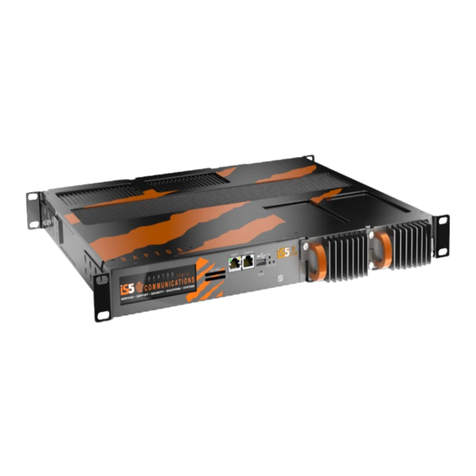
IS5 COMMUNICATIONS RAPTOR Series User manual

USER GUIDE
C O M M U N I C A T I O N S
SERVICES • SUPPORT • SECURITY • SOLUTIONS • SYSTEMS
SERIES
Rev 1.3.6, Apr 2020
Hardware Installation Guide

COPYRIGHT NOTICE
© 2020 iS5 Communications Inc. All rights reserved.
No part of this publication may be reproduced in any form without the prior written consent of iS5 Communications Inc.
(iS5).
TRADEMARKS
iS5Com is a registered trademark of iS5. All other trademarks belong to their respective owners.
REGULATORY COMPLIANCE STATEMENT
Product(s) associated with this publication complies/comply with all applicable regulations. For more details, refer to the
Technical Specications section.
WARRANTY
iS5 warrants that all products are free from defects in material and workmanship for a specied warranty period from
the invoice date (5 years for most products). iS5 will repair or replace products found to be defective within this warranty
period including shipping costs. This warranty does not cover product modications or repairs done by persons other than
iS5 approved personnel, and this warranty does not apply to products that are misused, abused, improperly installed, or
damaged by accident.
Refer to the Technical Specications section for the actual warranty period(s) of the product(s) associated with this
publication.
DISCLAIMER
Information in this publication is intended to be accurate. iS5 shall not be responsible for its use or infringements on third
parties because of the use of this publication. There may occasionally be unintentional errors on this publication. iS5
reserves the right to revise the contents of this publication without notice.
CONTACT INFORMATION
iS5 Communications Inc.
5895 Ambler Drive, Mississauga, On, L4W 5B7
Tel: + 905-670-0004 // Fax: + 289-401-5206
Website: www.iS5Com.com
Technical Support
E-mail: [email protected]
Sales Contact

CONTENTS
1. Introduction . . . . . . . . . . . . . . . . . . . . . . . . .1
1.1 Key Features and Benets of Raptor . . . . . . . . . . . . . . . 1
2. Features of Raptor . . . . . . . . . . . . . . . . . . . . .2
2.1 Line Modules . . . . . . . . . . . . . . . . . . . . . . . . . . . . 2
2.1.1 List of Line Modules . . . . . . . . . . . . . . . . . . . . . . . . . . . . . . 2
2.1.2 Line Modules Details. . . . . . . . . . . . . . . . . . . . . . . . . . . . . .3
2.1.3 Mechanical Drawing of a Line Module (generic) . . . . . . . . . . . . . . . 4
2.2 Power Supply Modules . . . . . . . . . . . . . . . . . . . . . . . 4
2.2.1 List of Power Supply Modules. . . . . . . . . . . . . . . . . . . . . . . . .4
2.2.2 Mechanical Drawing of a Power Supply Module . . . . . . . . . . . . . . .5
2.3 Chassis . . . . . . . . . . . . . . . . . . . . . . . . . . . . . . . 6
3. Raptor Panels Description . . . . . . . . . . . . . . . . .6
3.1 Front Panel Elements . . . . . . . . . . . . . . . . . . . . . . . . 7
3.2 Back Panel Elements . . . . . . . . . . . . . . . . . . . . . . . . 8
3.3 LED Indicators Summary . . . . . . . . . . . . . . . . . . . . . 8
4. Mounting and Installing Raptor . . . . . . . . . . . . . .9
4.1 Prevention of Electrostatic Discharge Damage . . . . . . . . . . 9
4.2 Before Rack Installation . . . . . . . . . . . . . . . . . . . . . . 9
4.3 Unpacking Device . . . . . . . . . . . . . . . . . . . . . . . . . 10
4.4 Prerequisites for Mounting Device on a Rack . . . . . . . . . . 10
4.5 General Procedure for Installing and Starting Raptor . . . . . 10
INSTALLATION GUIDE |
IM-Raptor-1.3.6-EN

4.5.1 Electrical / Mechanical Hazards Prevention . . . . . . . . . . . . . . . . 11
4.5.2 Humidity and Dust Hazards . . . . . . . . . . . . . . . . . . . . . . . . . 11
4.6 Mounting Raptor on a Rack . . . . . . . . . . . . . . . . . . . 11
4.7 Equipment Needed for Raptor's Installation. . . . . . . . . . . 12
5. Modules Installation . . . . . . . . . . . . . . . . . . . 13
5.1 Power Supply Modules Installation . . . . . . . . . . . . . . . 13
5.2 Removal of Power Supply Modules from Chassis . . . . . . . 14
5.3 Line Modules Installation. . . . . . . . . . . . . . . . . . . . . 15
5.4 Removal of Line Modules from Chassis . . . . . . . . . . . . . 16
5.5 iRM-4TGSFP Module Installation . . . . . . . . . . . . . . . . 17
5.6 Removal of iRM-4TGSFP Module . . . . . . . . . . . . . . . . 18
5.7 Inserting SD Card in SD Slot . . . . . . . . . . . . . . . . . . . 19
5.8 Removing SD Card . . . . . . . . . . . . . . . . . . . . . . . . 20
6. Electrical Wiring . . . . . . . . . . . . . . . . . . . . . .20
6.1 Power Inputs and Fault Relay . . . . . . . . . . . . . . . . . . 20
6.2 Connecting AC Power. . . . . . . . . . . . . . . . . . . . . . . 21
6.3 Connecting DC Power. . . . . . . . . . . . . . . . . . . . . . . 22
6.4 Connecting Ground Wire for Safety Precautions . . . . . . . . 23
7. Device Management . . . . . . . . . . . . . . . . . . . 24
7.1 Serial Console . . . . . . . . . . . . . . . . . . . . . . . . . . . 24
7.2 Ethernet Ports & Communication Cabling. . . . . . . . . . . . 24
7.3 RJ45 Ethernet Pinouts . . . . . . . . . . . . . . . . . . . . . . 24
7.4 Recommendations for Cables in High Electrical Noise. . . . . 26
IM-Raptor-1.3.6-EN
| Table of Contents

7.5 SFP. . . . . . . . . . . . . . . . . . . . . . . . . . . . . . . . . 26
7.5.1 Mechanical Dimensions of a SFP module . . . . . . . . . . . . . . . . . 27
7.5.2 Differences between SM and MM Fibers . . . . . . . . . . . . . . . . . . 28
7.5.3 General Fiber Optic Cables Handling Instructions . . . . . . . . . . . . . 28
8. TECHNICAL SPECIFICATION . . . . . . . . . . . . . . . 29
9. COMPLIANCE SPECIFICATION . . . . . . . . . . . . . . 29
INSTALLATION GUIDE |
IM-Raptor-1.3.6-EN

INSTALLATION GUIDE |
IM-Raptor-1.3.6-EN
Preface
This guide is intended for use of network technical support skilled persons who are responsible for installation,
commissioning, and maintenance of the device.
Alerts
WARNING alerts describe hazardous situations that, if not avoided, may result in serious injury and/or
equipment damage.
CAUTION alerts describe hazardous situations that, if not avoided, may result in equipment damage.
DANGER alerts describe imminently hazardous situations that, if not avoided, will result in death or serious
injury.
NOTES provide additional information and details.
Temperature hazard – above TS2 limits. To be accessible by Skilled Persons only
Multiple power source - redundant power
Protective earthing conductor
Electrical hazard – above ES2 limits. To be accessible by Skilled Persons only

IM-Raptor-1.3.6-EN
Related Documents
1. Raptor Quick Start Guide
2. Raptor WebUI Manuals
3. Raptor CLI User Manuals
4. Raptor Conguration Manuals
Training
Training is a key for customers to continue maintaining and using their iS5Com's device.
Customers can select a standard training course or customized training courses at the iS5Com facility or a customer
provided facility.
Go to https://is5com.com/training/ to submit your request for training or contact an iS5Com Sales Representative.

INSTALLATION GUIDE |
IM-Raptor-1.3.6-EN
iSUPPORT
PHONE SUPPORT
Support can be directed to iS5Com’s Technical Action Center at support@ iS5Com.com.
You can also call our Tech Support: +1 844-475-8324
SERVICE LEVEL AGREEMENTS
Service Level Agreements can be tailored to suit your needs with our standard Service Level Agreement packages or
through customized solutions.
RETURN MANUFACTURING AUTHORIZATION
Return Manufacturing Authorization is easy and simplied for our customers. Contact the support team at support@
iS5Com.com or call us to complete and submit your repair or replacement request through our Technical Action Centre.

1| Introduction
IM-Raptor-1.3.6-EN
1. Introduction
Raptor® is an Intelligent Cyber Secure Platform running the iBiome OS. The iBiome is an all-encompassing operating
system that supports switching and routing on a single platform. Raptor has been designed for future scalability. Its
modular system of eld replaceable line blocks, hot swappable power supplies, and its ability to run third party software
applications makes it a very flexible platform for today and the future.
1.1 Key Features and Benets of Raptor
FEATURES BENEFITS
SINGLE PLATFORM FUNCTION The multi-service platform allows the user to connect various plug-in modules to meet their func-
tional requirements
SIMPLIFIED GUI - EASY TO USE
Allows easy conguration and monitoring with a web-based User Interface
Eliminates the need for more complex terminal emulation programs
Reduced cost of deployment; one platform—multiple functions
Built-in LCD display provides easy access to information
ROBUST INDUSTRIAL DESIGN -40 °C to +85 °C (-40 °F to 185 °F) operating temperature, no fans needed
IP 40

INSTALLATION GUIDE | 2
IM-Raptor-1.3.6-EN
2. Features of Raptor
2.1 Line Modules
2.1.1 List of Line Modules
PART # SLOTS 1 - 3 LINE MODULES DESCRIPTION
BLK Blank Module
8GRJ45 8 X 10/100/1000Base-T(X) RJ45
8GSFP 8 X 100/1000Base-X SFP (optical transceivers not included)
PART # SLOT 4 LINE MODULES DESCRIPTION
BLK Blank Module
4TGSFP 4 X 1G/10GBase-X SFP (optical transceivers not included)
PART # DESCRIPTION NOMINAL RANGE OPERATING RANGE
LV Low Voltage Power Module 24 VDC 10-36 VDC
MV Medium Voltage Power Module 48 VDC 36-76 VDC
HV High Voltage Power Module 100-240 VAC, 50/60 Hz
100-240 VDC
85-264 VAC
88-300 VDC

3| Features of Raptor
IM-Raptor-1.3.6-EN
2.1.2 Line Modules Details
The line modules (LM) are as shown below:
LINE MODULE DESCRIPTION
iRM-8GRJ45 - 8 X 10/100/1000 BASE -T(X) RJ45
(to be used in Slots 1, 2, and 3)
iRM-8GSFP - 8 x 100/1000Base-X SFP
(to be used in Slots 1, 2, and 3)
iRM-4TGSFP - 4 x 1G/10GBase-X SFP

INSTALLATION GUIDE | 4
IM-Raptor-1.3.6-EN
2.1.3 Mechanical Drawing of a Line Module (generic)
All dimensions are shown in inches.
2.2 Power Supply Modules
2.2.1 List of Power Supply Modules
POWER SUPPLY MODULE DESCRIPTION
LV Low Voltage Power Module
24 VDC Nominal, 10-36 VDC Operating
MV Medium Voltage Power Module
48 VDC Nominal, 36-76V DC Operating
HV
High Voltage Power Module
Nominal Voltage:
100-240 VAC, 50/60 Hz
100-240 VDC
Operating Voltage:
85-264 VAC /
88-300 VDC

5| Features of Raptor
IM-Raptor-1.3.6-EN
2.2.2 Mechanical Drawing of a Power Supply Module
All power supply (PS) modules (LV, MV, and HV) have the same dimensions as shown above.
All dimensions are shown in inches.

INSTALLATION GUIDE | 6
IM-Raptor-1.3.6-EN
2.3 Chassis
All dimensions are shown in inches (millimeters).
3. Raptor Panels Description
This section contains views of the front and back panels of the Raptor. The locations of the power modules, interface
module slots, and status indicators are shown.
Raptor supports the following slot types:
♦Slot #1- 3 with up to 8 x 10/100/1000 RJ45s or 8 x 100/1000 SFPs
♦Slot #4 with up to 4 x 10GB Base-X or 4 x 1 GB Base-X uplinks
The product label is located at the bottom of the unit.

7| Raptor Panels Description
IM-Raptor-1.3.6-EN
3.1 Front Panel Elements
SD cover elements (a sample is shown on right) can vary.
1. SD Card
A SD Card port may be used to store syslogs. SD#1 (top) is disabled by default. SD slot #2 (bottom) is available for
customer use.
2. Management Port
This 10/100Base-T Ethernet port is used as an out-of-band factory service port. It is disabled by default and not available
for user access.
3. RS232 Serial Console Port
This port is for interfacing directly with the device and accessing management functions via serial interface.
4. USB Port
The USB port can be used to upgrade or back up the Raptor's software or conguration les.
5. Power Status LEDs
The light-emitting diodes (LED)s indicate the status of the power supply modules.
6 & 7 Power Supplies 1 and 2
Two power supplies may be used for redundancy.

INSTALLATION GUIDE | 8
IM-Raptor-1.3.6-EN
3.2 Back Panel Elements
Line Module 3 is located underneath line module 4 and is not shown.
3.3 LED Indicators Summary
TYPE DESCRIPTION STATUS
PS1 Power Status LED 1 Green: OK
No light: No power module installed
PS2 Power Status LED 2 Green: OK
No light: No power module installed
Alarm Alarm Indicator LED
Indicates when an alarm condition exists.
Green: Alarms cleared / acknowledged
Red: Alarm is on
All port status LEDs are as shown on LED display (see below).

9| Mounting and Installing Raptor
IM-Raptor-1.3.6-EN
4. Mounting and Installing Raptor
The Raptor is designed for maximum mounting and display flexibility. It can be equipped with brackets that allow installation
in a 48 cm (19 in) rack.
4.1 Prevention of Electrostatic Discharge Damage
The device components are prone to electrostatic discharge (ESD) damage. ESD damage, which can cause intermittent
or complete component failures, can occur by voltages as low as 30 V. Potentially destructive static voltages can happen
during handling of plastic or foam packing material or when moving components across plastic or carpets.
Some guidelines to minimize the potential for ESD damage are:
♦Always use an ESD wrist strap when you are working with components that are subject to ESD damage, and make sure
that ESD wrist strap is in direct contact with your skin.
♦If a grounding strap is not available, then to ground yourself, touch the exposed bare metal of the device with the other
hand immediately before inserting the component into the device.
To ensure protection by the ESD strap, periodically check its resistance value.
The measured value must be in the range between 1 and 10 MΩ.
♦When handling any component that is subject to ESD damage and is to be removed from the device, make sure the
equipment end of your ESD wrist strap is attached to the ESD point on the chassis.
♦Avoid contact between the component that is subject to ESD damage and clothing. ESD voltages emitted from fabric
can damage components.
♦When removing or installing a component that is subject to ESD damage, always place its components upside on an
antistatic surface, in an antistatic card rack, or in an antistatic bag. If you are returning a component, place it in an
antistatic bag before packing it.
4.2 Before Rack Installation
♦Ensure that you understand how to prevent ESD damage.
♦Place the rack in its permanent location, allowing adequate clearance for airflow and maintenance, and secure it to the
structure.
♦Remove the switch from the shipping package (see Sec 4.3 Unpacking Device).
♦Ensure that you have all necessary parts and tools needed to mount the switch on the rack.
Do not plan to use the device in a location where children are likely to be present.

INSTALLATION GUIDE | 10
IM-Raptor-1.3.6-EN
4.3 Unpacking Device
♦Inspect the package for damage before opening.
♦Open the package and visually inspect all items for issues.
♦Conrm that all items are available.
If there any missing or damaged items, contact iS5Com Support.
4.4 Prerequisites for Mounting Device on a Rack
Heat generated by the device is channeled outwards from the enclosure. For improved convectional airflow,
make sure that there is at least one rack-unit of space or 44 mm (1.75 in) of space around all sides of the
device or between the devices on the rack.
Forced airflow is not required. However, any increase in airflow will result in a reduction of ambient temperature
and improve the long term reliability of the equipment mounted in the rack space.
4.5 General Procedure for Installing and Starting Raptor
♦Review the Compliance Specication (see section 10) for any regulatory requirements.
♦Mount the device.
♦Connect the failsafe alarm relay.
♦Connect power to the device and ground the device.
♦Connect the device to the network.
♦Congure the device.
This equipment is intended only for use in a restricted access area.

11 | Mounting and Installing Raptor
IM-Raptor-1.3.6-EN
4.5.1 Electrical / Mechanical Hazards Prevention
♦When installing the device in a closed or multi-device rack, be aware that the operating ambient temperature of the rack
may be higher than the ambient temperature of the room. Make sure the rack is installed in a suitable environment that
can withstand the maximum ambient temperature generated by the rack.
♦Do not exceed the maximum number of devices or weight restrictions specied by the rack manufacturer.
♦Do not overload the supply circuit. Refer to the overcurrent protection and power supply ratings specied by the rack
manufacturer.
♦Make sure the rack and all devices have a proper ground-to-Earth connection. Pay particular attention to power supply
connections other than direct connections to the branch circuit (e.g. power strips). Ensure that the rack mount adapters
are installed on the correct side of the chassis.
Electrocution hazard – risk of death, serious personal injury and/or damage to the device.
Caution – Access to wiring terminals and replaceable modules is restricted to Skilled Persons only.
4.5.2 Humidity and Dust Hazards
Do not store the switch in locations where it will be subject excessive dirt and dust and high humidity. Conformal coating
is recommended for humid / moist applications.
4.6 Mounting Raptor on a Rack
Ensure that the rack mount brackets are installed on the correct side of the chassis.
1. Raptor Unit
2. Mounting Bracket
3. Mounting Screws

INSTALLATION GUIDE | 12
IM-Raptor-1.3.6-EN
To secure the device to a standard 48 cm (19 in) rack, perform the following:
Step 1: Install the mounting brackets to Raptor using 4 x M4 x 0.7 screws on each side (screws will be provided with the
switch). Use minimum of 2 brackets (4 brackets are included). Brackets are to be adjusted based on rack dimensions.
Step 2: Place the switch in the rack by tilting the switch at an angle so that the ears will clear the mounting rails. Mount it
on the rack using rack screws at the front and rear brackets.
4.7 Equipment Needed for Raptor's Installation
PART # DESCRIPTION QTY
1 Mounting screw M 4 x 0.7 16 (included)
2 Mounting bracket 4 (included)
3Screwdriver 1 (not included)
Other manuals for RAPTOR Series
1
Table of contents
Other IS5 COMMUNICATIONS Control Unit manuals
Popular Control Unit manuals by other brands

Task Force Tips
Task Force Tips Pressure Relief Valve INSTRUCTIONS FOR SAFE OPERATION AND MAINTENANCE

Goetze
Goetze 851 Assembly and maintenance instructions

LG Innotek
LG Innotek TWFM-B006D user manual

Johnson Controls
Johnson Controls Digital Vision Network 5000 Series Upgrade instructions

Omegon
Omegon MiniTrack LX2 instruction manual

SIMARINE
SIMARINE SCQ25T user manual