EVC electronic OLS300 User manual

Manual for the
Online Simulator
Module
OLS300

CONTENTS
1INTERFACE ............................................................................................................................................... 3
2FRONT PANEL .......................................................................................................................................... 3
3POWER SUPPLY....................................................................................................................................... 4
3.1 POWER JACK...................................................................................................................................... 4
3.2 DISPLAY OF THE CHARGING CONDITION.................................................................................. 4
4CONNECTING TO THE ECU ................................................................................................................. 5
5WHAT YOU SHOULD CONSIDER ABSOLUTELY ............................................................................ 6
6EPROM TYPES AND PROPER ADAPTERS ........................................................................................ 7
6.1 ORIENTATION OF PIN1 OF THE OLS ADAPTER CABLES............................................................................. 8
7SPECIAL PARTS 87BC6QG / CC460...................................................................................................... 9
7.1 87BC6QG ............................................................................................................................................. 9
7.2 CC460 ................................................................................................................................................. 10
8TECHNICAL SPECIFICATIONS.......................................................................................................... 11
EVC electronic GmbH 2 Manual OLS300
EVC electronic GmbH
Am Pfauenzehnt 11a
D-46539 Dinslaken
Tel.: +49(2064)4163-0
Fax.: +49(2064)4163-33
Program updates as well as an overview of our products are available on the internet at:
www.evc.de

1 INTERFACE
The simulator module has to be connected to the USB- port of your com-
puter.
This port should according the USB conventions describing the USB-
Version USB 1.x (full speed/ 12Mb/s).
It also provides the OLS300 moduls power supply.
2 FRONT PANEL
The front panel insists of the following parts:
Ignition- / configuration
indicator. This LED flas-
hes slowly, as soon as the
simulator configuration was
loaded (ca.1Hz). The LED
flashes rapidly, if the igni-
tion is switched on
(approx. 3Hz).
The PWR/BAT- LED be-
gins flashing, as soon as the
device has finished power-
up and initialising sequence
The OLS300 is now expect-
ing to load the configura-
tion data via USB- interface
External DC socket ac-
cording DIN 2514, used
for fast charging the Li-
ion battery. This socket
is protectet against
wrong polarity connec-
tion
The USB type B socket
has to be connected to
your notebook or PC. If
the notebook or the PC
is swiched on, the Li-ion
battery of the OLS300
will be charged
EVC electronic GmbH 3 Manual OLS300

3 POWER SUPPLY
The power supply of the OLS300 module is provided by a rechargeable li-
ion battery having a capacity of 1700 mAh. This type of battery is mainte-
nance-free, nearly age resistant and free of the so called “memory effect”.
This effect caused rechargeable batteries of former generations to reduce the
number of possible charging cycles.
Normaly, the li-ion battery is charged by the USB-Power while the OLS300
module is connected to a switched-on USB host (notebook or PC) . Doing
so, a discharged li-ion battery will be totally charged within approx. 8 hours.
Depending on the temperature of the enviroment, the li-ion battery is able to
supply the configured OLS300 module with power for 8 to 14 hours.
The li-ion battery of the OLS300 module cannot be overcharged. Permanet
charging doesn't matter. Over- discharging the Li- ion battery is also not
possible, because an integrated protection circuit will restrain this. When the
Li-ion battery is discharged to its minimum, the protection circuit will
switch-off the OLS300 module, no matter the position of the power switch.
You can simply ‘reactivate’ the OLS300 module by connecting it to a
switched-on PC or Notebook via USB-cable.
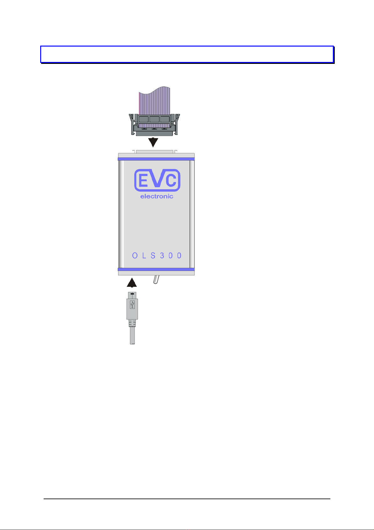
3.1 POWER JACK
Considering the case, it becomes necessary to charge the Li-ion battery in
the fast charge mode, you can use the DC socket on the front panel, which is
according to DIN 2514. A commercial low voltage power supply with an
output voltage between 9Vand 24V can be used. Acting so, a discharged Li-
ion battery will totally charged within approx. 1.5 hours.
3.2 DISPLAY OF THE CHARGING CONDITION
The PWR/BAT- LED shows the battery condition by its lighting duration:
Long lighting means full-condition, short lighting shows nearly-empty-
condition.
You can observe the actual battery charging condition exactly when moving
the mouse cursor onto the battery symbol in the status line of the WinOLS
program.
EVC electronic GmbH 4 Manual OLS300

4 CONNECTING TO THE ECU
• The matching adapter cable has
to be plugged into the IC socket
instead of the EPROM. Eventu-
ally a socket has to be soldered
into here first. In this case, you
must not ignore the location of
Pin1.
• In case of an incorrectly applied
cable, e.g. the Pin1 is on the
wrong side or the cable is
pluged lengthwise shifted, the
destruction of the control unit
and/ or the simulator module
may be possible.
• The next step is to connect the
adapter cable to the simulator
module.
• The EPROM contents are load-
ing down to the module when
the configuration file was
loaded down automatically first.
• ! Not earlier but now the igni-
tion controls may be trig-
gered!
• If the OLS300 is configured, the
blue IGN/CFG- LED indicates
the triggered ingnition controls
with flashing rapidly.
EVC electronic GmbH 5 Manual OLS300

5 WHAT YOU SHOULD CONSIDER ABSOLUTELY
SWITCHING ON THE IGNITION WITHOUT
PREVIOUS LOADED CONFIGURATION MAY
DESTROY THE SIMULATOR MODULE !
This is absolutly necessary, because the loading of the configuration
file into the OLS300 simulator module determines which wires will
be defined to work like outputs and/ or inputs. Without loading the
correct configuration file (considering control unit, EPROM-type
etc.), the control unit and/ or the simulator modul may be damaged.
NEVER CONNECT THE ADAPTER CABLE
WHEN THE IGNITION IS SWITCHED ON !
First make sure, that the adapter cable is plugged in correctly, at the
right position with no disalignemt and the GND- Pin(s) are con-
nected well. You must not switch on the ingnition earlier!
NEVER DISCONNECT THE ADAPTER CABLE
BEFORE THE IGNITION IS SWITCHED OFF !
Before picking up the adapter cable from the control unit, make sure
that the ignition is switched off !
AVOID TO EXPOSE THE SIMULATOR MOD-
ULE EXTREMLY HIGH TEMPERATURES!
In the engine compartment, try to place the OLS300 simulator mo-
dule at the coolest possible place. Never place the simulator module
directly at engine parts wich can become very hot like cylinder
head, exhaust pipe, etc..!
WATCH THE GROUND CABLES!
Make sure, that all of the involved conponent are well connected to
ground. Never reconnect the assembly during simulation! (e.g. by
connecting the notebook to the zigarette lighter receptable sourced
notebook power supply while the assembly is runnig).
EVC electronic GmbH 6 Manual OLS300

6 EPROM TYPES AND PROPER ADAPTERS
Classification of adapters according to EPROM types:
Adapter OLS328 OLS328 +
EAD101
OLS328 +
EAD100
OLS340 OAD40 +
EAD110*
OLS344
Case
Kbit
DIL28 +
DIL32
PLCC32 PLCC32 DIL40 PLCC44 PSOP44
64 2764
128 27128
256 27C256,
87C257,
28F256
27C256 28F256
512 27C512,
87C510,
27F512
27C512,
87C510
28F512
1024 87C110,
27C1001,
TI27C010,
28F010,
M28F101
87C110 27C1001,
TI27C010,
28F010,
M28F101
27C1024,
M28F102
27C1024,
M28F102
28F100,
29F100,
M28F110,
M28F120
2048 27C2001,
TI27C020,
28F020,
M28F201
27C2001,
TI27C020,
28F020,
M28F201
28F200,
29F200,
M28F210,
M28F220
4096 27C4001,
TI27C040,
28F040,
M28F401,
29F040
27C4001,
TI27C040,
28F040,
M28F401,
29F040P
27C4096,
M28F402
27C4096,
M28F402
28F400,
29F400,
M28F410,
M28F420
8192 AM29F800
Special adapters:
Adapter OLS368
Case
KBit
PLCC68 supported operating modes:
384 87BC6QG all modes
832 CC460 Mode 1 and mode 5
Adapter OLS356*
Gehäuse
KBit
SSOP56 * still under development.
8192 29BL802,
28F800F3
EVC electronic GmbH 7 Manual OLS300

6.1 ORIENTATION OF PIN1 OF THE OLS ADAPTER CABLES
OLS344 OLS328 OLS340
OLS332
OLS368
When using an OLS 332 adapter it is important to be aware of the „low“
and „high“ byte- EPROM.
The OLS368 adapter has a 68-pin PLCC socket where the previously unsol-
dered original chip must be inserted. The simulator only plays the part of the
EPROM of the chip. All the other functions like ports and RAM require the
original chip. Thus the data content of the inserted chip is not relevant
but the configuration of the device.
EVC electronic GmbH 8 Manual OLS300

7 SPECIAL PARTS 87BC6QG / CC460
When modifying the combination modules 87BC6QG ( 87M12 ) and CC460
a few special properties have to be taken into account. Besides the port func-
tions and RAM the 87BC6QG contains a 48 Kbyte UV erasable EPROM
and the CC460 a 96 Kbyte sized flash EPROM.
Especially the CC460‘s flash EPROM is not arranged in one piece but in
several blocks, thus the lookup tables are following for reasons of compati-
bility:
7.1 87BC6QG
As mentioned above, this module contains an UV erasable EPROM, while
the usual variant within a plastic case doesn’t have a window, of course, thus
it is OTP (one time programmable).
Now, this module features two additional registers, which are LR and CSR.
In a HEX window they are displayed at the addresses of 10000h and 10001h.
These addresses shouldn’t be modified while editing because hereby the
memory layout is being switched. When reading out and reprogramming as
well as at simulations these data will be transferred automatically, too.
These memory blocks are being displayed at the proper address, too, while
the rest is being shown as FF and cannot be programmed.
When working with the simulator the configuration is being loaded auto-
matically. The simulator adapter’s ZIF (zero insertion force) socket has to
contain a 87BC6QG with the same configuration while the data it contains is
irrelevant.
Configuration 0, 1 2, 3 4, 5 6, 7
EPROM 4000 – FFFF 2000 – DFFF 0000 - BFFF 4000 - FFFF
EVC electronic GmbH 9 Manual OLS300

7.2 CC460
The CC460‘s advantage lies at the flash memory, of course, which is delete-
able and reprogrammable.
Here the configuration register is called CSR and is located at 1FFFF.
In addition to the fact that a version 1 and a version 2 exists the first version
contains 4 and the second one 5 configurations. Nearly all control units
which contain this module are using version 2 / configuration 1. In the near
past several control units ( Citroen, Peugeot, Renault ) appeared on the mar-
ket which use configuration 5.
The OLS system only supports the configurations 1 and 5 at this time. Be-
sides that the EPROMmer is able to program the CSR but it cannot erase it.
Here the simulator adapter’s ZIF socket also has to contain a module with
the same configuration and the data contents are irrelevant, too.
Configuration 1 5
EPROM1 00000 – 01FFF 00000 – 01FFF
EPROM3A 04000 – 07FFF 06000 – 07FFF
EPROM2 08000 – 0BFFF 0C000 – 0FFFF
EPROM3B 10000 – 13FFF 10000 – 13FFF
EPROM3C 14000 – 17FFF 14000 – 17FFF
EPROM3D 18000 – 1BFFF 18000 – 1BFFF
EPROM3E 08000 – 0FFFF 1C000 – 1FFFD
EPROM3F - 08000 – 09FFF
EVC electronic GmbH 10 Manual OLS300

EVC electronic GmbH 11 Manual OLS300
8 TECHNICAL SPECIFICATIONS
Interface USB 1.x Full- Speed
min. (12Mb/s)
Simulation memory 4 MByte
Power supply 1.7Ah Li-Ion polymere
rechargeable battery
Dimensions (W x H x D) 85 x 35 x 141 mm
(31/2x 13/8x 51/2Inch)
Weight 280 g (9.88 oz.)
Table of contents
Other EVC electronic Control Unit manuals