manuals.online logo
Brands
  1. Home
  2. •
  3. Brands
  4. •
  5. IS5 COMMUNICATIONS
  6. •
  7. Media Converter
  8. •
  9. IS5 COMMUNICATIONS iPS2 User manual

IS5 COMMUNICATIONS iPS2 User manual

Other IS5 COMMUNICATIONS Media Converter manuals

IS5 COMMUNICATIONS iPS2 User manual

IS5 COMMUNICATIONS

IS5 COMMUNICATIONS iPS2 User manual

IS5 COMMUNICATIONS iSC2 Series User manual

IS5 COMMUNICATIONS

IS5 COMMUNICATIONS iSC2 Series User manual

IS5 COMMUNICATIONS iPS2 User manual

IS5 COMMUNICATIONS

IS5 COMMUNICATIONS iPS2 User manual

IS5 COMMUNICATIONS iSC2F User manual

IS5 COMMUNICATIONS

IS5 COMMUNICATIONS iSC2F User manual

Popular Media Converter manuals by other brands

TR-Electronic CMS582M-4096/4096 IOL DMS 14H7 KRF Assembly instructions

TR-Electronic

TR-Electronic CMS582M-4096/4096 IOL DMS 14H7 KRF Assembly instructions

Korenix JetCon 2301S user manual

Korenix

Korenix JetCon 2301S user manual

StarTech.com ET91000LCOAM manual

StarTech.com

StarTech.com ET91000LCOAM manual

Alesis AI-3 Reference manual

Alesis

Alesis AI-3 Reference manual

Caton Vpro 5100 user guide

Caton

Caton Vpro 5100 user guide

Cypress CSC-5500 Operation manual

Cypress

Cypress CSC-5500 Operation manual

H&B TX-100 Installation and instruction manual

H&B

H&B TX-100 Installation and instruction manual

Bolin Technology D Series user manual

Bolin Technology

Bolin Technology D Series user manual

IFM Electronic Efector 400 RN30 Series Device manual

IFM Electronic

IFM Electronic Efector 400 RN30 Series Device manual

GRASS VALLEY KUDOSPRO ULC2000 user manual

GRASS VALLEY

GRASS VALLEY KUDOSPRO ULC2000 user manual

Linear Technology DC1523A Demo Manual

Linear Technology

Linear Technology DC1523A Demo Manual

Lika ROTAPULS I28 Series quick start guide

Lika

Lika ROTAPULS I28 Series quick start guide

Weidmuller IE-MC-VL Series Hardware installation guide

Weidmuller

Weidmuller IE-MC-VL Series Hardware installation guide

Optical Systems Design OSD2139 Series Operator's manual

Optical Systems Design

Optical Systems Design OSD2139 Series Operator's manual

Tema Telecomunicazioni AD615/S product manual

Tema Telecomunicazioni

Tema Telecomunicazioni AD615/S product manual

KTI Networks KGC-352 Series installation guide

KTI Networks

KTI Networks KGC-352 Series installation guide

Gira 0588 Series operating instructions

Gira

Gira 0588 Series operating instructions

Lika SFA-5000-FD user guide

Lika

Lika SFA-5000-FD user guide

manuals.online logo
manuals.online logoBrands
  • About & Mission
  • Contact us
  • Privacy Policy
  • Terms and Conditions

Copyright 2025 Manuals.Online. All Rights Reserved.

RJ-45Input (Data and Power) RJ-45Output (DataOnly)
Symbol Description Symbol Description
1
BI_DA+
DataBI_DA+
BI_DA+
Data BI_DA+
2BI_DA-DataBI_DA-BI_DA-Data BI_DA-
3
BI_DB+
DataBI_DB+
BI_DB+
Data BI_DB+
4BI_DC+ (Vdc+) Data BI_DC+ andFeedingpower(+) BI_DC+ Data BI_DC+
5BI_DC- (Vdc+)DataBI_DC- andFeeding power(+) BI_DC-Data BI_DC-
6BI_DB-DataBI_DB-BI_DB-Data BI_DB-
7BI_DD+ (Vdc-) DataBI_DD+ and Feeding power(-) BI_DD+ Data BI_DD+
8BI_DD- (Vdc-) DataBI_DD- andFeeding power(-) BI_DD-Data BI_DD-
RJ-45Output (Data and Power) RJ-45Output (DataOnly)
Symbol Description Symbol Description
1Rx+ Data Receive Rx+ DataReceive
2
Rx-
DataReceive
Rx-
DataReceive
3
Tx+
DataTransmit
Tx+
DataTransmit
4Vdc+ Feedingpower(+)
NC NotConnected
5Vdc+ Feedingpower(+)
NC NotConnected
6
Tx-
DataTransmit
Tx-
DataTransmit
7Vdc-Feedingpower(-) NC NotConnected
8Vdc-Feedingpower(-) NC NotConnected
RJ-45Input (Data and Power)
RJ-45Output (DataOnly)
Symbol Description Symbol Description
1
BI_DA+ (Vdc+)
Data BI_DA+ and Feedingpower(+)
BI_DA+
Data BI_DA+
2
BI_DA- (Vdc+)
Data BI_DA- and Feeding power(+)
BI_DA-
Data BI_DA-
3
BI_DB+ (Vdc-)
Data BI_DB+ and Feedingpower(-)
BI_DB+
Data BI_DB+
4BI_DC+ DataBI_DC+ BI_DC+ Data BI_DC+
5BI_DC-DataBI_DC-BI_DC- Data BI_DC-
6BI_DB- (Vdc-) Data BI_DB- and Feeding power(-) BI_DB-Data BI_DB-
7BI_DD+ DataBI_DD+ BI_DD+ Data BI_DD+
8BI_DD-DataBI_DD-BI_DD-Data BI_DD-
RJ-45Input (Data and Power)
RJ-45Output (DataOnly)
Symbol Description Symbol Description
1Rx+ (Vdc+) Data Receive and Feeding power(+) Rx+ Data Receive
2Rx- (Vdc+) Data Receive and Feeding power(+) Rx-DataReceive
3
Tx+(Vdc-)
DataTransmit and Feeding power(-)
Tx+
DataTransmit
4NC NotConnected NC NotConnected
5NC NotConnected NC NotConnected
6
Tx-(Vdc-)
DataTransmit and Feeding power(-)
Tx-
DataTransmit
7NC NotConnected NC NotConnected
8NC NotConnected NC NotConnected
Quick Start Guide
iPS2
–
Industrial Gigabit PoE Splitter
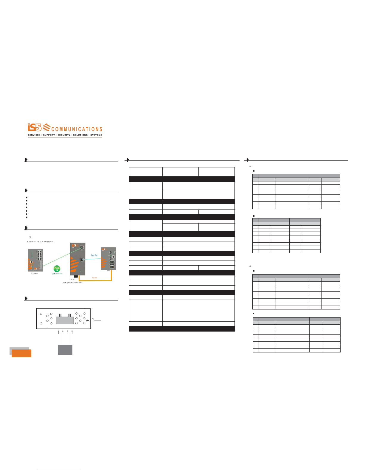
Introduction Specifications Connector and Pin Definition
The iPS2 is a high power PoE Splitter for use in Power over Ethernet systems. With
Ethernet Input (data + power) port and Output (data only) port, the iPS2 may split
power from existing LAN cable and convert up to 24VDC/1.25A for power hungry
applications such as Wireless APs, Security cameras and IP Phones. The internal
current limit, short-circuit and overload protection are implemented for use as a DC
power supply.
iPS2 Model Physical
Ports
10/100/1000 Base-T(X)Ports
PoE Definition 1
1000Base-T
Features
Fully compliant with IEEE802.3at/af standard
Supports 10/100/1000Base-T(X) for PoE In and Data Out
Power Isolation and Short Circuit Protection for Power Output
Auto protection for Over Voltage Power Input
Supports Power Outputs up to 30Watts
in RJ45 Auto MDI/MDIX
1
10/100/1000Base-T(X) P.S.E.
Port in RJ45 Auto MDI/MDIX
1
Operating Voltage
Input Voltage 36 ~ 57 VDC on RJ45 connector
IP-40 Galvanized Steel Case Design
DIN-Rail and wall-mount enabled
Output Power 24V @ 1.25A max. (30 Watts)
LED indicators
PWR / Ready: 1 x LED
24V @ 0.45A max. (10.8 Watts)
10/100 Base-T(X)
Connections
Power indicator
Blue On: Power is on and
functioning Normally.
Green On: Power is on and
functioning Normally.
Connections of Splitter
Protection
Short Circuit Protection
Present
Over Load Protection
Present
Isolation Protection 1500V
Physical Characteristic
Enclosure
IP-40
Note: pins 7 and 8 (-Vdc) should not be shorted to ground
Dimension (W x D x H) 26.1(W) x 70(D) x 95(H)mm (1.03x 2.76 x 3.74inch.)
PoE Definition 2
Weight (g)
Environmental
StorageTemperature
250 g
-40 to 80
o
C (-40 to 176
o
F)
200 g
1000Base-T
OperatingTemperature
-40 to 85
o
C (-40 to 158
o
F)
OperatingHumidity
5% to 90% Non-condensing
Power Connection Guide
G
Frame Ground
Regulatory Approvals
EMI
EMS
Safety
FCC Part 15, CISPR (EN55022) class A
EN61000-4-2 (ESD),
EN61000-4-3 (RS),
EN61000-4-4 (EFT),
EN61000-4-5 (Surge),
EN61000-
4-6 (CS),
EN61000-4-8,
EN61000-4-
11
EN60950-1
10/100 Base-T(X)
V- V- V+ V+ OUT PUT DC 24V
Warranty
5
years
Power
Output
24 VDC
Note: pins 3 and 6 (-Vdc) should not be shorted to ground
QSG
1
8
1
8
1
8
1
8
Quick Start Guide
iPS2
–
Industrial Gigabit PoE Splitter
Installation
Din-Rail Install Step Wall-mounted Install Step
Accessories Communication Connections
1 4-Pin Terminal block 2 Dust Cover (RJ-45) 3 Screw (M3 X3)
1000Base-T Ethernet Port Connection
RJ45 (8-pin, MDI) Port Pinouts RJ45 (8-pin, MDI-X) Port Pinouts
Pin
1
2
3
4
5
6
7
8
MDI
BI_DA+
BI_DA-
BI_DB+
BI_DC+
BI_DC-
BI_DB-
BI_DD+
BI_DD-
PPi
n
1
2
3
4
5
6
7
8
MDI-X
BI_DB+
BI_DB-
BI_DA+
BI_DD+
BI_DD-
BI_DA-
BI_DC+
BI_DC-
4 Wall-mounted kit 5 25mm DIN-Rail kit
10/100Base-T(X) Ethernet Port Connection
RJ45 (8-pin, MDI) Port Pinouts RJ45 (8-pin, MDI-X) Port Pinouts
Pin
Single
Pin Single
1
Tx+
2
Tx-
3
Rx+
6 Rx-
1
Rx+
2
Rx-
3
Tx+
6 Tx-
6 QIG
RJ45 (8-pin) to RJ45 (8-Pin) Straight-Through Cable Wiring
Switch Port
Straight-Through Cable NIC Port
RJ-45
Connector
Tx+
Tx-
Rx+
Rx-
RJ45 Plug Pin1
3
6
1
2
RJ-45
Connector
3 Rx+
6 Rx-
1 Tx+
2 Tx-
RJ45 (8-pin) to RJ45 (8-Pin) Cross-Over Cable Wiring
Switch Port
(NIC Port)
RJ-45
Connector
Cross-Over Cable
RJ45 Plug Pin1
Switch Port
(NIC Port)
RJ-45
Connector
(Rx+) Tx+ 3 1 Rx+ (Tx+)
(Rx-)
(Tx+)
(Tx-)
Tx- 6
Rx+ 1
Rx- 2
2 Rx-
3
Tx+
6 Tx-
(Tx-)
(Rx+)
(Rx-)
Q I G
#3-7490 Pacific Circle, Mississauga, Ontario, L5T 2A3
Support: 1 (905) 670 - 0004
QSG