ISE WEST 4400 How to use

MODEL 4400 TEMPERATURE CONTROL
10100 Royalton Rd.
Cleveland, OH 44133
(440) 237-3200
(440) 237-1744
http://iseinc.com

Model 4400 Ramp Dwell Control
Short Form Instructions
This document is provided for quick reference in the setting of the various commonly used parameters on the 4400 series controller. It is not
meant to cover all possible options or situations. Some knowledge of the 4400 is assumed. The 4400 site and operator manuals are
provided for items that are not covered here. Parameter settings and program values in this document are for illustration only and do not
relate to a particular application.
ISE can provide additional application specific assistance. We also have other tools available such as the full instrument manuals,
configuration software and full SCADA software that are compatible with this control. Visit our web site at http://iseinc.com or contact us
for additional assistance.
ISE has been providing quality instrumentation and support since 1946.
2

CONTROL STATUS
INDICATORS
AT: Auto Tune
ALM: Indicates status alarm output.
OP1: indicates status of output #1.
OP2: Indicates status of output #2.
MAN:Lit if in manual mode.
EVENT INDICATORS
EV1-EV4: Status of event outputs.
RUN STATUS INDICATORS
RUN: Program running
HLD: Program held.
X60: When on: min:seconds.
MODE INDICATORS
SET: On when control define
mode is entered; Flashes when
viewing parameters in controller
or programmer define modes.
PRG: On when in programmer
define mode.
3

UP/DOWN ARROWS: Raises/Lowers value of displayed parameter.
SCROLL KEY: Displays the next parameter in sequence. Also used to
display the program progress in the message display while the program is
running.
MODE KEY: Cycles between Normal Display, Controller Mode, &
Program Modes. Used during setup or to view parameters when not in setup.
PROGRAM KEY: Selects the desired program (recipe) number.
RUN/HOLD KEY: Pressed once: starts selected program; Pressed while
program is running: Holds program at current time & setpoint; If held in for
approximately 5 seconds will abort currently running program.
4

CONTROL PARAMETERS
To enter this mode:
1) Press UP ARROW &SCROW KEYS at same time. “Unlock” will be displayed in message display.
2) Use ARROW KEYS to display your Lock Code (ISE Lock Code as shipped is 10).
3) After setting appropriate Lock code press SCROLL KEY then MODE KEY to get into controller parameter
mode. Use SCROLL KEY to go from parameter to parameter and ARROW KEYS to change values for the
parameters.
MESSAGE DISPLAY LOWER DISPLAY Notes
Filter 2.0 Adjusts Filter time constant
Offset 0 PV offset
Out 1 Read Only Relative output #1— 0-100 %
Out 2 Read Only Relative output #2— 0-100 % (optional)
P. Band 1 5.0 Prop. Band for output #1
P. Band 2 5.0 Prop. Band for output #2 (optional)
Reset 5.00
Rate 1.15
Overlap 0 (Optional)
Bias 25 Reset Preload
SP High 842 Maximum setpoint for process
SP Low 32 Minimum setpoint for process
Out High 100
Cycle Time l 16 Cycle time output #1
DeAlarml 10 Optional alarms (deviation shown)
ALl Hyst 1 Difference between ON & Off of alarm#1
Loop Alarm OFF
Auto PT OFF
A/M Enab OFF
Lock 10 Caution: Changing this number will change lock code.
CONTROL SETPOINT WHILE NOT RUNNING PROGRAM
To change setting press SCROLL KEY when in ‘normal mode’ (SET & PRG lights are out) and use arrow keys to
adjust value of the setpoint.
5

PROGRAM PARAMETERS (General)
To enter this mode:
1) Press UP ARROW & SCROW KEYS at same time. “Unlock” will be displayed in message display.
2) Use ARROW KEYS to display your lock code (ISE lock code as shipped is 10).
3) After setting appropriate lock code press SCROLL KEY to get into program parameter mode. Press PROG
Button until Program number displays “A”. Use SCROLL KEY to go from parameter to parameter and
ARROW KEYS to change values for the parameters.
GENERAL PARAMETERS FOR ALL PROGRAMS
MESSAGE DISPLAY LOWER DISPLAY Notes
Start on SetP or Proc Defines SP value to use on start of program*
End on SetP or Proc Defines SP value to use on end of program*
Delay 0.00 Delays start time of program by time displayed.
LockProg On or Off Doesn’t allow changes while program is running if on.
Recovery 0 or 1 ‘0’ Aborts program on power outage. “1” continues
Ext. Sel nonE Allows external selection of program,run, etc. (option)
* Start on or End on: SetP starts program from the Setpoint value (SP that is used when not running a program).
Proc starts the program from the current process variable (temperature).
GENERAL PARAMETERS FOR SELECTED PROGRAM
Change program number to the desired program number by pressing PROG. Segment number should be blank.
MESSAGE DISPLAY LOWER DISPLAY Notes
Cycles 1 How many times to run program
AutoHold OFF, H_SP, L_Sp or both Hold program if PV is above, below or both by hold band
HoldBand {doesnt show if Auto hold is off} Band for auto hold in degrees
Hold on {doesnt show if Auto hold is off} Hold on dwells, ramps or both
Pre-x60 Off Determines if program is MMSS or HHMM
Min/Sec or Hrs/Min
6

PROGRAM PARAMETERS (Profile)
To enter this mode:
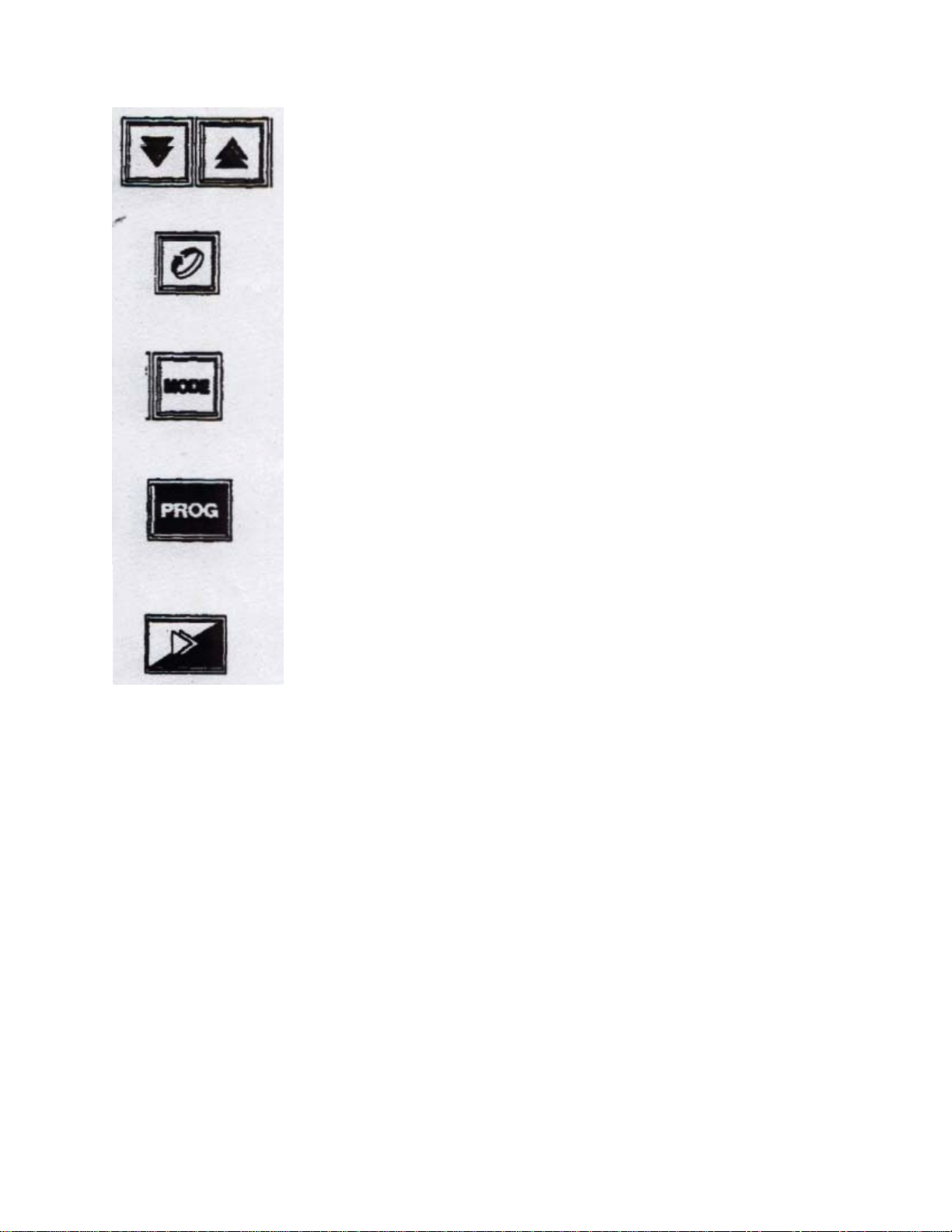
1) Press PROG button until Program number displays the desired program number.
2) Press UP ARROW & SCROLL KEYS at same time. “Unlock” will be displayed in message display.
3) Use ARROW KEYS to display your lock code (ISE lock code as shipped is 10).
4) After setting appropriate lock code press SCROLL KEY. Use SCROLL KEY to go from parameter to
parameter and ARROW KEYS to change values for the parameters.
RAMP/DWELL Sample Program
SEG# MSG DISP. LOWER DISP. NOTES
1 Final SP 400 Ramp to 400
1 Time 1.15 Ramp to 400 in 1 Hour, 15 minutes
1 Event 0101 Turn on optional event #1 & #3
2 FinalSP — Dwell at 400
2 Time 1.20 Dwell for 1 hour 20 minutes
2 Event 0010 Turn off event #1 & 3; turn on #2
3 Final SP 600 Ramp to 600
3 Time 3.00 Ramp from 400 to 600 in 3 hours
3 Event 1000 Turn off event 2; Turn on event #4
4 FIna1SP 800 Ramp to 800
4 Time 0.10 Ramp SP to 800 in 10 minutes
4 Event 0000 Turn off all events
5 Final SP — Dwell Setpoint at 800
5 Time 2.00 Dwelltime=2 Hours at 800
5 Event 0001 Turn on Event #1 (all others off)
6 FIna1SP — Dwell at 800
6 Time 6.00 Dwell at 800 for and additional 6 Hrs
6 Event 0000 turn off events
7 Final SP End End of program
NOTES ON CHANGING PARAMETERS
1) To create a Dwell (—) press RAISE & LOWER BUTTONS at same time.
2) To create an END segment go to “Time” in segment and use DOWN ARROW (past 0.00) until “End” is
displayed in lower display.
3) To create a “Join” to another program: go to “Time” in segment and use DOWN ARROW (past 0.00) until
“J0x” is displayed lower display (where x is the number of the program you went to run at the completion of the
program)
4) The event display is a series of l’s and 0’s signifying that an event is On or Off respectfully. Evt4, Evt3, Evt2, Evtl
is the order on the display. For example :0100 signifies that Event #3 is energized, all others are off.
7

GENERAL INSTRUCTIONS
TO RUN A PROGRAM
1. Apply power to control.
2. Select desired recipe number with PROG BUTTON.
3. Press RUN/HOLD BUTTON.
To Select Manual Control
Press “Scroll” & “Mode” keys at same time. (This mode is normally disabled in the control setup)
To Activate Self Tune
Make sure no programs are running. Press the Scroll key until the message screen shows “SelfTune”. Press the
Mode & the Up Arrow keys at the same time to cycle between on & off for self tune.
To Activate Pre Tune
Make sure no programs are running. Press the Scroll key until the message screen shows “Pre Tune”. Press the
Mode & the Up Arrow keys at the same time to cycle between on & off for pre tune.
WHILE THE PROGRAM IS RUNNING
1. Program number of the currently running program is displayed.
2. Segment number of the current segment is displayed.
3. Arrow(s) are lit to indicate whether Setpoint is ramping up, ramping down or dwelling at a constant temperature.
4. OP1 light illuminates when output #1 is activated.
5. OP2 light (optional) illuminates when output #2 is activated
6. EV1-EV4 light illuminates showing status of optional event relays.
7. Upper display shows temperature (PV).
8. Lower display shows current setpoint.
9. Message display is blank or by pressing SCROLL button displays time remaining in current segment. Also
displays messages to alert the operator of occurrences such as if the program is aborted by someone or due to power
outage.
10. RUN light is illuminated indicating the program is running.
11. HLD light is illuminated if program is being held.
12. Control & Program parameters may be viewed by pressing MODE button and using SCROLL key to step
through the parameters. Normal setup does not allow the operator to change program parameters while the program
is running.
8

TO HOLD A PROGRAM
Holding a program stops the time from advancing. It holds the setpoint at the current value.
To hold the program press and release the RUN/HOLD button. HLD light will illuminate.
To continue with program press and release RUN/HOLD button again. HLD light will go out.
TO ABORT A PROGRAM
Aborting a program stops the program permanently. The setpoint reverts to the programmed setpoint value for when
a program is not running.
To Abort the program press and hold the RUN/HOLD button until Aborted is displayed in message display.
Program can only be restarted from the beginning.
9

Parameter List
Parameter Name Your
Value ISE Default Units
Control Setpoint While
Not Running a Program
(page 5)
Setpoint * Degrees
Control Parameters (page
5)
Filter 2Seconds
Offset 0Degrees
Out1 Read Only%
Out2 Read Only%
P.Band1 5.0%
P.Band2 5.0% Optional
Reset 5.00Min.Sec
Rate 1.15Min.Sec
Diff1 0.1%
Overlap 0%
Bias 25%
Diff1 0.1%
Diff2 0.1% Optional
SP High Scale MaxDegrees
SP Low Scale MinDegrees
Out High 100%
Cycle Time1 16Seconds
Cycle Time2 16Seconds Optional
Alm1 Value Degrees Optional
Alm2 Value Degrees Optional
Auto PT Enab OFF
A/M Enable OFF
Program Number
Program Parameters
(General- Program A)
Page 6
Start on SetP
End on SetP
Delay 0.00Hrs.Mins
Lock Prog On
Recovery 0
Ext Sel nonE Optional
General Parameters
Selected Program Page 6
Cycles 0
Auto Hold OFF
Hold Band 10
Hold On dd=Dwell r= Ramp
Pre X60 OFF
10

Program Parameters
(Profile) page 7
Final Setpoint 1 Degrees
Time Rate 1 Hrs.Min
Event Outputs 1 Binary Value
Final Setpoint 2 Degrees
Time Rate 2 Hrs.Min
Event Outputs 2 Binary Value
Final Setpoint 3 Degrees
Time Rate 3 Hrs.Min
Event Outputs 3 Binary Value
Final Setpoint 4 Degrees
Time Rate 4 Hrs.Min
Event Outputs 4 Binary Value
Final Setpoint 5 Degrees
Time Rate 5 Hrs.Min
Event Outputs 5 Binary Value
Final Setpoint 6 Degrees
Time Rate 6 Hrs.Min
Event Outputs 6 Binary Value
Final Setpoint 7 Degrees
Time Rate 7 Hrs.Min
Event Outputs 7 Binary Value
Final Setpoint 8 Degrees
Time Rate 8 Hrs.Min
Event Outputs 8 Binary Value
Final Setpoint 9 Degrees
Time Rate 9 Hrs.Min
Event Outputs 9 Binary Value
Final Setpoint 10 Degrees
Time Rate 10 Hrs.Min
Event Outputs 10 Binary Value
Final Setpoint 11 Degrees
Time Rate 11 Hrs.Min
Event Outputs 11 Binary Value
Final Setpoint 12 Degrees
Time Rate 12 Hrs.Min
Event Outputs 12 Binary Value
Final Setpoint 13 Degrees
Time Rate 13 Hrs.Min
Event Outputs 13 Binary Value
Final Setpoint 14 Degrees
Time Rate 14 Hrs.Min
Event Outputs 14 Binary Value
Final Setpoint 15 Degrees
Time Rate 15 Hrs.Min
Event Outputs 15 Binary Value
Final Setpoint 16 Degrees
Time Rate 16 Hrs.Min
Event Outputs 16 Binary Value
11
Table of contents
Popular Controllers manuals by other brands

Zapi
Zapi EPS-AC0 user manual

NEC
NEC N8190-171 manual

Schwank
Schwank ThermoControl Plus 4M OPERATING AND INSTALLATION Manual

Mitsubishi
Mitsubishi AD71S1 user manual

Emerson
Emerson DIXELL XD70T Installing and operating instructions

Morningstar
Morningstar REAKSTAR GenStar GS-MPPT-60M-200V Installation, operation and maintenance manual

National Instruments
National Instruments Fieldpoint CFP-2200 Instructions and specifications

StarTech.com
StarTech.com PEXSAT2IDE2 user guide

Vortice
Vortice CNU Instruction booklet

YASKAWA
YASKAWA Varispeed DI-16H2 instructions

IPCOMM
IPCOMM SEC2 General Operating, Maintenance, and Installation Manual

controlair
controlair 400 Installation, operation and maintenance instructions