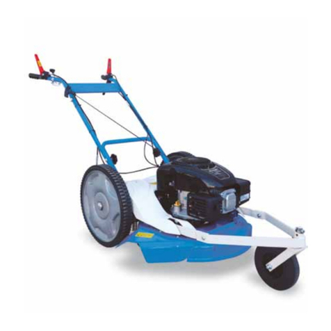
Iseki SRM72 User manual

ISEKI MOWER DECK
SRM72
SRM72
FOR SF310, 370
MODEL:
Operator’s Manual

INTRODUCTION
1
Thank you very much for purchasing an ISEKI mower deck.
This operator’s manual provides the information necessary for operating and maintaining your mower deck safely
and properly. The contents are mainly composed of the following two items:
SAFETY INSTRUCTION: Essential items which you should observe while operating the mower deck.
TECHNICAL INSTRUCTION: Items which are necessary to operate, adjust, and service the mower deck
properly.
Every time you see the words and symbols shown below in the manual and on the safety decals, you must take
note of their instructions and warning.
DANGER: This symbol together with the words DANGER indicates an imminently hazardous situation
that, if not avoided, will result in VERY SERIOUS INJURY OR EVEN DEATH.
WARNING: This symbol together with the word WARNING indicates a potentially hazardous situation
that, if not avoided, could result in SERIOUS INJURY OR EVEN DEATH.
CAUTION: This symbol together with the word CAUTION is used to indicate a potentially hazardous
situation that, if not avoided, may result in MINOR INJURY.
IMPORTANT: The word IMPORTANT is used to provide instructions or advice in order to let the mower deck
provide the optimum performance.
NOTE: The word NOTE is used to indicate points of particular interest for more efficient and convenient repair
or operation.
Before starting to operate the front mower for the first time, you should read this operation manual as well as
SF310, 370 operation manual thoroughly and carefully until you are sufficiently familiar with the operation of the
front mower in order to do jobs safely and properly. You are advised to refer to it from time to time to refresh your
understanding of the front mower.
The manual should be kept in a handy place so you can refer to it when required.
The parts employed in this mower deck may be modified without notice for better performance and quality and
for safety purposes, which may lead to some inconsistency found on your mower deck with the contents of this
manual.
The front mower is designed to be used on well-kept lawns. Using the front mower in other places is not autho-
rized. Besides, the manufacturer will not pay for any damage caused by unauthorized use and the risk is only
borne by the user. Proper use of the front mower also implies that the user follows the operational, adjusting, and
servicing instructions indicated in the operation manual.
When you have any question about your mower deck, you are always welcome to ask your dealers.
All information, illustrations, and specifications contained in this manual are based on the latest information avail-
able at the time of publication. The right is reserved to make changes at any time without notice.
INTRODUCTION

SRM72
2
INTRODUCTION........................................................1
TABLE OF CONTENTS ............................................. 2
FOR SAFE OPERATION ...........................................3
1. HOW TO BE A SAFE OPERATOR.....................3
2. BEFORE STARTING THE FRONT MOWER ..... 4
3. OPERATION OF THE FRONT MOWER............4
4. OPERATION ON A SLOPE ................................6
5. MOUNTING AND DISMOUNTING OF THE
MOWER DRIVE SHAFT ....................................7
6. INSPECTION AND MAINTENANCE.................. 7
7. BEFORE STORING THE FRONT MOWER.......8
8. CAUTION LABELS & THEIR POSITIONS.........9
WARRANTY AND AFTER-SALE CARE ................. 11
1. WARRANTY ..................................................... 11
2. AFTER-SALES CARE ...................................... 11
3. SERIAL NUMBER PLATE ................................ 11
4. SUPPLY LIMIT OF SPARE PARTS.................. 11
NAMES OF MAJOR COMPONENTS...................... 12
SPECIFICATIONS.................................................... 13
ATTACHING AND DETACHING MOWER DECK..... 14
1. ATTACHING THE MOWER DECK ................... 14
2. ASSEMBLING OF ROD STAY .........................16
3. INSTALLATION OF THE DRIVE SHAFT .........16
4. DETACHING THE MOWER DECK ..................17
PRE-OPERATIONAL ROUTINE INSPECTION.......18
1. INSPECTION ITEMS .......................................18
2. WAY OF INSPECTION AND MAINTENANCE.... 18
MOWER OPERATION .............................................19
1. BEFORE OPERATION.....................................19
2. CUTTING HEIGHT ADJUSTMENT ..................19
3. STARTING MOWING OPERATION .................20
4. CLEANING CLOGGED GRASS ......................21
5. EMERGENCY STOP........................................22
6. STOPPING MOWING OPERATION ................22
7. EFFICIENT MOWING ...................................... 23
a. Mowing a large area.....................................24
b. For mowing tall grass ...................................24
c. For mowing highly moist grass or
on wet ground ..............................................24
d. For mowing dry grass or dead grass............24
MAINTENANCE.......................................................25
1. BEVEL GEAR CASE OIL ................................. 25
• Inspection of oil level......................................25
• Replacement of oil .........................................25
2. BELT ................................................................26
• Inspection of belt tension ...............................26
• Inspection of belt............................................26
• Replacement of belt .......................................27
3. BLADES ...........................................................27
• Inspection.......................................................27
• Replacement of blades ..................................28
4. GAUGE WHEELS & ROLLERS ....................... 31
5. CLEANING OF MOWER DECK.......................31
6. FILLING DIAGRAM .......................................... 32
7. PERIODICAL INSPECTION TABLE................. 33
STORAGE................................................................ 34
TROUBLESHOOTING.............................................35
APPENDIX 1. PRE-ASSMBLING............................37
1. FRONT END OF THE MACHINE.....................37
REAR ARM.......................................................37
LIFT PLATE......................................................37
2. LEFT-HAND SIDE OF THE MOWER DECK....38
ARM GAUGE .................................................. 38
GAUGE WHEEL...............................................38
3. RIGHT-HAND SIDE OF THE MOWER DECK....39
ARM GAUGE ...................................................39
GAUGE WHEEL...............................................39
4. ASSEMBLING PARTS TABLE .........................40
TABLE OF CONTENTS

FOR SAFE OPERATION
3
1. HOW TO BE A SAFE OPERATOR
1.1. Before starting the front mower for the first time,
read this and SF310, 370 operation manual
thoroughly and carefully. Especially abide by the
instructions for safe operation. If you do not, it
may result in bodily injuries.
1.2. Pay attention to the caution labels on the front
mower and mower deck and observe the instruc-
tions they give to avoid physical injuries.
1.3. Be sure to use necessary protective devices such
as headgear, safety glasses, safety shoes, ear
plugs, gloves, etc.
1.4. If you have consumed intoxicating beverages, are
drowsy from medication, ill, or tired, never oper-
ate the front mower.
1.5. When operating, adjusting, or servicing the front
mower, always wear substantial shoes and long
trousers. Avoid wearing long loose clothes, acces-
sories or letting long hair hang loose, which could
be caught in rotating parts or on projections.
1.6. When you let someone else operate the front
mower, instruct this person how to operate the
front mower and also advise the reading of this
manual. Never lend the mower to anyone who
cannot understand the contents of this manual
and safety labels. Operation of the front mower
by a person unfamiliar with the front mower may
lead to an unexpected accidents.
1.7. Never permit the following persons to operate the
front mower:
- Persons not properly trained to operate the
front mower
- Persons who cannot understand the instruc-
tions mentioned in this operation manual and
on the caution labels
- Pregnant women
- Children
Local regulations may restrict the age of the
operator.
1.8. Inspect the mower deck periodically. If not, this
may not only shorten the mower deck service
life but also make safe and efficient operation
impossible.
FOR SAFE OPERATION

SRM72
4
2. BEFORE STARTING THE FRONT MOWER
2.1. Set up an operation plan with sufficient time al-
lowance. A tight plan may result in unexpected
accidents. Especially when operating the front
mower under extremely hot, cold, or humid
circumstances, set up an operation schedule or
method which will ensure operational safety.
2.2. Thoroughly inspect the area where the front mow-
er is to be used and remove all stones, sticks,
wires, and other foreign objects. Otherwise, they
will be hit by the mower blades, which may lead
to serious accidents.
2.3. The front mower is equipped with various safety
systems. All safety shields, guards, and covers
should always be in position and functioning
properly.
2.4. Become familiar with the operation, particularly,
the stopping of the front mower. You should be
skilful enough to be able to stop the front mower
at will.
2.5. Keep in mind that the operator or user is respon-
sible for the accidents or hazards caused by the
front mower to other people or their property.
2.6. Especially before starting the mower, be sure to
perform advised pre-operation inspections espe-
cially inspect visually to see that the blade and
blade tightening nuts are not worn, damaged or
loose. Replace worn or damaged blade and nuts
as an assembly to preserve blade balance. Oth-
erwise, poor braking or scattered broken blades
may result, which is very dangerous.
3. OPERATION OF THE FRONT MOWER
3.1. During operation, never allow anyone, especially
children, and animals to be in the vicinity of the
front mower, especially near the discharge of the
mower deck.
3.2. When you are working with co-workers, be sure
to alert them by signalling before you take a new
action.
3.3. Be sure to mow only in daylight. Mowing in the
dark may cause unexpected accidents.

FOR SAFE OPERATION
5
3.4. Never operate the front mower in terrain where
there are ditches, holes, or steps easy to col-
lapse. In such a place, the front mower could turn
over or fall.
3.5. Always pay attention in front of the front mower
to avoid obstacles such as corner stones, stubs,
sprinkler heads, etc. When there is an obstacle
that cannot be removed, provide a marker flag
as a warning to keep away from it when mowing.
When approaching the obstacle, slow down the
front mower sufficiently to avoid it.
3.7. Never attempt to operate without the drive shaft
cover in place.
3.8. Adjust the cutting height with the gauge wheels in
accordance with the condition of the ground sur-
face at the working site. Mowing on rough ground
with low cutting height may cause the blades to
hit soil or stones, which is very dangerous.
3.9. After striking a foreign object, stop the engine
and inspect the front mower and the mower deck
for damage and be sure to make repairs before
mowing again.
3.10. Be sure to keep the grass discharging part
clean. A clogged discharging part may cause the
discharge cover to open, resulting in scattering of
grass and stones, which is very dangerous.
3.11. Before moving the front mower to another place,
be sure to stop the mower blades and lift up the
mower deck. Otherwise, they may hit stones and
scatter them around, which is very dangerous.
3.12. When driving over a levee or step, stop the mower
blades, lift up the mower deck, and move the front
mower straight to the levee and make it climb over
slowly. Avoid climbing over a levee too high, or the
front mower may fall sideways or turn over.
3.13. Before stopping the engine, be sure to lower
the mower deck onto the ground, apply the park-
ing brakes, shift the range shift lever in neutral
and turn the PTO switch to the OFF position.
3.14. Before leaving the front mower, stop the
engine, lower the mower deck onto the ground,
draw the engine key, apply the parking brakes,
and chock the wheels. The front mower should be
parked in a place which is flat and spacious, and
has hard surface in order to avoid unexpected
moving of the front mower.

SRM72
6
4. OPERATION ON A SLOPE
We cannot recommend the front mower with this
mower deck be operated on a slope, but advise you
to use a machine designed for slope operation. On a
slope, various elements of operation such as slope
angles, ground conditions, way of operation, grass
conditions, etc. may lead to slipping, or over-turning,
which may result in bodily injury.
If the front mower has to be used on a slope, remem-
ber there is no such thing as a “safe” slope. Never use
it on a slope of more than “10°”. Even if using it on a
slope of less than “10°” , be sure to abide by the fol-
lowing instructions.
A slope angle of 10° is specified with the front
mowers equipped with the attachments mentioned
respectively.
- The front mower is not equipped with any attach-
ments or a cabin.
- The front mower is equipped with a standard
mower deck.
When your front mower is equipped with an implement
other than standard, such as a collector, a cabin, etc.,
never fail to ask your dealers about machine balance.
Always follow their advice.
4.1. Be sure to wear a helmet during operation.
4.2. Be sure to shift the 4WD lever to the 4WD position.
4.3. Operate at sufficiently low speeds.
4.4. When turning, be sure to slow down sufficiently.
4.5. Avoid sudden starting and stopping.
4.6. Operate the front mower up and down across the
contour lines of the hill. Never operate along the
contour lines.
4.7. Never perform mowing operation on wet grass.
4.8. Never use the cruise control during mowing
operation.
4.9. Never park the front mower on a slope.
4.10. Never shift the range shift lever to the neutral
position if the engine stalls.
4.11. Never change the range shift lever during mow-
ing operation.
4.12. Pay attention to other possible causes of dan-
ger which could lead to overturning, etc.

FOR SAFE OPERATION
7
5. MOUNTING AND DISMOUNTING OF THE MOWER
DRIVE SHAFT
The mower gear box is driven through a drive shaft
with universal joints from the front mower. When con-
necting or disconnecting the shaft, follow the next
instructions.
5.1. Lower the mower deck onto the gournd, stop the
engine, draw the engine key, and apply the park-
ing brakes before mounting or dismounting the
drive shaft.
5.2. Turn the PTO switch to the OFF position ( ).
5.3. Make sure that the PTO shaft and mower blades
stop completely.
5.4. The drive shaft should be mounted or dismounted
at the front mower side. Never leave the shaft
connected only at the front mower side. If the
PTO shaft be driven unexpectedly, the shaft will
be swung around and damage the front mower or
cause serious accidents.
6. INSPECTION AND MAINTENANCE
6.1. Never start the engine in a closed place. Exhaust
fumes contain poisonous carbon monoxide, so
sufficient ventilation should be provided when
starting the engine indoors.
6.2. Be sure to wear safety glasses and gloves when
servicing the front mower.
6.3. A first aid kit and a fire extinguisher should be
kept in a place always in instant access.
6.4. When servicing the front mower or mounting or
dismounting the mower deck, place the front
mower on level, hard ground.
6.5. Service the front mower in a place sufficiently illumi-
nated, or darkness may cause unexpected accidents.
6.6. When servicing the front mower, use proper tools.
Using makeshift tools may lead to injuries or poor
service, which may result in unexpected acci-
dents during operation.
6.7. When servicing the front mower or mounting or dis-
mounting the mower deck, stop the engine and re-
move the engine key and apply the parking brakes.
6.8. Before servicing the front mower, be sure to turn the
PTO switch to the OFF position ( ) and make sure
that the mower blades have stopped completely.
Rotating blades may casue serious accidents.

SRM72
8
6.9. When raising up the mower deck for service,
raise up it fully and apply the lift lock of hydraulic
cylinder to avoid lowering.
6.10. When servicing the mower blades, pay suffi-
cient care so your hands or fingers are not cut by
them. As the three blades are driven by one belt,
turning one blade will cause the other blades to
turn.
Parts code of blade
Punched ID
SRM72 8655-306-003-10 I 8655 C
6.11. Never step on the mower deck, or the mower
deck may be damaged or deformed, which may
lead to breakdown or accidents.
6.12. Be sure to reinstall the removed parts in place.
Never attempt to start the engine with any parts
removed.
6.13. Never attempt unauthorized modification of
the front mower as this could be very hazardous.
Damaged or worn parts should be replaced with
ISEKI genuine spare parts. Unauthorized parts
may cause breakdown of the front mower, ac-
cidents, and ISEKI warranty to expire.
6.14. Keep all nuts, blots and screws tight to be sure
that the equipment is in safe working condition.
7. BEFORE STORING THE FRONT MOWER
7.1. Store the front mower in a place provided with
sufficient illumination. Inspection and moving of
the front mower in a dark place may lead to unex-
pected accidents.
7.2. When the front mower is to be stored in a closed
place like a garage or a barn, provide sufficient
ventilation for exhaust gases. Exhaust fumes can
be lethal.
7.3. When storing the front mower with the mower
deck attached, be sure to lower the mower deck
on the ground. Otherwise manipulation of the lift
lever by untrained person or children may cause
unexpected accidents.
7.4. Never cover a hot front mower just after operation
with a tarpaulin or the like, or the heated engine
and related parts may cause a fire.
7.5. Be sure to remove the ignition key to prevent
unexpected accidents caused by engine starting
by untrained persons or children.

FOR SAFE OPERATION
9
8. CAUTION LABELS & THEIR POSITIONS
The following labels are stuck on the mower deck. You should of course read the caution instructions in the
manual. But never fail to read the labels on the mower deck as well. Their respective code numbers are also
mentioned below, so order them from your dealer if any of them are lost or damaged.
SSM72
(1) Belt caution label (Code No. 8595-901-006-0)
Stay clear of the belt while it is moving.
(2) Hot-part caution label (Code No. 8595-901-007-0)
Stay clear of the heated parts while they are hot.
(3) Danger label (Code No. 2500-901-014-3)
Stay clear of the mower blades while the engine
is running.
(4) Discharge label (Code No. 8595-901-005-0)
Stay away of the discharge opening of the mower
deck because stones or other hard objects
ejected from the mower may hit you.
1
64
1
3 1 2 2 5 1 3

SRM72
10
(5) PTO label (Code No. 8654-901-002-0)
Stay clear of the PTO shaft while the engine is
running.
(6) Maintenance label (Code No. 1593-901-015-00)
Shut off the engine and remove the starter key
before performing maintenance or repair work.
• Maintenance of the caution labels
- The labels should always be clearly seen, that is,
nothing should obscure them.
- When they have become dirty, wash them with
soapy water and wipe off with soft cloth.
- If any of them are torn or lost, order new labels from
your dealer.
- A new label should be placed in the same place
where the old one was located.
- When sticking on a new label, clean the place to
enable the label to stick and squeeze out all air
bubbles trapped under it.
- When replacing a part with a caution label stuck on,
a new caution label should also be ordered.

WARRANTY AND AFTER-SALE CARE
11
1. WARRANTY
On the warranty of this mower deck, refer to the war-
ranty policy attached.
2. AFTER-SALE CARE
As for breakdown or question about the mower deck,
consult with your dealers identifying the model and
serial number of your mower deck.
3. SERIAL NUMBER PLATE
The machine model name and serial number are
found in the serial number plates on left-rear of the
mower deck.
Model Type
Cutting width
Applicable front mower
SRM72 SF370E4 72 in. SF310, 370
4. SUPPLY LIMIT OF SPARE PARTS
• The supply time limit of the spare parts for this
model is 12 years after manufacture of the model is
stopped. Even within the supply limit, the delivery
date of some parts have to be determined after
negotiation.
• The supply of spare parts terminates when the limit
mentioned above is exceeded. But orders for parts
after the limit may be met after negotiation about
the delivery date, price etc.
WARRANTY AND AFTER-SALE CARE
(1) Machine model name and serial number
1
FIG. 1
FIG. 2

SRM72
12
(1) MOWER DECK
(2) GEAR BOX
(3) UNIVERSAL JOINT
(4) UNIVERSAL JOINT COVER
(5) DISCHARGE COVER
(6) BELT COVER (LH)
(7) BELT COVER (RH)
(8) GAUGE WHEEL ARM (LH)
(9) GAUGE WHEEL ARM (RH)
(10) GUARD
(11) PROTECTOR SIDE (OPT)
(12) PROTECTOR FRONT (OPT)
(13) BELT
(14) PULLEY
(15) TENSION ARM
(16) BLADE
(17) GUIDE
(18) FRONT GAUGE WHEEL
(19) ROLLAR
NAMES OF MAJOR COMPONENTS
11
10 4 3 5 10
8
12 62 1 712
9
11
14 13 15
18
19 19 19 1917 17
17 19 16 17 18

SPECIFICATIONS
13
Model SRM72
Type Rotary mower
Dimensions Overrall length mm (in.) 1181 (46.5)
Overrall width mm (in.) 1878 (73.9)
Overrall height mm (in.) 517 (20.4)
Weight kg (lb.) 236 (520)
No. of blades 3
Cutting width mm (in.) 1830 (72)
Direction of discharge Rear
Mower deck drive Drive shaft and belt
Cutting height adjustment Adjustable in 6 stages by pin position
Cutting
height
1 mm (in.) 30 (1.2)
2 mm (in.) 45 (1.8)
3 mm (in.) 55 (2.2)
4 mm (in.) 65 (2.6)
5 mm (in.) 85 (3.3)
6 mm (in.) 120 (4.7)
SPECIFICATIONS

SRM72
14
WARNING: When attaching or detaching
the mower deck to the front mower:
• Place the front mower on level, hard
ground.
• Apply the parking brake securely.
• Shift the transmission range shift lever
to the neutral (n) position.
• Turn the PTO switch to the OFF ( )
position.
• Do not start the engine except for oper-
ating the lift lever.
1. ATTACHING THE MOWER DECK
a. Insert the lift arms (LH, RH) (1) into the ends of either
respective lift links (2). Align the setting holes in the
lift arm and lift link as shown, insert the pin (19X92)
(3) through both setting holes, insert the linchpin (4)
from the top, and turn the spring grip to retain it.
ATTACHING AND DETACHING MOWER DECK
b. Place the mower deck in front of the front mower.
Shift the lift lever of the front mower to the down (D)
position, and place the front ends of both lift arms
into the setting position of the front lift brackets (5)
on both sides of the mower deck. Then set the arm
end and the bracket with pin (19X92) (6) and retain
the pin with the linchpin (7).
IMPORTANT: When it is hard to align the setting
holes and hard to insert the pin, sway
the mower deck lightly to insert easily.
Do not force the pin into the hole.
c. Attach the bracket arm (20) with 2 bolts to the
frame, then fix the rear arm with bolt and nut. Fix
the ends of the rear arm (8) to the bracket arm with
nut. Align the hole of rear lift bracket (9) with rear
arm, set them with pin (16X71) (10) and retain the
pin with R-clip (11).
FIG. 3
(1) Lift arm (6) Pin (19X92) (11) R-clip (φ12) (16) Spacer (21) Rear lift rod bracket
(2) Lift link (7) Linch pin (12) Rear rod (17) Rod stay
(3) Pin (19X92) (8) Rear arm (13) Lift plate (18) Pin (10X57)
(4) Linch pin (9) Rear lift bracket (14) Pin (19X92) (19) R-clip (φ10)
(5) Front lift bracket (10) Pin (16X71) (15) Linch pin (20) Bracket arm
1 8 11
9
5
6
710
3 4 13
18
17
16
19
12
15
21
14
2
20

ATTACHING AND DETACHING MOWER DECK
15
FIG. 4
(12) Rear rod (16) Spacer (17) Rod stay
FIG. 5
d. Insert the rear rod (12) into the hole of lift plates (13).
Set the ball joints of the bottom ends of the rear
rods onto the rear lift rod bracket (21) and insert the
pin (19X92) (14) to ball joint and rear lift rod bracket.
Then retain the pin with the linch pin (15).
e. Insert the spacer (16) and rod stay (17) onto re-
spective sub-assembled rear rod.
IMPORTANT: The direction of the rod stay (17) is
different between tire size of the front
mower.
Front tire size
Hole direction of rod stay
A Standard 23X10.5-12 upper
B Oversize 26X12.0-12 lower
12
A
B
16 17
A
B
23X10.5-12
26X12X12

SRM72
16
FIG. 6
(12) Rear rod (18) Pin (10X57)
(17) Rod stay (19) R-clip (φ10)
FIG. 7
(21) Drive shaft (22) PTO shaft (23) Lock pin
FIG. 8
(24) PTO shaft cover (25) Rear arm bracket
2. ASSEMBLING OF ROD STAY
a. Make sure that the PTO switch is in the OFF ( )
position. Start the engine and lift up the mower deck.
b. Align the hole in the rod stay (17) with the bottom
level hole in the rear rod (12) and insert the pin
(10X57) (18) and retain it with the R-clip (φ10) (19).
This should be done on both sides.
IMPORTANT: The pin head should be seated in the
groove of the rod stay.
c. Lower the mower deck carefully onto the ground.
IMPORTANT: To keep the position in which the drive
shaft is connected easily, shift the lift
lever to the neutral (n) position when
the gauge wheels touch the ground.
3. INSTALLATION OF THE DRIVE SHAFT
Attach the PTO shaft cover to the frame (24). And fix
PTO shaft cover with NUT/WASHER.
Insert the universal joint of the drive shaft (21) onto
the PTO shaft (22) by aligning the splines with the
lock pin (23) depressed.
IMPORTANT: Make sure that the lock pin returns, as
it should when the universal joints fits
on the PTO shaft completely.
Hang the universal joint chain to cover in order to pre-
vent it from rotating.
22
23
21
25
24
18
17
19
12

ATTACHING AND DETACHING MOWER DECK
17
4. DETACHING THE MOWER DECK
Detach the mower deck in reverse order of attaching:
Remove the drive shaft cover, drive shaft, rod stay
and then the mower deck.
CAUTION: Be sure to disconnect the uni-
versal joint on the PTO shaft of the front
mower.
IMPORTANT: Be sure to keep the removed parts.

SRM72
18
WARNING: Before inspection, be sure
to park the front mower on a level and
hard ground, stop the engine, lower the
mower deck onto the ground, turn the
PTO switch to the OFF ( ) position, and
check to see that the mower blades have
completely ceased rotating.
1. INSPECTION ITEMS
(1) Anything that was abnormal in the previous
operations.
(2) While walking around the mower deck.
• Inspection of mower blades
• Inspection of mower blade driving belt
• Inspection of mower exterior parts like covers for
damage and deformation
• Oil leakage from mower gear case
• Inspection and cleaning of gauge wheels
• Inspection for loose, broken or lost pins and clips
2. WAY OF INSPECTION AND MAINTENANCE
Refer to the section of “MAINTENANCE.”
It is essential for avoiding accidents or breakdown during operation to keep the mower deck in good condition.
The following pre-operational checks should be performed without fail before starting dailiy operation.
PRE-OPERATIONAL ROUTINE INSPECTION

MOWER OPERATION
19
FIG. 9
(1) Spring clip (3) Gauge wheel
(2) Pin (10X64)
FIG. 10
1. BEFORE OPERATION
CAUTION:
• Become familiar with how to operate the
front mower and mower deck and under-
stand safety instructions by reading this
and SF310, 370 operation manual carefully.
• Make sure that all safety covers and
guards are installed in position.
• Make sure that the blade nuts are tight-
ened securely.
• Make sure that the belts are tensioned
evenly as specified.
• Before moving the front mower into the
working site, check the whole area and
get rid of all obstacles such as stones,
wood, empty tins, bottles, wires, etc to
assure safe operation.
• Make sure that the mower operation
will not cause any injury to bystanders,
children, animals, or damage to trees,
buildings, etc.
• Check the place to mow for bumps,
ditches, mounds, steps, slopes, inclina-
tion, softness, water pools, etc. ahead
of time to avoid accidents such as turn-
over, fall, side-sliding of the front mower.
2. CUTTING HEIGHT ADJUSTMENT
a. Start the engine and raise the mower deck by the
lift lever.
b. Stop the engine and lock the lift lock.
c. Remove the spring clip (1) of the gauge wheel set-
ting pin. Remove the pin (10X64) (2) while holding
the gauge wheel (3) with the other hand.
d. Select one of the setting holes to get the required
cutting height, insert the pin, and retain it with the
spring clip.
NOTE: The label showing the relationships between
the setting holes and cutting heights is stuck
on the mower deck.
e. The rear rods should be set to the same cutting
height.
f. Release the lift lock and shift the lift lever to down
position (D) to lower the mower deck.
CAUTION: Before operating the lift lever,
be seated in the operator’s seat and make
sure of the safety conditions when lower-
ing the mower deck.
MOWER OPERATION
1
3
2
Table of contents
Other Iseki Lawn Mower manuals

Iseki
Iseki DB501KH Manual

Iseki
Iseki SXG216 User manual

Iseki
Iseki SXG19H-UGE User manual

Iseki
Iseki SGR17 User manual

Iseki
Iseki SZ330 SSM60 User manual

Iseki
Iseki SZ330 User manual

Iseki
Iseki SRA950F User manual

Iseki
Iseki SXG 323; SXG 326 User manual

Iseki
Iseki SRE2600X User manual

Iseki
Iseki SRA800 User manual
Popular Lawn Mower manuals by other brands

Power works
Power works 2500713 user manual

ATIKA
ATIKA KLS 1600 - Assembly and operating instruction sheet

Stiga
Stiga Park 2WD Workshop manual

GÜDE
GÜDE GartenMeister ECO WHEELER GM 413.3 R Translation of the original instructions

Egholm
Egholm City Ranger 2260 Operator's manual

Craftsman
Craftsman 917.374050 owner's manual