iSmarGate 01W User manual

iSmartGate-01W
INSTALLATION MANUAL iSmartGate 01W
ENGLISH· REV.3
www.v2fe.com
GARAGE CONTROL PANEL
LED STATUS
LED OUTPUT 1
LED OUTPUT 2
P. E N L
110/220AC
SEL BACK OK
RELAY 1 RELAY 2
Wi-Fi

iSmartGate-01W www.v2fe.com
TABLE OF CONTENTS
1. iSmarGate-01W Instructions for use....................................................................................
1.1 Quick Starter....................................................................................................................
1.2 Safety Instructions............................................................................................................
1.3 Examples of use of the application...................................................................................
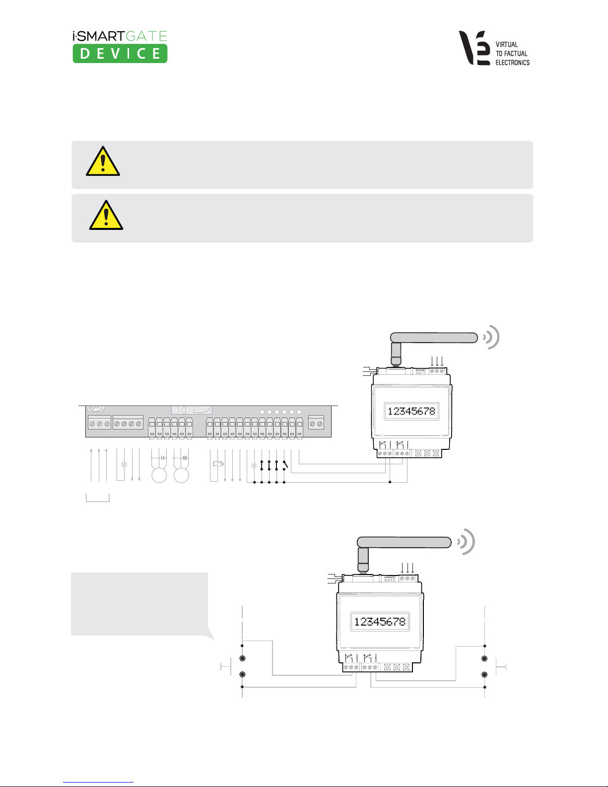
2. Wiring the iSmartGate-01W ................................................................................................
2.1 Wiring supply power ........................................................................................................
2.2 Wiring Load .....................................................................................................................
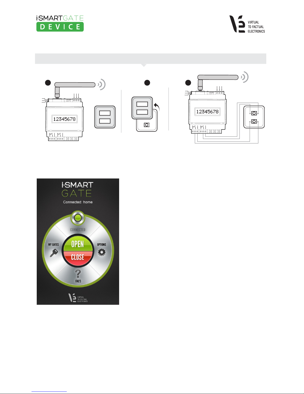
2.2.1 iSmartGate GARAGE Mode Wiring........................................................................
2.2.2 iSmartGate PULSE Mode Wiring..........................................................................
2.23 iSmartGate ON/OFF Mode Wiring.......................................................................
3. 3. Network........................................................................................................................
3.1 Step 1: Connecting your iSmartgate-01W to the Wi-fi router or AP....................................
3.2. Step 2: Find the iSmartgate-01W on your LAN network...................................................
3.3. Step 3: iSmartgate-01W network options configuration...................................................
3.3.1 SSID Configuration............................................................................................
3.3.2 Wi-fi Security Settings Configuration..................................................................
3.4 Step 4: AP / Wi-Fi router Configuration............................................................................
3.5. Step 5: Verification.........................................................................................................
3.6. Troubleshooting Guide..................................................................................................
4. How it works...................................................................................................................
4.1 GateName, Password, Port, Ipcast and Working Mode configuration.................................
4.2 GateName configuration................................................................................................
4.3. Password Configuration..................................................................................................
4.4. Working Mode Configuration..........................................................................................
4.5. Port Configuration..........................................................................................................
4.6. IP Broadcast Configuration.............................................................................................
4.7.Network Factory Default.................................................................................................
5. Upgrade Firmware............................................................................................................
6. iSmartgate App configuration .........................................................................................
6.1 How to add a door........................................................................................................
6.2 App Options...................................................................................................................
3
3
4
5
6
6
7
7
9
10
11
12
13
14
14
15
16
16
17
18
18
19
19
20
20
21
23
24
26
27
29

1. iSmarGate-01W Instructions for use
iSmartGate-01W www.v2fe.com
1.1 Quick Starter
-Wire up iSmartGate01W to our garage control panel. See section 2.
-Configure the network requirements on the iSmartgate-01W. See section 3.
-Configure the iSmartgate-01W according to the desired mode. See section 4
1. The desired name for the door. The default name is "home", but you can change it for anyone you want.
Just take into account that it has to be no more than 8 characters, in lowercase.
2. The desired password. The default password is "12345678". You can change it, just take into account that
it has to be 8 numeric characters.
3. The IP Broadcast of our network. The default one is "192.168.1.255"
4. The network port. The default one is 8001.
5. The mode you want the device to work, The default setting is "Garage"
Lastly, open the iSmargate app on your smartphone, and follow MY GATES > ADD GATE . You will be asked for
the follwing data, just be sure to complete all these fields with the same data entered in the iSmartgate Device:
1. Gate Name
2. Port
3. Password
4. Mode
INSTALLATION MANUAL · iSmartGate 01W · English / REV.3 3
NOTE
The iSmartgate-01W IS NOT AN AccessPoint (AP). It works as a CLIENT device (AP Client).
Therefore, it requires an AP network device (AP Wi-FI, Router Wi-Fi).
The iSmartgate-01W works as a plug-in for any garage door. It comes with 2 relay outputs that can be controlled with
any iOS / Android smartphone.
These 2 outputs need to be connected to the existing garage door's control panel.
In order to allow the iSmartgate-01W get connected to the smartphone, you will need either an Access Point Wi-fi (AP)
or a router Wi-fi. The iSmartgate-01W will connect through Wi-fi to the router/AP, and so will do the smartphone, once
it has the iSmartgate App installed. This, our smartphone and the iSmartgate device will be able to get connected
eachother.
Before proceeding with the installation, please read safety instrucions in section 1.2
In order to allow the iSmartgate App get connected to iSmartgate-01W, you need to complete the following steps:
Next, you need to put the next data, using the buttons and the display on the device:
It's Not necessary to put here the IP broadcast

1.2 Safety Instructions
INSTALLATION MANUAL · iSmartGate 01W · English / REV.3 4
iSmartGate-01W www.v2fe.com
The electrical installation of the iSmartgate-01W should be done by a professional.
Please read carefully all these instrucions before installing and starting to use iSmartgate.
Please follow all the instructions in detail in order to avoid personal injuries or
damage to third party devices.
The iSmartgate-01W is not adequate for really sensible installations or to control very
precise processes, as either a WI-FI / Ethernet network failure or a power failure can not
guarante a secure control.
The iSmartgate-01W must not be used in any place where it can be in touch with
explosive material or medical applications.
ATTENTION
The smartphone needs to be connected via WI-FI to the same network where the iSmartgate-01W is.
(See section 6. iSmartgate App configuration).
Once the network device is configured with this two steps:
· connected to the gate
· our telephone connected to Wi-Fi to the same LAN as the router (with the parameters configured properly)
By opening the application on your smartphone you’ll can open or close the door garage.
All settings can be made in a very simple way without specific knowledge of any programming language or PC.
NOTE
VIRTUAL TO FACTUAL ELECTRONICS, S.L. will never be responsible for any possible injury or damage
to people or objects that may occur due to an incorrect use or by not following these instructions.
Additionally, VIRTUAL TO FACTUAL ELECTRONICS S.L. will not accept any responsibility for third
party apps using it, or for any use of the iSmartgate-01W or its application, which is not specified
in this manual.
ATTENTION
ATTENTION
ATTENTION

INSTALLATION MANUAL · iSmartGate 01W · English / REV.3 5
iSmartGate-01W www.v2fe.com
1.3 Examples of use of the application
1. Garage Door Control (Open / Close)
2. Blinds Control (Open / Close)
3. Lighting Control, Irrigation Systems Contol ( ON / OFF)

INSTALLATION MANUAL · iSmartGate 01W · English / REV.3 6
iSmartGate-01W www.v2fe.com
2. Wiring the iSmartGate-01W
2.1 Wiring supply power
The electrical installation of the iSmartgate-01W should be done by a professional.
Please follow all the instructions in detail in order to avoid personal injuries
or damage to third party devices.
ATTENTION
L
N
P. E
Connect the wiring supply as it is shown in the following scheme.
Figure 2. Wiring supply Scheme
A maximum 240 Vac must never be surpassed.
This device is ready to use both with 110
Vac and 220 Vac.
Installation and Disconnection must be done without power supply in order to avoid
possible accidents.All regulations and rules must be taken into consideration when
installing the iSmartgate-01W device. The electrical installation of the iSmartgate-01W
should be done by a professional.
ATTENTION
iSmartGate-01W
LED STATUS
LED OUTPUT 1
LED OUTPUT 2 110/220AC
SEL BACK OK
RELAY 1 RELAY 2
Wi-Fi

INSTALLATION MANUAL · iSmartGate 01W · English / REV.3 7
iSmartGate-01W www.v2fe.com
2.2 Wiring Load
Installation and Disconnection must be done without power supply in order to avoid possible accidents.
All regulations and rules must be taken into consideration when installing the iSmartgate-01W device.
The electrical installation of the iSmartgate-01W should be done by a professional.
ATTENTION
Before to connect the load to the device outputs, check figure 6 for the maximum current
and voltage supported by iSmartGate-01W (http://www.v2fe.com/how-it-works1.html).
ATTENTION
2.2.1 iSmartGate GARAGE Mode Wiring
The iSmartGate-01W has 2 voltage free outputs: RELAY 1 and RELAY2 , to connect with electric or electronic
devices. If you want to control your Garage Door, you need to configure the iSmartgate-01W with the GRG Mode
(Garage mode). If in our iSmartGate APP we have set up the door with GRG MODE, we have to connect the device
as the following scheme:
You can also choose to connect
the iSmartgate-01W to the
Garage Internal Wall Switch,
as in the following scheme:
Figure 3. Connection of the iSmartgate-01W
to a standard Garage Door Control Panel
27
26
25
24
23
22
21
20
19
18
17
16
15
13
12
11
10
9
8
7
6
5
4
3
2
1
M1 M2
N
GND
F
POWER SUPPLY
CCURTESY
LIGHT
FLASHING LIGHT
Max 40w
MOTOR 2 CLOSE
MOTOR 2 COMMON
MOTOR 2 OPEN
MOTOR 1 CLOSE
MOTOR 1 COMMON
MOTOR 1 OPEN
CLOSE
OPEN
P. P.
PHOTO1
PHOTO
STOP
SCA
COM
PHOTOTEST
24 V
200mA
ELECTRIC LOCK
12 Voc MAX 25 W
LED STATUS
LED OUTPUT 1
LED OUTPUT 2
P. E N L
110/220AC
SEL BACK OK
RELAY 1 RELAY 2
Wi-Fi
Actual Wiring
NEW Wiring
OPEN
button
Inside
CLOSE
button
Inside
Actual Wiring
NEW Wiring
LED STATUS
LED OUTPUT 1
LED OUTPUT 2
P. E N L
110/220AC
SEL BACK OK
RELAY 1 RELAY 2
Wi-Fi
Figure 4a. Connect iSmartGate to your internal garage wall switch.

INSTALLATION MANUAL · iSmartGate 01W · English / REV.3 8
iSmartGate-01W www.v2fe.com
Once the iSmartgate App is configured and is able to connect to the
iSmartgate-01W (see sections 3,4, 6), we are ready to tap on the app's
OPEN button. Automatically, RELAY1 on the iSmartphone Device will
be activated for 5 seconds, sending the instruction to open the door
to the Garage Door Control Panel. On the other hand, as soon as we
tap on the CLOSE button on our iSmartgate App on the smartphone,
RELAY2 will be activated for 5 seconds, sending the instruction to
close the door to the Garage Door Control Panel.
Function "GRG" or Garage is the default mode and the more suitable
to open the Garage Door using the iSmartgate App. However, there
are other modes available on the iSmartgate-01W that can be used
with the app. (See sections 2.2.2 and 2.2.3)
Figure 5. As soon as the iSmartgate App
is connected, you will be able to read:
"Connected" and the circle line will appear
in green.
Figure 4b. Steps to connect iSmartGate to your garage remote controller
You can also choose to connect the iSmartgate-01W to the Garage Remote Controller, following this 3 steps:
1 2
OPEN
CLOSE
iSmartGate-01W
Garage door
opener controller iSmartGate-01W Garage door opener controller
3
Open the Garage door
opener controller
OPEN
CLOSE
LED STATUS
LED OUTPUT 1
LED OUTPUT 2
P. E N L
110/220AC
SEL BACK OK
RELAY 1 RELAY 2
Wi-Fi
LED STATUS
LED OUTPUT 1
LED OUTPUT 2
P. E N L
110/220AC
SEL BACK OK
RELAY 1 RELAY 2
Wi-Fi

INSTALLATION MANUAL · iSmartGate 01W · English / REV.3 9
iSmartGate-01W www.v2fe.com
2.2.2 iSmartGate PULSE Mode Wiring
As iSmartgate-01W has two free potential outputs, it allows to control opening and close of the following elements:
· Awnings · Blinds ·Curtains
In case the AC current of the motor we need to control is equal or below the data shown on figure 6,
you need to install the iSmartgate-01W as follows:
In order to do so, it is important to take into account
which is the maximum ELECTRIC CURRENT at witch
work the electric motor you want to control, which
should never surpass the values shown on figure 6.
In most cases, the existing control devices for those
elements already come with a relay incorporated on
it, so that we will not have to worry about the maxi-
mum elecrtic current.
In case the electric motor of the device we want to
control has higher DC current, you will need to add
an INDUSTRIAL CONTACTOR between the
iSmartGate-01W and the electric motor.
Figure 6. DC Current / DC Voltage for each
of the RELAY outputs
Figure 7. Wiring to control
awnings, blinds, etc.
L
N
iSmartGate-01W
M1
The electric element connected to
the iSmartgate Device needs to
have its own limit switch in
order to stop the action on a safe
way at any time, one at the upper
limit and other in the lower
end of the process.
ATTENTION
LED STATUS
LED OUTPUT 1
LED OUTPUT 2
P. E N L
110/220AC
SEL BACK OK
RELAY 1 RELAY 2
Wi-Fi

INSTALLATION MANUAL · iSmartGate 01W · English / REV.3 10
iSmartGate-01W www.v2fe.com
Once you have your smartphone connected to the iSmartGate-01W and configured with the PUL (Pulse) MODE,
you will be able to raise or lower the blinds, awnings or curtains as explained below:
· As far as you tap OPEN and keep it pressed, the element (blind/awning, curtain) will keep lifting up, as RELAY 1
(open) will be activated. As soon as you stop tapping the OPEN button, the OPEN action will be stopped.
· When pressing CLOSE, the opposite happens: the element (awning, blind, curtain) will start going down, as
RELAY 2 (CLOSE) will be activated. As soon as you stop tapping the CLOSE button , the action will stop.
2.2.3 iSmartGate ON/OFF Mode Wiring
Last, let's see how the iSmartgate-01W can also be configured as a ON/OFF mode (O/O).
Using this mode, you will be able to control the on and off of domestic elements such as lighting elements, electric
appliances, etc..
ON/OFF Mode allows the iSmartGate-01W to switch indepently 2 different LOADS (on and off).
· When you tap OPEN on the iSmartgate App on your smartphone, the LOAD connected to Output1 will go ON.
When tapping OPEN again, the LOAD connected to Output1 will go OFF.
· When you tap CLOSE on the iSmartgate App on your smartphone, the LOAD connected to Output2 will go ON.
When tapping CLOSE again, the LOAD connected to Output2 will go OFF.
You need to install it as the Figure 8 shown below:
Figure 8. Load control in MODE ON/OFF
L
N
LOAD 1 LOAD 2
iSmartGate-01W
LED STATUS
LED OUTPUT 1
LED OUTPUT 2
P. E N L
110/220AC
SEL BACK OK
RELAY 1 RELAY 2
Wi-Fi

INSTALLATION MANUAL · iSmartGate 01W · English / REV.3 11
iSmartGate-01W www.v2fe.com
Do not exceed the RELE'S output maximum DC current. See graphic on Figure 6.
ATTENTION
3.Network
The iSmartgate-01W is a netwok device which needs to connect to the home's WLAN where it is going to be used.
This WLAN needs to provide a Wi-Fi device protected with password. Usually, the standard router used for domestic
Internet connections is already Wi-fi, and is the one you can easily configure to connect your smartphone to the
iSmartgate-01W (Connection to Internet is not necessary).
Never use iSmartgate to control safety or electromedical equipment from whom a life
of an individual or an animal can be depending on.
ATTENTION
Figure 9. Network connection scheme
INTERNET
Wi-Fi
Wi-Fi
110/220AC
DISPLAY 1X8
P1 P2 P3
OUT OPEN OUT CLOSE
The iSmartgate-01W IS NOT AN AccessPoint (AP). It works as a CLIENT device (AP Client).
Therefore, it requires an AP network device (AP Wi-FI, Router Wi-Fi) and a Windows PC to set up.

INSTALLATION MANUAL · iSmartGate 01W · English / REV.3 12
iSmartGate-01W www.v2fe.com
LED INDICATORS
YELLOW
· Constant light: iSmartgate-01W is connected to an Access Point
· Flashing light: iSmartgate-01W is searching available Wi-fi connections to connect.
GREEN: Network activity
Link status / Integrity
Network activity / Diagnostic
iSmartgate Network configuration instructions:
3.1 Step 1: Connecting your iSmartgate-01W to the Wi-fi router or AP
Do not switch on your iSmartgate device yet.
As your iSmartgate-01W is an AP client, it has no instructions on which Wi-fi AP is the one it should connect,
so it will connect to the first AP non WEP/WPA password protected Wi-fi available.
Therefore, we need to configure our Wi-fi AP or Wi-Fi router disabling the password, so that the AP remains open.
Please take into account that you have to look on your smartphone if there are other open AP Wi-fi (not password
protected), as the iSmartphone-01W can connect to them.
If this is your case, you also need to change your router's or Wi-fi AP SSID, naming it "Connect". This way, as the
iSmartgate-01W finds more than one open Wi-fi network connection, will choose the one which name's starting
with "Connect".
Once we have set up all these points, we are ready to switch on the iSmartgate-01W, and the yellow led
should be standing on, while the green led should be flashing.
2
1
2
1

INSTALLATION MANUAL · iSmartGate 01W · English / REV.3 13
iSmartGate-01W www.v2fe.com
Figure 10. Seaching the iSmartgate
3.2. Step 2: Find the iSmartgate-01W on your LAN network
Once the iSmartgate-01W is connected to the AP or WI-fi router and switched on, we will use a computer connected
to the same network in order to find it and therefore configure the iSmartgate device.
You have to connect through the ethernet, your PC to the AP or Wi-fi router.
In order to access to the iSmartgate-01W internal configuration, you will need to use Digi Device Discovery
(if you don't have it, you can download it at www.v2fe.com).
Then you need to run the program, by clicking "dgdiscvr.exe" (Digi Device Discovery is owned by Digi Inc.)
In case the iSmartgate-01W device does not appear on the screen, please wait for 5 minutes and if it still is not
showing up on the screen, click on "Refresh View". If you have repeatedly searched the iSmartgate-01W with no
success, it may be connected to another open network, not ours, this means that you need to go back to step 1 and
start the process again.
If you have found the iSmartgate-01W, please move on to step 3.3.

INSTALLATION MANUAL · iSmartGate 01W · English / REV.3 14
iSmartGate-01W www.v2fe.com
3.3. Step 3: iSmartgate-01W network options configuration
Once we have found the iSmartgate-01W using Digi Device Discovery Software, you have to click on
"Open Web Interface".
You have to fill the following fields to enter:
LOGIN: isg
PASS: 12345
Once introduced, you will get access to the Web Configurator.
On this step, you will configure the iSmartgate-01W so that it connects to the AP or Wi-fi router your desired SSID
and password. At this point, your AP or wi-fi router is not 100% configured as you have temporally disabled its
password and it is possible that you have also needed to change its SSID. Therefore, now it's the moment to set
up the iSmartgate-01W with the desired parameters, so that later it will connect to your network with those same
parameters.
Haremos click en network y en WiFi LAN settings:
· Network Name; Please write here the name you want for your Wi-fi network, as you will later need to give the
same input data to your AP or Wi-fi router.
· Connected to Access Point: You need to select this option so that the iSmartgate-01W only connects to AP or
routers.
Lastly, if desired, you can configure channel and country.
Click "Apply" (not event Reset device).
3.3.1 SSID Configuration

3.3.2. Configuración de las WiFi security Settings
Click on "network" and then click on "WIFI Security Settings".
V2FE recommend to use the WPA encryption, configuring the computer iSmartGate-01Was follows:
Last, set up the WPA password. Then we´ll have to insert it to the Access Point o Router.
Click on “Apply”.
iSmartGate-01W device will show a message to tell us that it took one minute to calculate encryption.
Once the minute ends, reset the device (Administration -> reboot).
INSTALLATION MANUAL · iSmartGate 01W · English / REV.3 15
iSmartGate-01W www.v2fe.com

INSTALLATION MANUAL · iSmartGate 01W · English / REV.3 16
iSmartGate-01W www.v2fe.com
If the AP or Wi-fi router has been successfully configurated, the iSmargate-01W should be connected to it.
To verify it, you need to run the dgdiscvr.exe and, if this software is able to find the iSmartGate-01W,
the network configuration has been successfully completed.
In any other case, go back to step 3.6.
3.5. Step 5: Verification
To avoid communication errors, you should set the parameters in WiFi
AP or Router, which will connect the equipment iSmartGate-01W, as follows:
(in general way)
Wifi Settings -> ADVANCE -> 54G MODE -> 802.11b Only
ATTENTION
Reference example:
Once you have configured the iSmartGate-01W with the SSID and the safety options,
you need to configure the AP or Wi-fi router with same data.
Please check that:
Once you have finished configurating your AP or wi-fi Router, switch off, and the switch on again
your iSmartgate-01W.
Wait until the yellow LED on your iSmartgate stays illuminated (not flashing) to move on to the next step.
If this doesn't happen, go back to step 3.6.
· The PC where the dgdiscvr.exe is running, is correctly connected to the
Ap or Wi-fi router through an ethernet connection.
· The iSmartGate-01W is close to the AP or router, in order to avoid coverage problems.
3.4 Step 4: AP / Wi-Fi router Configuration

INSTALLATION MANUAL · iSmartGate 01W · English / REV.3 17
iSmartGate-01W www.v2fe.com
If you are reading this section, it means that after trying to configure both iSmartGate-01W and AP, with our SSID
and security settings, it has not been possible to connect them.
Firstly, it is really important to be sure that you have typed exactly the same SSID and password on both network
devices (AP or Wi-fi router and iSmartgate Device).
At this stage, it is not possible to access the iSmartGate-01W, as it will try to connect to a network which will
have incorrect SSID or password.
Therefore, you will need to RESET the iSmartGate Device to the default factory settings:
1. Press the SEL button on the iSmartgate-01W until the display shows: "6-ResNet"
2. Press OK
3. You will be asked again if you are sure to RESET the network configuration. Press OK.
4. You will be asked again if you are sure to do so. Press OK.
5. Wait until the iSmartGate-01W restarts.
At this moment, the iSmartgate-01W will start again to search for an open Wi-fi network to connect.
Please go back to section 3.1.
3.6. Troubleshooting Guide

INSTALLATION MANUAL · iSmartGate 01W · English / REV.3 18
iSmartGate-01W www.v2fe.com
4. How it works
In order to configure the iSmartgate-01W parameters, you have to use the three buttons and use them according
to the information appearing on the display.
· BUTTON 1: SEL
Selection Function: It will help you navigate through the different available options.
· BUTTON 2: CANCEL/BACK/MODIFY
This button will allow you to go back to the main menu or the previous selected option.
When we are typing data, this button rotate the alphanumeric value.
· BUTTON 3: OK
Confirmation button. Once you press it, you will either enter in the selected option,
or accept the selected parameters.
4.1. GateName, Password, Port, Ipcast, and working Mode configuration
In order to control the iSmartgate-01W with our smartphone, it is important to ensure a secure connection
between them, avoiding third party equipments the access to it. To provide this safety connection, the iSmart-
gate-01W needs to have the following parametres completed successfully;
· GateName: The door's name
· Password: Numeric password to access the door control
· Port: Network Port using the TCP/IP communication.
· Working Mode: "Garage", "Pulse", or "On/Off".
Those 4 parameters, all together, will create a unique code that will be used to encript all the communications.
This is why those 4 parameters need to be introduced exactly the same way on the iSmartgate-01W and
our smartphone.
Aditionally, you will also have to configure your network's IP broadcast to ensure that the device can transmit
correctly. (See section 4.6)
Once the iSmartgate is switch on, the display screen will inform you about all the selected configurations.
Reminder:

INSTALLATION MANUAL · iSmartGate 01W · English / REV.3 19
iSmartGate-01W www.v2fe.com
4.2 GateName configuration
This parameter will allow you configure the door's name, with the same data on your iSmargate App on your
smartphone. The default door's name is "home". if you want to change it,please follow this steps:
1. Press the SEL button until the display screen shows the following info: "2-SET GN"
2. Press OK
3. The display message will ask you if you are sure you want to change your door's name. Press OK.
4. As you press OK, the existing door's name will appear on the display. You will have to change the
door's name one character at a time. The character flashing is the one you are changing. To do that,
simply push the CANCEL button (button #2). To move on to the next character, press SEL button (button #1).
5. 5.Once you have the desired door's name, press the OK button (button #3).
6. If everything worked well, you will read "SAVED!" on the display.
4.3 Password Configuration
This parameter helps you configure your door's password. The password entered in the iSmartgate-01W will have
to be the same than the one on your iSmartgate App.
The default door's password is "12345678". This field only accepts numeric characters.
In order to change the default password, which is strongly recommended, please follow this steps:
1. Press button 1 until the tet "1-SET PW" appears on the display.
2. Press OK (button 3).
3. The display message will ask you if you are sure you want to change your door's password. Press OK.
4. As you press OK, the existing password will appear on the display. The numeric character which is flashing
is the one you are about to change. To do so, press button #2. To move on to the following character,
press button SEL (button #1).
5. As soon as you have the door's desired password, press the OK button (button #3).

INSTALLATION MANUAL · iSmartGate 01W · English / REV.3 20
iSmartGate-01W www.v2fe.com
4.4. Function Mode Configuration
This is a very important parameter as it will decide the way the iSmartgate-01W works.
As with the previous configurations, the selected mode will be the same running on your iSmartgate App on your
smartphone. The default mode for this parameter is “Garage”.
If you want to change it, just follow these steps:
1. Press the button #1 until it shows the following message: "3-TYPE"
2. Press OK (button #3)
3. The display message will ask you if you are sure you want to change the function mode. Press OK.
4. As you press the button #1, you will be able to navigate through all the existing modes.
5. As soon as you see on the display the desired Function mode, press the OK button (button #3).
4.5. Port Configuration
This is the network parameter which defines the port in which the communication will be realized. You don't
need to modify it, unless you have more than one iSmartgate device in the same LAN/WLAN network. If this is the
case, you will need to select a different port for each of them, bearing in mind that them have to be comprended
between port 8000 and 65535.
The default port configuration is “8001”.
If you want to change it, just follow these steps:
1. Press the button #1 until it shows the following message: "3-PORT"
2. Press OK (button #3)
3. The display message will ask you if you are sure you want to change the door's network port.
Press OK (button #3).
4. As you press OK, the current enabled network port will show up on the display. The numeric character which
is flashing is the one you are about to change, to do that press button #2. Once it is correct, you can move
on to the next character pressing the SEL button (button #1).
5. Once you have the desired port selected, press OK (button #3).
Table of contents
Popular Garage Door Opener manuals by other brands

Roger Technology
Roger Technology H30/645 INSTRUCTIONS AND RECOMMENDATIONS FOR THE INSTALLER

Chamberlain
Chamberlain LIFTMASTER 3275 owner's manual

Genie
Genie GCL NEMA 4 Installation supplement

EINHELL
EINHELL BGT 63 Mounting and operating instructions

FAAC
FAAC E-SC 1600 instruction manual

Chamberlain
Chamberlain 2565 1/2 HP owner's manual