ENGLISH EDITION 2016
Construction Manual
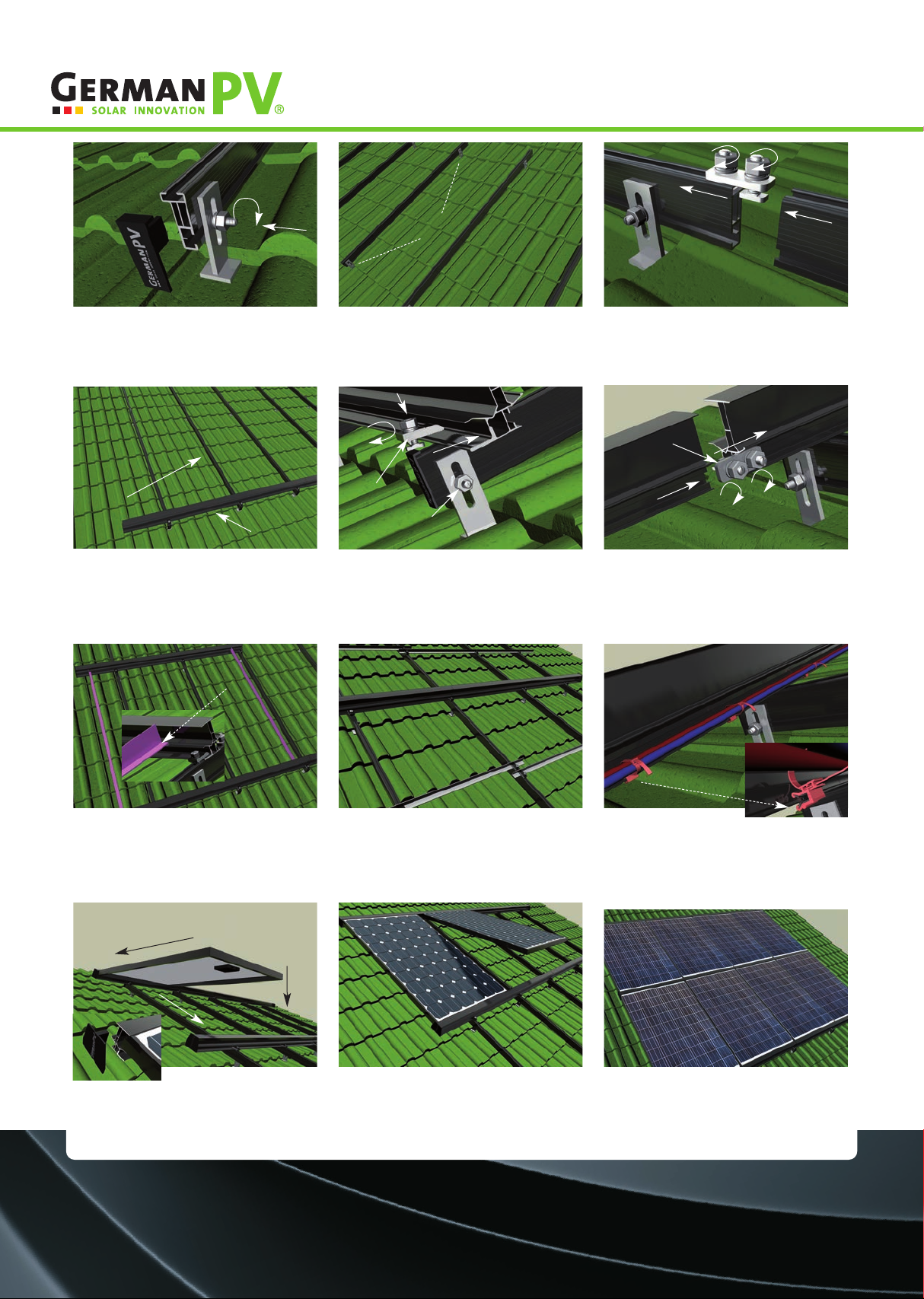
Mounting
System PVclick (short version)
www.germanpv.com
The mounting system PVclick is a lay-on system that was
especially developed for on-roof installation.
The application of the system is designed for rafter
spacing between 0.5 m up to *1.8 m (* see long version).
Depending on the roof cladding in situ, one or several roof
tiles have to be taken out of the brick bonding for instal-
ling the rafter anchors (1).
For precise installation of the rafter anchors, the area of the anchor brackets has to be ground either on one or on both sides, depending on the type of roof tile. Particular attention has
to be paid to the completely planar application of the anchor flange plate onto the rafter (optimal distribution of the load into the background construction).The rafter anchor included
in the delivery (1) is suitable for standard battens 30 x 50 mm. Stronger battens (e.g. 40 x 60) require the installation of laminar pitch elements (e.g. plywood, laminated paper).
The system components of the mounting system PVclick are made of aluminium, stainless steel (A2) and synthetic materials. The system profiles are delivered in powder coated design
coloured matt black. The distance of the installed generator surface to the outer perimeters of the roof (ridge, eaves, gable board) has to be considered, especially regarding increased
suction forces in the corners and on the edges or the existence of exterior lightning protection (arrester on the roof, gable board).
The rafter anchors (1) have to be arranged within the levelled
down area of the roof tiles. The bore holes for fixing the an-
chor plates should align on the rafter as centred as possible
Three wafer-head screws M8 x 100 (2) fasten the rafter an-
chor (1) to the rafter.A cordless screwdriver with bit holder
(Torx 40) is a suitable tool for this.
Important: Mounting several rafter anchors on one rafter
requires their vertical alignment.
The optional installation of tin roofing tiles (if available in the product range) below the rafter anchor minimises the risk of potential cracks in the roof tile due to high loads (snow-
intensive zones) and therefore is recommended.
Klemmverbinder (5)
Sparrenanker (1) min. 0.5 - 1 m
z.B. »Frankfurter Pfanne«
Sektor des Sparrenankers
(Steg) mit Trennschleifer
ausschleifen
uftspalt
1-2 mm
beachten
z.B. Dachlatte
30 x 50 mm
(1)
min. 25 mm z. B. Dachlatte
40 x 60 mm
(1)
(2)
Flucht beachten!
Important notice!
Before carrying out the installation procedures described
below, the professional association rules for health and
safety at work BGR 203 (roof work), the DIN EN 516 provisi-
ons for accessing the roof, the guidelines for selection and
use of roofing battens and planks of the construction indu-
stry's professional associations and all other regional gui-
delines and regulations reflecting the state of technology
are to be appropriately taken into consideration. Before
mounting a PV system, the suitability of the roof construc-
tion and the arrangement of fastening points (fixed points)
for directing the load into the background construction
have to be verified in a structural analysis, for which the
building owner is responsible. GermanPV GmbH is not liable
for the suitability of the roof background construction. The
mounting system PVclick was tested and verified in a struc-
tural analysis on the basis of the standard DIN 1055 Part 4
and Part 5 for application in wind load zones 1-4, snow load
zones 1-2a, altitudes above sea level of up to 999 m and
roof slopes between 15° - 45°. For more detailed informa-
tion on the application conditions of the mounting system
please refer to the long version (www.germanpv.com).
Moduleinschubprofil (7) Ankerprofil (6)
Endkappe groß (8)
Endkappe klein (9)
Profilverbinder (4)
Hammerkopfschraube (3) Tellerkopfschraube M8 x 100 (2)