Isolite E3-MAC Series User manual

1
E3-MAC Series by Isolite
Installation/Operation Manual for E3-MAC Emergency Lighting Central Inverter System
1.0KW –3.0KW Models
1KW Model –Single Cabinet
IMPORTANT SAFEGAURDS
When using electrical equipment, basic safety precautions should always be followed including the
following:
READ AND FOLLOW ALL SAFETY INSTRUCTIONS
A. Do not use outdoors
B. Do not mount near gas or electric heaters.
C. Use Caution when servicing batteries. Battery acid can cause burns to skin and eyes. If acid is
spilled on skin or in eyes, flush acid with fresh water and contact a physician immediately.
D. Equipment should be mounted in locations and at heights where it will not readily be subjected
to tampering by unauthorized personnel.
E. The use of accessory equipment not recommended by the manufacturer may cause an unsafe
condition.
F. Do not use this equipment for other than intended use
This unit contains lethal voltages. There are no user serviceable parts inside. Only authorized service
personnel are to be used for service.
SAVE THESE INSTRUCTIONS
The installation and use of this product must comply with all national, federal, state, municipal or local
codes that apply. Please read this manual thoroughly before installing and operating this Central
Inverter System. For assistance please call Technical Service at 800-967-5573 and speak to a technician
during normal business hours (EST).

2
Table of Contents
1.0 Introduction 4
1.1 Mechanical 4
1.2 Electrical 4
2.0 Receiving and Storage 6
2.1 Inspection 6
2.2 Storage 6
3.0 Installation 7
3.1 Location 7
3.2 Operating Environment 7
3.3 Ventilation 7
3.4 Mounting Guidelines 7
3.4.1 Clearance 7
3.4.2 Floor Preparation 7
3.4.3 Knockout Locations 9
4.0 AC Connections 10
4.1 Removing the Front Cover 10
4.2 Removing the AC Breaker Cover 11
4.3 Installing the Input Wires 11
4.4 Installing the Output Wires 12
5.0 Battery and DC Connection 13
5.1 Battery Inspection 13
5.2 Battery Installation 13
5.3 DC Voltage of System 13
6.0 Start up and Shut Down Procedures 17
7.0 Specifications 18
7.1 Input / Output Voltage and Current Chart/Matrix 19
8.0 MMI (Man Machine Interface) 20
8.1 Introduction 20
8.1.1 System Test Button 20
8.1.2 Alarm Silence Button 20
8.1.3 Keypad and Display 21
8.1.4 SD Card Slot 21
8.1.5 USB Slot 21
8.2 Main Menu 21
8.3 Meter Menu 21
8.4 Alarm Menu 21
8.5 Event Log 22
8.6 Test Log 22
8.7 Alarm Log 22
8.8 User Menu 23
8.8.1 Date and Time 23
8.8.2 Month Test 23
8.8.3 Year Test 23
8.8.4 Low VAC Alarm 23
8.8.5 High VAC Alarm 23
8.8.6 Low Battery Alarm 23
8.8.7 Near Low Battery Alarm 23

3
8.8.8 Utility Failure Alarm 23
8.8.9 High Temperature Alarm 24
8.8.10 Time Delay 24
8.8.11 Load Reduction 24
8.8.12 Relay 1 24
8.8.13 Relay 2 24
8.8.14 Backup Logs 24
8.8.15 Contact Name 24
8.8.16 Contact Phone 24
8.9 Factory Setup 25
8.10 System Info 25
9.0 System Operation 25
9.1 Start-Up Mode 25
9.2 Battery Charging Mode 26
9.3 Switched Output 26
9.4 Inverter Power Mode 27
10.0 Warranty 28
10.1 Technical Service and Support 26
10.2 Return Material Authorization (RMA) 28
11.0 Maintenance and Service 29
11.1 Battery Maintenance 30
11.2 Battery Replacement 30
12.0 Web Interface 31
12.1 User Setup 31
12.2 Control Panel 31
12.3 User Setup 32
12.4 Alarms Page 32
12.5 Charts and Graphs 33
12.5.1 Temperature 33
12.5.2 Output VA 33
12.5.3 Battery Voltage 33
12.5.4 Discharge Events 33
12.5.6 Discharge Power 34
12.6 System Logs 34
12.6.1 Alarm Log Page 34
12.6.2 Test Log Page 34
12.6.3 Event Log Page 34
12.6.4 Discharge Log Page 34

4
1.0 Introduction
This Central Inverter System integrates the latest power electronics and microprocessor technology
which produces a pure sine wave power output intended for use in Emergency Lighting. The system is
very efficient on-line and typically has a standby power loss of only 2 percent of the systems total
capacity which means it is 98% efficient. This high efficiency and the ability to turn lighting loads on and
off using the optional switched load outputs make it ideal for energy saving and green initiatives. This
equipment was specifically designed for modern lighting loads and as such has very high inrush current
capability which are required for today’s LED drivers and electronic lighting loads. It is UL-924 compliant
for Self-Testing and Self Diagnostic and as such performs internal checks and tests and records them in
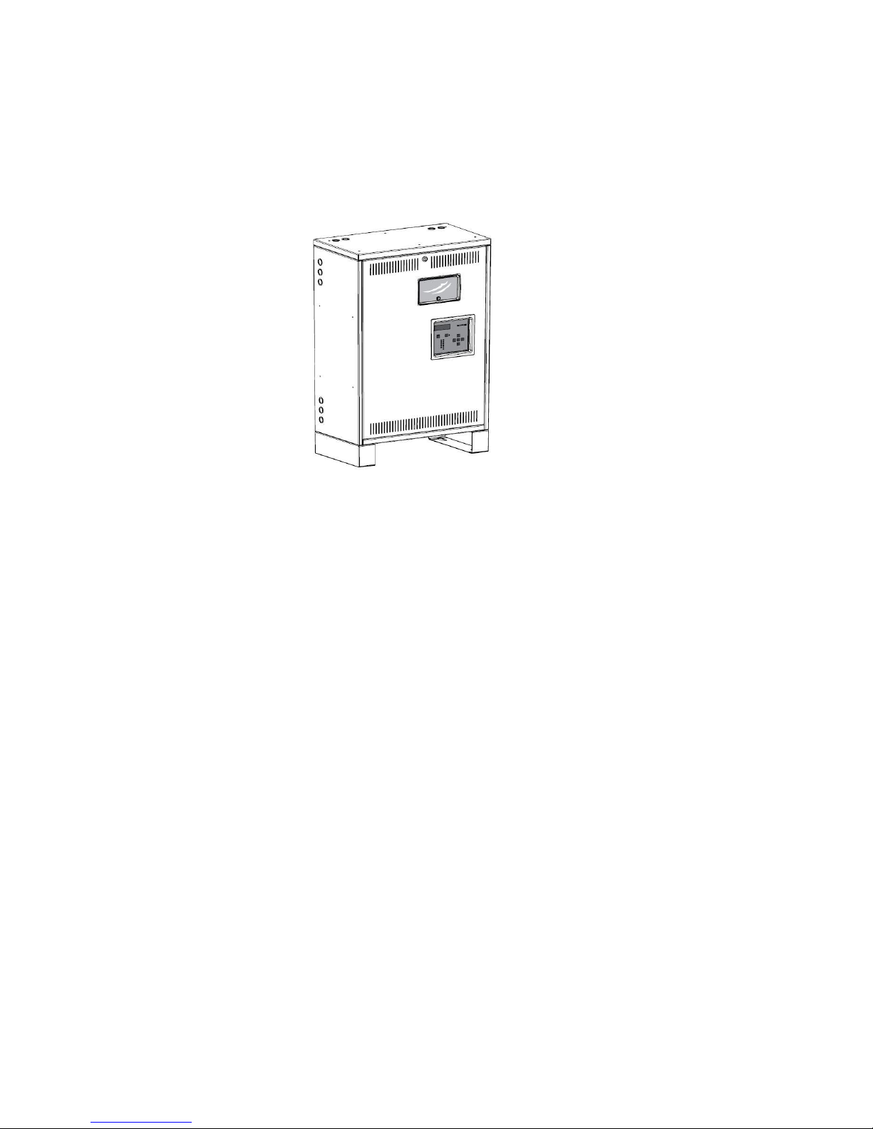
backup logs. The MMI (Man Machine Interface) which consists of a 5 button keypad and backlit LCD
display is very powerful and feature rich. Users can access all stored logs and diagnostic tools such as
meter functions, they can also change alarm functions and much more. The machine was designed on a
modular concept so virtually any voltage combination can be created using these modules including
single phase, split phase, and three phase.
1.1 Mechanical Features
This product was designed having the electrical installer in mind. It can be easily recognized as the
simplest and fastest Central Inverter installation in the industry for its KVA size and capabilities.
Batteries are Front Terminal type which makes connecting up the batteries extremely fast. Simply slide
the batteries into the cabinet, connect up the jumpers and connect the inter-shelf (model dependent)
wiring and the battery install is finished. All battery connections come to the front –this means no
reaching to the back through a string of batteries to make connections! The AC connections are also
very easy to accomplish with the contractor landing the inputs and outputs to either Circuit Breakers or
Terminals, Neutral wires are connected to a common neutral buss bar and Ground wires are also all
connected to a common ground bar. Contractor wiring is very similar to connecting to an electrical panel
in that there are knockouts on both sides and tops of the cabinet for easy conduit connection and then
wires are then easily run into the cabinet and connected to ground bars, neutral bars and circuit
breakers.
The machine was designed for Seismic Zone 4, has Powder Painted 14 gauge Cold Rolled Steel
construction with no visible outside bolts or rivets. Internally, it has all galvanized or painted steel parts
for all the modules and shelves that resist corrosion and provide durability and high quality.
1.2 Electrical Features
This product line has one of the most flexible voltage configurations in the industry due to its modular
design concept. Each module can be configured as 120 or 277 or 120/240. The modules can be arranged
in parallel, series or Wye connected. This gives the capability of producing voltages of single phase (L-N
and L-L), split phase (L-N-L), and three phase. By utilizing a modular concept, it provides scalability, quick
delivery and in the event of issues, very fast MTTR (Mean Time to Repair).

5
The Inverter utilizes a bi-directional converter that is either MOSFET or IGBT technology based on the DC
voltage of the system. The system does not require installers to go through a manual pre-charge and dis-
charge procedure to start the system up because these components are built into the Inverter Modules.
The overload capabilities of the system defined by its crest factor (minimum of 4.0) which means that
universal ballasts and drivers present no issue starting up on Inverter Power and it can sustain a
minimum of 400 percent for about a half second. During the charge mode when power passes through
the internal transfer device, the system can withstand inrush currents of several thousands of amps due
to its extremely high I²t rating of the breaker and inline fuse. The system has a 0.5 lead and lag power
factor capability and coupled with its fast transfer capability, it can power up ANY type of emergency
lighting fixture from HID, Quartz, LED, Fluorescent, Plasma, etc.
The batteries are charged using a three rate charging scheme and are temperature compensated. The
batteries used are a 10 year design life and while on float charge have practically zero ripple current
through the batteries thus providing the longest possible life. An optional pure lead battery is available
for use in higher temperatures to extend the batteries life. The battery string has galvanic isolation to
the system line neutral and ground which makes the install very safe. Any inadvertent short circuit from
a battery terminal to chassis will not cause any fault currents of any kind.
NOTE - This equipment is equipped with Brown-Out Circuitry. The set-point is around 85 percent of
nominal AC input voltage and is not user adjustable. Due to tolerances, the brown out may occur up to
86 percent of nominal. In the event of a Brown-Out (Very Low AC Input) the system will transfer to
Emergency Power and discharge the batteries.

6
2.0 Receiving and Storage
2.1 Inspection
The Cabinets and Batteries may be shipped on the same pallet or may be shipped separately. Upon
arrival please inspect the contents to ensure that no shipping damage has occurred. This is especially
important with the batteries –ensure that there are no cracks or leaks. If any damage has occurred
notify the shipping carrier immediately and submit a damage claim.
WARNING - Do not install damaged battery as this may cause an unsafe condition.
2.2 Storage
Storage before the installation is critical for the battery life expectancy and warranty. Store the batteries
indoors in a clean, dry and cool location. Storage at higher temperatures will result in accelerated rates
of self-discharge and possible deterioration of battery performance and life.
WARNING –The maximum storage time from shipment to initial charge is 6 months for batteries stored
at ambient temperatures no warmer than 77°F (25°C). For storage temperatures greater than 77°F
(25°C) the batteries must be recharged one (1) month sooner for every 5°F (3°C) increase above 77°F
(25°C).
Storage Temperature Storage Time
32°F (0°C) to 50°F (10°C) 9 Months
51°F (11°C) to 77°F (25°C) 6 Months
78°F (25°C) to 92°F (33°C) 3 Months
Storage at high temperatures will result in accelerated rates of self-discharge and possible deterioration
of battery performance and life. Storage times exceeding the above may result in plate sulfation, which
may adversely affect electrical performance and expected discharge performance and life.
Failure to install and charge the batteries as noted VOIDS the battery’s warranty.
DANGER -A battery can present a risk of electrical shock and high short circuit current.
Valve-regulated lead-acid (VRLA) batteries contain an explosive mixture of hydrogen gas. Do not smoke,
cause a flame or spark in the immediate are of the batteries. This includes static electricity from the
body. Use proper lifting means when moving batteries and wear all appropriate safety clothing and
equipment.

7
3.0 Installation
3.1 Location
NEC article 700 EMERGENCY CIRCUITS should be referenced for proper installation of a Central Inverter
System. Article 700 dictates that unit must be mounted in a permanent location. Choose a cool dry place
with normal ventilation and one which will allow easy access for testing and maintenance. Avoid a
location which could allow vandalism and tampering with. Avoid areas that would prohibit visual contact
with the heads up LED status displays.
3.2 Operating Environment
Choose a location that is controlled between 20 and 30 degrees C. for optimum battery life and
performance. The unit is UL listed between 20°C to 30°C (68°F to 86°F) because of battery discharge
performance results. Do not install in a wet or damp location. Do not install in environments that will
expose the unit to excessive temperatures like boiler rooms as this will significantly depreciate battery
life.
Heat is the determining factor of battery life. Every means should be made to keep the batteries in an
environment that keeps the batteries around 25 degrees C for rated battery life.
3.3 Ventilation
Choose a mounting location that is clean and dust free. Do not install in areas where there is particulate
from heavy industrial machinery, corrosive chemicals or welding or plasma cutting environments etc.
WARNING –Batteries for this system can weigh up to 60 pounds each. Ensure that the mechanical
mounting means can support this weight.
3.4 Mounting Guidelines
3.4.1 Clearance
The system is convection cooled and only uses forced air cooling under Inverter Power operation. Air
ventilation is through the front and uses convention so air flows from the bottom to the top. Since code
mandates that at least 3 feet of clearance is required for clearance to the front of the unit, no special
requirements for cooling are required.
WARNING - Never leave objects draped over the top of the unit which would prevent proper air flow.
Blocking proper air circulation may result in an over-temperature fault during Battery Charging or
Inverter Power mode depending upon ambient conditions.
3.4.2 Floor Preparation
Mounting holes are provided in the Cabinet Base for Floor Mounting purposes. The location of these
holes are at the base of the cabinet and will accommodate 3/8’ mounting hardware. Four mounting
holes are provided and all 4 should be used when floor mounting.

8
Figure 1 –Overall Dimensions
Diagram shows both side by side and top and bottom mounting configuration.
Top and Bottom mounting configuration is factory preferred for control panel access.
Battery Cables from Factory are sized for top and bottom mounting configurations.

9
3.4.3 Knockout Locations
EKO’s (Electrical Knock Outs) are provided on the Left side, Right side and also the Top side surfaces.
Ensure all metal conduit is secured and tightened creating a good connection to earth ground. Use an
Ohm-Meter to check that continuity between conduit and protective earth ground has been
established.
At no time is drilling allowed into the cabinet!
Drilling causes metal filings to be deposited on surfaces and could land on the Printed Circuit Boards and
cause short circuits.
WARNING –Drilling into cabinet may void warranty if metal filings causes unit failure.
Figure 2 –Knockout locations

10
4.0 AC Connections
WARNING –Only qualified personnel that are familiar with AC and DC installation techniques and codes
(such as an electrician) should perform the Installation.
WARNING –This system contains lethal AC Voltages. Because of these hazards of high voltage
electrocution, always shut down all sources of power before you install, maintain, or service the unit.
WARNING –Remove all rings, watches, and other jewelry before doing any electrical service or
installation work. Always wear protective clothing and appropriate personal protective equipment (PPE)
that is suitable such as eye protection when working near batteries.
4.1 Removing the Front Cover
All the connections for the AC input and output are located on the top side of the units’ enclosure. To
access the wiring area, simply remove the cover by turning the covers front latch 90 degrees CCW
(counter clock-wise). You will need a large flat blade (slotted) screw-driver for this.
Figure 3 –Standard AC Connections for Input and Output

11
4.2 Removing the AC Breaker cover
To access wiring to the breakers, remove the two ¼-20 screws from the plastic breaker cover with a 3/8
socket or nut driver and the circuit breakers cover will easily remove. This cover conceals the wiring area
and also provides a safety barrier so that fingers cannot inadvertently touch live parts after installation.
WARNING –Always re-install the AC Breaker cover to prevent accidental contact with live wires during
routine maintenance.
4.3 Installing the Input Wires
Once the Cover and Circuit Breaker cover are removed,
1. Ensure that the incoming AC voltage is the same AC voltage rating as the unit.
2. Ensure that the feed breaker from the panel has at least the same breaker rating as the input
breaker.
Once Feed Voltage and Breaker size is correct, connect the Utilities Feed Line voltage to the Input Circuit
Breaker. There will also be a dedicated position for Neutral, and Ground. Ensure that the connections
are tight by giving the wires a good pull and ensure that the wires are secured into the blocks.
Connection to these blocks will require a small flat bladed screw-driver for the neutral bar and a larger
flat blade (slotted) screw-driver for the ground bar. Connection to the circuit breaker works best with a
#2 Phillips head screw-driver.
NOTE - The circuit breaker to the far left is always the input breaker –Output breakers are always to the
right of the input breaker. Please check the labeling on the breaker cover for breaker number
assignments.
NOTE –AC Input and AC output wires must be run in separate conduit or raceways per NEC ARTICLE
700. Please ensure all codes and standards are observed.
NOTE –Ensure that the Neutral and Ground potential does not exceed 5 VAC for proper function.
Anything above 5 VAC typically indicates that there may be a grounding issue or inadequate conductor
size or continuity. This should be looked at immediately as it could cause a safety concern.
NOTE –Neutral and ground should never be tied together anywhere in the system. Always keep Neutral
and Ground wires separate and ensure no shorts occur.
NOTE –Neutral connections in the system are a “Pass Through’ which means Input and Output Neutrals
are directly connected.
NOTE –Never mix Neutrals on the building wiring (Non-Emergency) with the Emergency wiring.
Dedicated wiring is required by NEC code ARTICLE 700.

12
4.4 Installing the Output Wires
Connect the load wires to the provided terminal block labeled N. On. If switched loads were installed
from the factory, connect the switched loads to the breakers to the right of the input breaker. There are
dedicated neutral and ground blocks which should be shared for the AC input and AC output. Again,
ensure that the connections are tight by giving the wires a good pull and ensure that the wires are
secured into the blocks.
NOTE –“Wiring from an emergency source or emergency source distribution overcurrent protection to
emergency loads shall be kept entirely independent of all other wiring and equipment, unless otherwise
permitted” NEC ARTICLE 700 excerpt.
Figure 4 –Optional Output Circuit Breakers and Switched Command

13
5.0 Battery and DC Connections
WARNING –Only qualified personnel that are familiar with AC and DC installation techniques and codes
(such as an electrician) should perform the Installation.
WARNING –Remove all rings, watches, and other jewelry before doing any electrical service or
installation work. Always wear protective clothing and appropriate personal protective equipment (PPE)
that is suitable such as eye protection when working near batteries.
WARNING - Batteries contain tremendous energy and can explode if short circuited. Precautions should
be taken to eliminate possible short circuits. Do not install batteries until unit is completely mounted
and secured in a permanent location with all conduit and AC wiring connected.
5.1 Battery Inspection
Inspect the batteries for any physical damage such as cracks or any other sign of leaking electrolyte.
Batteries contain Sulfuric Acid which is highly corrosive. A leak from a battery will cause an unsafe
condition.
5.2 Battery Installation
The batteries used in this system are front access so no pre-wiring is required to the battery terminals.
Simply load the batteries into the cabinet in an orderly manner. If seismic bracing is provided, ensure
the brackets are secured.
Torque on all lugs to the batteries are 20 Newton Meters or 30 Inch Pounds.
NOTE –The cover should already be removed from installing the AC Input and Output wiring. Please
refer to section 4.1 for Cover Removal.
5.3 DC Voltage of System
The systems DC battery voltage is model dependent. Please see Figures 5-8 for specifics on
configuration.
All required cables are provided by the manufacturer.
NOTE –Battery potential has galvanic isolation from AC potential. Battery voltage measurement must
be performed with both meter leads connected to the battery terminals.

14
Figure 5–1KW / 48VDC Diagram
Figure 6 –2.2KW / 96VDC Diagram

15
Figure 7 –2.8KW / 120VDC Diagram
Figure 8 –3.0KW / 48VDC Diagram

16
Figure 9 –Optional Seismic Restraints Illustration

17
6.0 Start up and shut down procedures
Start-Up
After the AC input and output wires are connected and the batteries are properly installed, the unit is
ready to be started up. Start-up requires that the AC input be present. The unit will not start up without
AC input voltage.
Ensure that the incoming AC voltage is reaching the unit by turning on all feed circuit breakers. Once AC
input is verified, simply turn on the systems on/off switch located behind the removable front cover.
Place the switch in the right position to on. The unit will go through a series of relay clicks to verify
proper connections and then go into the charge mode. The unit is now on-line and ready. Verify that all
load connections are operating within the specifications of the unit by measuring AC currents on both
the line and load and measure all neutral currents to ensure line and neutral currents are the same.
Press the Test button on the front panel to verify that the optional switched/normally off loads are all
operational and again measure currents.
If alarms occur during start-up, see section 8.3 for possible explanations. Also see section 9.1 for Start-
Up Mode explanations
Shut-Down
To shut the system completely down simply place the system on/off switch to the off position and place
the input circuit breaker and any optional output breakers to the off position.
If the unit is Shut-Down for a long duration please see Battery Storage Section 2.2 to ensure that the
batteries are not damaged from the effects of self-discharge and high ambient temperatures.

18
7.0 Specifications
Input
Voltage Model and Voltage Dependent (see chart 7.1)
Current Model and Voltage Dependent (see chart 7.1)
Frequency 60Hz +/- 2 Hz
Protection Input Circuit breaker with fast acting semiconductor fuse in series for Selective
Coordination and improved KAIC withstand
Power Factor 0.5 lead to 0.5 lag
Output
Voltage Model and Voltage Dependent (see chart 7.1)
Current Model and Voltage Dependent (see chart 7.1)
Frequency 60Hz +/- 0.02 Hz crystal controlled during emergency mode
Overload 120 percent for 10 minutes, 400 percent for 500 mS
Transfer Time Less than 2mS (fast transfer)
Output Distortion Less than 3% THD
Crest Factor 4 minimum for all models
Load Power Factor 0.5 lead to 0.5 lag
Protection Optional circuit breakers
Output Types Normally On, Optional Switched/Normally Off
Battery
Type Valve-Regulated sealed lead-calcium. Upgrade option available
Charger 3 rate with Temperature Compensation
Recharge Time 24 Hour recharge standard.
Protection Automatic Low Voltage Disconnect (LVD) set at 1.67 VPC
Automatic restart upon utility return
Runtime 90 Minutes, @ 25 deg. C
DC Voltage Model and Voltage Dependent (see chart)
DC Current Model and Voltage Dependent (see chart)
Environmental
Operating Temp 20 to 30 degrees Centigrade (Battery Discharge rating for UL)
Storage Temp -20 to 70 degrees Centigrade (Electronics)
0 to 40 degrees Centigrade (Batteries)
Relative Humidity <95 % (non-condensing)
Physical
Cabinet NEMA Type 1 enclosure, 14 AWG powder painted CRS
Cooling Natural Convection –Fans only for Inverter Mode and High Charge Mode

19
7.1 Product Line Voltage Current Chart/Matrix
VA Output
Module
Size
Module
QTY
Input/Output
Voltage
Input
Current
Output
Current
Battery
Voltage
Battery
Current
1000
1000
1
120
10.5
8.3
48
23.5
1000
2
208
6.0
4.8
48
23.5
1000
1
240
5.3
4.2
48
23.5
1000
1
277
5.0
4.1
48
23.5
1000
2
480
2.9
2.3
48
23.5
2200
2200
1
120
22.9
18.3
96
24.9
1100
2
208
13.2
10.6
48
50.9
2200
1
240
11.5
9.2
96
24.9
2200
1
277
9.9
7.9
96
24.9
1100
2
480
5.7
4.6
48
50.9
2800
2800
1
120
29.2
23.3
120
25.1
2800
1
240
14.6
11.7
120
25.1
2800
1
277
12.6
10.1
120
25.1
3000
1000
3
120/208
10.5
8.3
48
76.4
1000
3
277/480
5.0
4.1
48
76.4

20
8.0 Man Machine Interface (MMI)
8.1 Introduction:
The Man Machine Interface (MMI) or Front Panel consists of a 5 button keypad (Left Key, Up Key, Right
Key, Down Key and Enter Key) for menu navigation, a 4x20 character backlit White LCD display, Heads-
Up LEDs for quick diagnosis of system status and alarms, Dedicated System Test pushbutton and Alarm
Silence On/Off pushbutton. There is also an SD card for downloading the Logs to transfer to a computer
for analysis.
Figure 10 –MMI Front Panel Interface
8.1.1 System Test Button:
Pressing the System Test pushbutton will initiate a 30 second test of the system. This test will comply
with the UL924 self-testing and self-diagnostics by analyzing battery voltages and output loads. All
switched loads are energized during a system test.
8.1.2 Alarm Silence Button:
Pressing the Alarm Silence button will silence the audible alarm and also turn off the Alarm On/Off LED.
The Alarm Silence is equipped with a “ring-back” feature so that if an alarm is still present 24 hours after
the alarm is silenced, the audible alarm will re-activate.
Other manuals for E3-MAC Series
1
Table of contents
Other Isolite Inverter manuals
Popular Inverter manuals by other brands

Northern Lights
Northern Lights L944D, M944W, NL944D2, M30CW, M944T, NL944T2, and... Operator's manual

Mitsubishi Electric
Mitsubishi Electric FR-A7AX E kit-SC instruction manual

Huawei
Huawei LUNA2000-200KWH-2H1 Smart String ESS user manual

aptos
aptos MAC 800 user manual

Toshiba
Toshiba TOSVERT VF-AS3 instruction manual

Energie
Energie Eco Technical manual