Isolite E3-MAC Series User manual

1KW -12.5KW
SINGLE PHASE
MODELS
1KW MODEL
SHOWN
ISOLITE –THE EMERGENCY LIGHTING EXPERTS
31 Waterloo Avenue Berwyn, PA 19312 WWW.ISOLITE.COM
IMPORTANT SAFEGUARDS
When using electrical equipment, basic safety precautions should always be followed
including the following:
READ AND FOLLOW ALL SAFETY INSTRUCTIONS
A. Do not use outdoors
B. Do not mount near gas or electric heaters.
C. Use caution when servicing batteries. Battery acid can cause burns to skin and
eyes. If acid is spilled on skin or in eyes, flush acid with fresh water and
contact a physician immediately.
D. Equipment should be mounted in locations and at heights where it will not
readily be subjected to tampering by unauthorized personnel.
E. The use of accessory equipment not recommended by the manufacturer may
cause an unsafe condition.
F. Do not use this equipment for other than intended use.
This unit contains lethal voltages. There are no user serviceable parts inside. Only
authorized service personnel are to be used for service.
SAVE THESE INSTRUCTIONS
The installation and use of this product must comply with all national, state, municipal
or local codes that apply. Please read this manual thoroughly before installing and
operating the E3-MAC Series central inverter system. For assistance please call ISOLITE
technical support at 800-967-5573 and speak to a technician during normal business
hours (EST).
Installation / Operation Manual
Emergency Lighting Central Inverter System
E3-MAC Series by

TABLE OF CONTENTS
2| INSTALLATION / OPERATION MANUAL
1.0 Introduction
1.1 Mechanical Design Features
1.2 Electrical Design Features
2.0 Receiving and Storage
2.1 Inspection
2.2 Storage
3.0 Installation
3.1 Location
3.2 Operating Environment
3.3 Ventilation
3.4 Clearance
3.5 Floor Preparation
3.6 Cabinet Configurations
4.0 AC Connections
4.1 Removing the AC Breaker cover
4.2Installing the Input Wires
4.3Installing the Output Wires
4.4Special Options
5.0 Battery and DC Connections
5.1 Battery Inspection
5.2 Battery Installation
5.3 DC Voltage of System
5.4 Battery Wiring Diagram(s)
6.0 Startup and Shutdown
Procedures
6.1 Startup Procedure
6.2 Shutdown Procedure
7.0 System Operation
7.1 Startup Mode
7.2 Battery Charging Mode
7.3 Inverter (Battery Discharge)
Mode
7.4 Normally-On Output
7.5 Normally-Off / Switched Output
8.0 Specifications
9.0 Warranty
9.1 Technical Service and Support
9.2 Return Material Authorization
(RMA)
10.0 Man Machine Interface (MMI)
10.1 Introduction
10.2 System Test Button
10.3 Alarm Silence Button
10.4 Keypad and Display Features
10.5 SD Card
10.6 USB Slot
10.7 Main Menu
10.8 Meter Menu
10.9 Alarm Menu
10.10 Event Log
10.11 Test Log
10.12 Alarm Log
10.13 User Menu
User Menu Navigation
11.0 Maintenance and Service
11.1 Battery Maintenance
11.2 Battery Replacement
12.0 Web Interface

1.0 INTRODUCTION
The E3-MAC Central Inverter System integrates the latest power electronics and
microprocessor technology and produces a pure sine wave power output intended for
use in Emergency Lighting. The system is very efficient on-line and typically has a
standby power loss of only 2 percent of the systems total capacity. This high efficiency
and the ability to turn lighting loads on and off using the optional switched load outputs
make it ideal for energy saving and green initiatives. It is UL-924 compliant for Self-
Testing and Self Diagnostic which automatically performs internal tests and then records
them in its backup logs. The MMI (Man Machine Interface) consists of a 5-button
keypad and backlit LCD display which is very powerful and feature rich. Users can access
all stored logs and diagnostic tools such as meter functions, they can also change alarm
functions and much more.
1.1 Mechanical Design Features
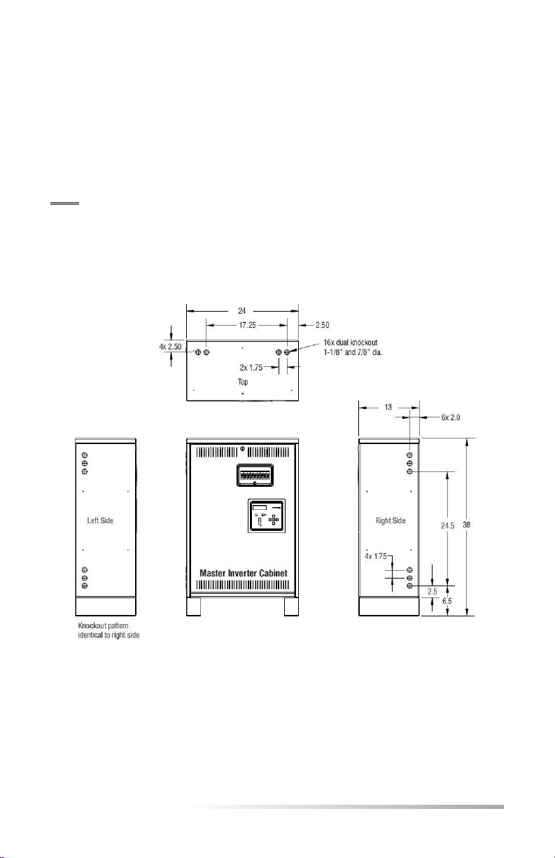
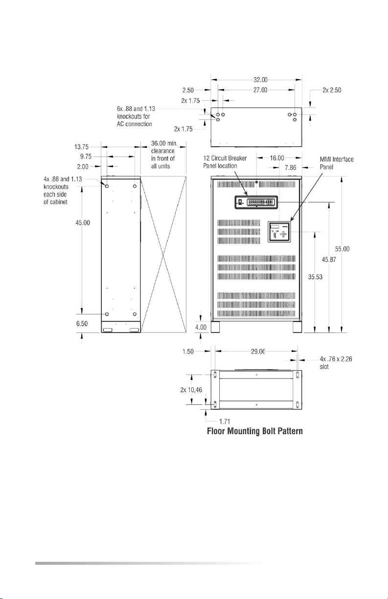
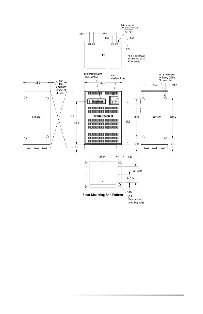
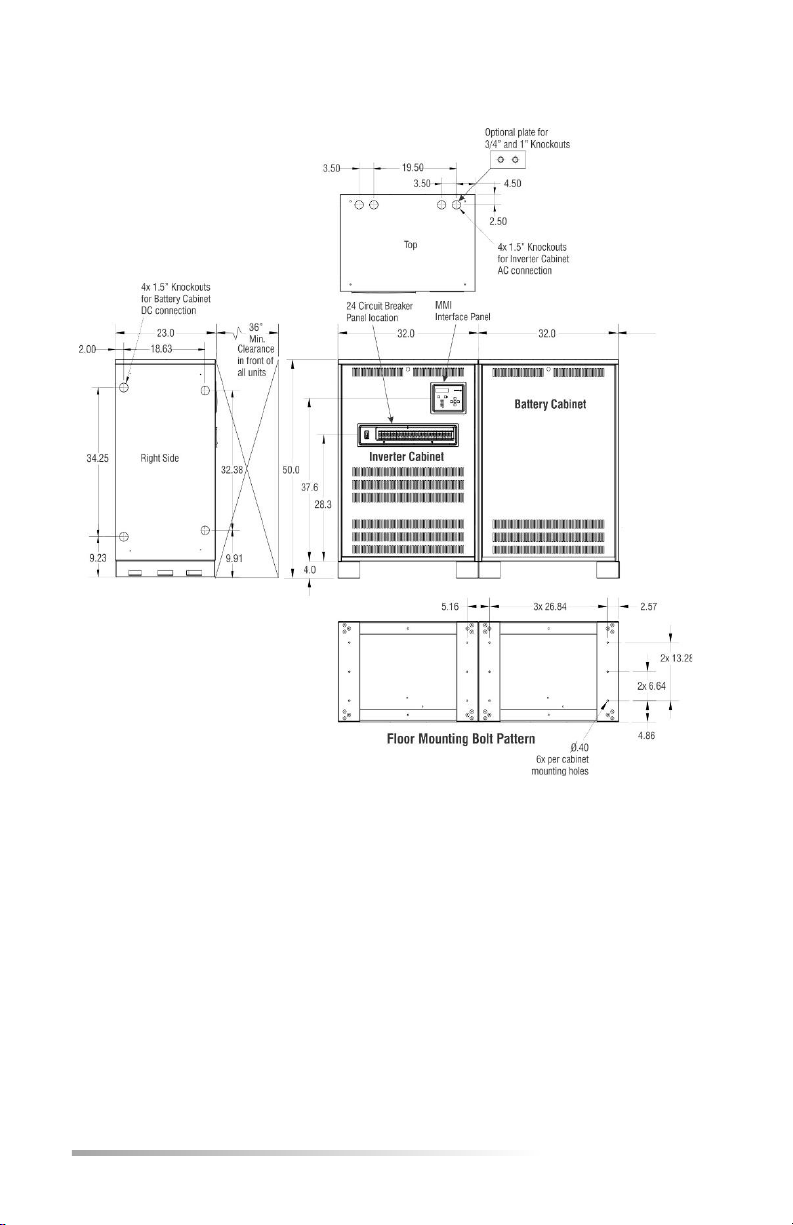
This product was designed having the electrical installer in mind. Batteries are Front
Access type which simply slide into the cabinet and connect with Busbar jumpers. They
are easy to install, safe and less prone to installation errors. The AC connections are also
easily made with the contractor landing the inputs and outputs to either Circuit
Breakers, terminals of busbars. Contractor piping for conduit is easily accomplished with
multi-sized knockouts on both sides and tops of the cabinet so wires can easily run into
the cabinet and connected to ground bars, neutral bars and circuit breakers.
The machine has an attractive Powder Painted 14 gauge Cold Rolled Steel construction
with no visible outside bolts or rivets. Internally, it has all galvanized or painted steel
parts for all the modules and shelves that resist corrosion and provide durability and
high quality.
1.2 Electrical Design Features
Through the use of Pulse Width Modulation (PWM) and the latest IGBT and MOSFET
technology, the E3-MAC Series can produce a pure sine-wave output which is
compatible with all types of lighting loads. A high crest factor of up to 4X is extremely
beneficial for high-inrush loads and also ideal for bringing Normally-Off lighting loads on
from a cold start. Since the active PWM regulation scheme produces a very low THD
waveform, the E3-MAC Series can power up even the most demanding loads driving its
output with power factor capabilities ranging from 0.5 leading to 0.5 lagging.
Adding to the versatility are the multiple output types of Normally-On, Normally-Off
and Switched. The batteries are charged by a temperature compensated charger
integrated into a bi-directional converter. A three-rate charging scheme and bi-
directional converter topology ensures maximum float life and minimal ripple current on
the batteries.
E3-MAC SERIES | 3

WARNING –The maximum storage time from shipment to initial
charge is 6 months for batteries stored at ambient temperatures no
warmer than 77°F (25°C). For storage temperatures greater than
77°F (25°C) the batteries must be recharged one (1) month sooner
for every 5°F (3°C) increase above 77°F (25°C).
2.0 RECEIVING AND STORAGE
2.1 Inspection
The E3-MAC Series central inverter and batteries are shipped together unless specified
with the “ship-less batteries” option code(-UP). Upon arrival, please inspect the
contents to ensure that no shipping damage has occurred. This is especially important
with batteries –ensure that there are no cracks or leaks. If any damage has occurred,
notify the shipping carrier immediately and submit a damage claim.
WARNING - NEVER use a physically damaged battery as this may cause an unsafe
condition.
2.2 Storage
Storage temperature before the installation is critical for the battery life expectancy
and warranty. Store the system indoors in a clean, dry and cool location. Storage at
higher temperatures will result in accelerated rates of self-discharge and possible
deterioration of battery performance and life.
Storage times exceeding the above may result in plate sulfation, which may adversely
affect electrical performance and expected life.
Failure to install and charge the batteries as noted
VOIDS the battery’s warranty
DANGER -Batteries present a risk of electrical shock and high short circuit current. Do
not smoke, cause a flame or spark in the immediate area of the batteries. Use proper
lifting means when moving batteries and wear all appropriate safety clothing and
equipment.
4| INSTALLATION / OPERATION MANUAL

3.0 INSTALLATION
3.1 Location
NEC article 700 EMERGENCY CIRCUITS should be referenced for proper installation of a
central inverter system. Article 700 dictates that unit must be mounted in a permanent
location. Choose a cool dry place with normal ventilation and one which will allow easy
access for testing and maintenance. Avoid a location which could allow vandalism and
tampering. Avoid areas that would prohibit visual contact with the heads-up LED status
displays.
3.2 Operating Environment
Choose a location that is controlled between 20 and 30 °C for optimum battery life.
E3-MAC Series is UL924 listed between 20 and 30 °C due to the battery discharge
performance results. Colder temperatures decrease the batteries discharge duration (90
Minutes is required per UL924 and NEC Article 700) and warmer temperatures will
adversely affect battery life. The optimal temperature of the E3-MAC Series system will
be 25°C / 77°F and all measures should be made to keep the batteries in this
temperature zone. Temperature -vs- Life expectancy is shown below.
E3-MAC SERIES | 5

3.3 Ventilation
Because the E3-MAC Series uses a maintenance-free sealed valve regulated lead acid
(VRLA) battery, no special ventilation is required. Spaces normally occupied by humans
with either natural or forced ventilation allowing at least 1 to 2 air exchanges per hour is
recommended. Choose a mounting location that is clean and dust free. Do not install in
areas where there is particulate or high pollution degree from heavy industrial
machinery, corrosive chemicals or welding or plasma cutting environments etc.
3.4 Clearance
Air ventilation is through the front surface so there are no clearance requirements for
the top, back or sides of the cabinet. However, the NEC code does require an
unobstructed 3 ft. of clearance in front of the cabinet (i.e. electrical panels).
3.5Floor Preparation
The mounting floor should be smooth and level so that the cabinet is not skewed or
twisted which would prevent the systems front door from being easily removed. Final
system leveling should be accomplished by shimming the cabinets corners so that the
front door can easily be removed for service. Floor mounting holes are provided in the
cabinet’s base and will accommodate up to a 3/8” mounting bolt. All 4 mounting holes
should be secured with bolts due to the weights of the cabinet(s) and associated
batteries. We recommend concrete wedge anchors such as the Hilti brand Wedge
Anchor series Kwik Bolt TZ or equivalent.
3.6Cabinet Configurations
There are 4 cabinet sizes/configurations for the E3-MAC Series. Electrical Knock Outs
(EKO’s) are provided on three surfaces. Ensure all metal conduit is secured and
tightened creating a good connection to earth ground. Use an Ohm-Meter to check that
continuity between conduit and protective earth ground has been established.
Seismic bracing is available for the E3-MAC Series. Please see Isolite.com for details of
seismic dimensions and configurations.
Note –Cabinet sizes and construction may change due to optional features such as
mixed voltages which require Isolation Transformers and/or Auto-Transformers.
All systems are shipped with a Contractors Guide for each model. This should be
referred to in the installation process since there may be more details available.
WARNING –Drilling into cabinet may void warranty if metal filings causes unit failure.
6| INSTALLATION / OPERATION MANUAL

SIZE 1
1KW Model
3.6 Cabinet Configurations (cont.)
Size 1 1KW
Size 2 1.6KW, 2.2KW, 2.8KW, 3.0KW
Size 3 4.0KW, 5.0KW, 6.0KW
Size 4 8.0KW, 10.0KW, 12.5KW
Note –Standard cabinet configurations for all sizes are shown. Other cabinet
configurations may be used when optional features are provided such as mixed
Input/Output voltages which requires isolation or auto-type transformers. These options
require additional cabinet space which may increase size.
E3-MAC SERIES | 7

SIZE 2
1.6KW thru 3.0KW Models
8| INSTALLATION / OPERATION MANUAL

SIZE 3
4.0KW thru 6.0KW Models
E3-MAC SERIES | 9

SIZE 4
8.0 KW thru 12.5 KW Models
10 | INSTALLATION / OPERATION MANUAL

4.0 AC CONNECTIONS
WARNING –Only qualified personnel that are familiar with AC and DC installation
techniques and codes (such as an electrician) should perform the Installation.
WARNING –The E3-MAC Series contains lethal AC Voltages. Due to the hazard of high
voltage electrocution, always shut down all sources of power before you install,
maintain, or service the unit.
WARNING –Remove all rings, watches, and other jewelry before doing any electrical
service or installation work. Always wear protective clothing and personal protective
equipment (PPE) that is suitable such as eye protection when working near batteries.
NOTE - Always check the system’s rating label located on the cabinets left side interior wall
and also the system’s door.
Use copper wire only –read all warning labels provided in the cabinet!
4.1 Removing the AC Breaker cover
To access wiring to the breakers, remove the two ¼-20 bolts from the plastic breaker
cover with a 3/8 socket or nut driver.
Note - This cover conceals the wiring area and also provides a safety barrier so fingers
do not inadvertently touch live parts after installation. Always re-install the AC Breaker
cover to prevent accidental contact with live wires during routine maintenance.
4.2 Installing the Input Wires
1. Ensure that the System ON/OFF switch is in the OFF position before starting.
2. Ensure that the incoming feed AC voltage matches the voltage rating of the
model you have. Please refer to the systems rating plate label.
3. Ensure that the feed breaker from the panel has enough ampacity to allow for
the full rating of the input current required on the systems rating plate.
Once the Utilities AC input feed voltage and Feed breaker size is confirmed, connect
the utilities feed AC wires to the systems Input circuit breaker (UL489 rated for direct
connection), Terminal Block NEU (Neutral) and grounding terminal block (GND). Ensure
wire connections are secure to all connection points by briefly tugging the wires to
ensure a solid, secure connection with low continuity.
NOTE –AC Input wiring may have to be landed to a Terminal Block instead of the Input
Breaker if a Bypass Switch or Mixed Voltages are present on your system.
E3-MAC SERIES | 11

Output Circuit Breakers:
Wires can be landed directly to the circuit breakers since these are UL489
type which are approved for field wiring.
Maintenance Bypass Switch:
This option will have an input terminal block for landing the incoming AC feed
wires. Connect the incoming AC feed to this terminal block.
Trip Alarms:
This option uses an auxiliary contact on the side of the output breaker to
indicate to the controls that the circuit breaker has tripped.
Switched Output:
This option has a Switched Command which controls the Switched Output.
Switched Outputs are provided with Circuit Breakers.
4.3Installing the Output Wires
Connect the load wires to the Normally-On output terminal blocks. If your system has
output breakers, connection directly to these circuit breakers are permitted since these
are also UL489 rated. Other output configurations could include Normally-Off or
Switched outputs which also use circuit breakers as the connection points. Please refer
to your systems part number for your specific output configurations. Ensure that the
connections to these terminal blocks or breakers are secured by briefly tugging the
wires. See Section 7.4 thru 7.5 for further load type details.
NOTE –AC Input and AC output wires must be run in separate conduit or raceways per
NEC ARTICLE 700. Please ensure all codes and standards are observed.
NOTE –E3-MAC Series requires that the Neutral and Ground potential does not exceed
5 VAC for proper function. Anything above 5 VAC typically indicates that there may be
an issue such as grounding, inadequate conductor size or continuity. This should be
looked at immediately as it could cause a safety concern.
NOTE –Neutral and ground should never be tied together anywhere in the E3-MAC
Series. Always keep Neutral and Ground wires separate to ensure no shorts occur.
NOTE –Neutral (NEU) in the E3-MAC Series is common to both the Input and Output.
Never mix Neutrals for the building wiring (Non-Emergency) with the Emergency wiring.
Dedicated wiring is required by NEC code ARTICLE 700.
4.4Special Options
Custom units are available (Section 8 Specifications –Ordering Guide) and these may
cause the construction to differ from standard models.
12 | INSTALLATION / OPERATION MANUAL

SIZE 1
1KW Model
SIZE 1 - Can accommodate up to 8 output breakers without trip
alarms, 5 output breakers with trip alarms. Output circuit
breakers can be configured as Normally-On, Normally-Off and
Switched-Output types. See Ordering Guide in Section 8 for
your specific breaker configurations. Breaker type(s) quantity
may be limited due to other installed optional features.
E3-MAC SERIES | 13

SIZE 2
1.6KW thru 3.0KW Models
SIZE 2 - Can accommodate up to 12 output breakers without
trip alarms –8 output breakers with trip alarms. Output circuit
breakers can be configured as Normally-On, Normally-Off and
Switched-Output types. See Ordering Guide in Section 8 for
your specific breaker configurations. Breaker type(s) quantity
may be limited due to other installed optional features.
14 | INSTALLATION / OPERATION MANUAL

SIZE 3
4.0KW thru 6.0KW Models
SIZE 3 - Can accommodate up to 12 output breakers without
trip alarms –8 output breakers with trip alarms. Output circuit
breakers can be configured as Normally-On, Normally-Off and
Switched-Output types. See Ordering Guide in Section 8 for
your specific breaker configurations. Breaker type(s) quantity
may be limited due to other installed optional features.
E3-MAC SERIES | 15

SIZE 4
8.0 KW thru 12.5 KW Models
SIZE 4 - Can accommodate up to 24 output breakers without
trip alarms –18 output breakers with trip alarms. Output circuit
breakers can be configured as Normally-On, Normally-Off and
Switched-Output types. See Ordering Guide in Section 8 for
your specific breaker configurations. Breaker type(s) quantity
may be limited due to other installed optional features.
16 | INSTALLATION / OPERATION MANUAL

5.0 BATTERY AND DC CONNECTIONS
WARNING –Only qualified personnel that are familiar with AC and DC installation
techniques and codes (such as an electrician) should perform the Installation.
WARNING –Remove all rings, watches, and other jewelry before doing any electrical
service or installation work. Always wear protective clothing and personal protective
equipment (PPE) that is suitable such as eye protection when working near batteries.
WARNING - Batteries contain tremendous energy and can explode if short circuited.
Precautions should be taken to eliminate possible short circuits. Do not install batteries
until unit is completely mounted and secured in a permanent location with all conduit
and AC wiring connected.
5.1 Battery Inspection
Inspect the batteries for any physical damage such as cracks or any other sign of
leaking electrolyte. Batteries contain Sulfuric Acid which is highly corrosive. A leak from
a battery will cause an unsafe condition.
5.2 Battery Installation/Removal
Note - Always ensure that the DC Fuse(s) are removed before starting installation.
1. Load all the batteries onto the shelves. Ensure proper spacing between the
batteries so that Battery to Battery Jumper Bars can be installed (Step 4).
2. Connect Battery Cables that go from shelf to shelf.
3. Connect Battery Positive
4. Connect all Jumper Bars between batteries
5. Connect Battery Negative
6. Install Fuse(s) –see your model if applicable. Battery string fuses are required
when separate battery cabinets are used.
To remove the batteries, simply reverse the above steps.
5.3 DC Voltage of System
The DC string voltage for the E3-MAC Series varies by size. The required string voltage
is produced by connecting multiple 12V batteries in series. Please refer to the System
Specifications for your model in Section 8.
E3-MAC SERIES | 17

1KW
MODEL
Tools Required:
Torque Wrench
w/10mm socket
Note - Torque all
batteries to 40 in-
lbs.
Note - Ensure all
bolts contain the
Flat Washer and
Lock Washer on all
the interconnect
wires and buss
bars.
5.3 Battery Hardware
All battery hardware required for the installation comes with the system. When
installing the batteries and hardware, please ensure flat washers and lock washers are
used with each bolt. Ensure that the batteries jumper busbars are seated flat against the
surface of the batteries terminals before tightening and NEVER over-tighten the bolts by
ensuring that proper torque is applied to the bolts.
5.4 Battery Pre-Checks
All batteries are quality controlled and measured from the factory before shipping.
We recommend that additional measurements are made as a quick determination of
the batteries health before starting up the system. Measure all batteries in their resting
state and ensure that all batteries are within 0.10 VDC to 0.150 VDC from each other.
18 | INSTALLATION / OPERATION MANUAL

2.2 KW
4.0 KW
MODELS
2.8 KW
5.0 KW
MODELS
1.6 KW
MODEL
E3-MAC SERIES | 19

3.0 KW
6.0 KW
MODELS
8.0 KW
MODEL
20 | INSTALLATION / OPERATION MANUAL
Other manuals for E3-MAC Series
1
This manual suits for next models
11
Table of contents
Other Isolite Inverter manuals