ISOMAG ISOIL MV110 Operating instructions

110_EN_IT_IS_R3_1.00.0
OPERATING AND MAINTENANCE
MANUAL
MV110

Release number: 110_EN_IT_IS_R3_1.00.0
The characters of le name in bold type indicate the software version which the manual refers to; it is visualized at
the instrument start up, or by specic function on DIAGNOSTIC menu.
The reproduction of this manual and any supplied software is strictly forbidden.

110_EN_IT_IS_R3_1.00.0

The manufacturer guarantees only English text available on our web site www.isoil.com
110_EN_IT_IS_R3_1.00.0
1 di 79
INDICE
SAFETY INFORMATION __________________________________________________ 3
INTRODUCTION________________________________________________________ 3
SAFETY CONVENTION ___________________________________________________ 4
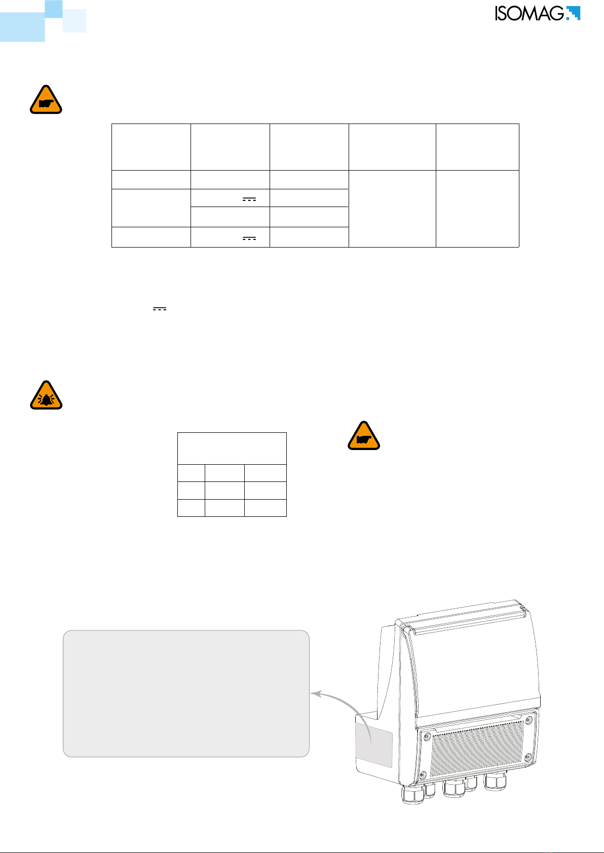
DATA PLATE ___________________________________________________________ 5
AMBIENT TEMPERATURE _________________________________________________ 5
TECHNICAL CHARACTERISTICS ___________________________________________ 5
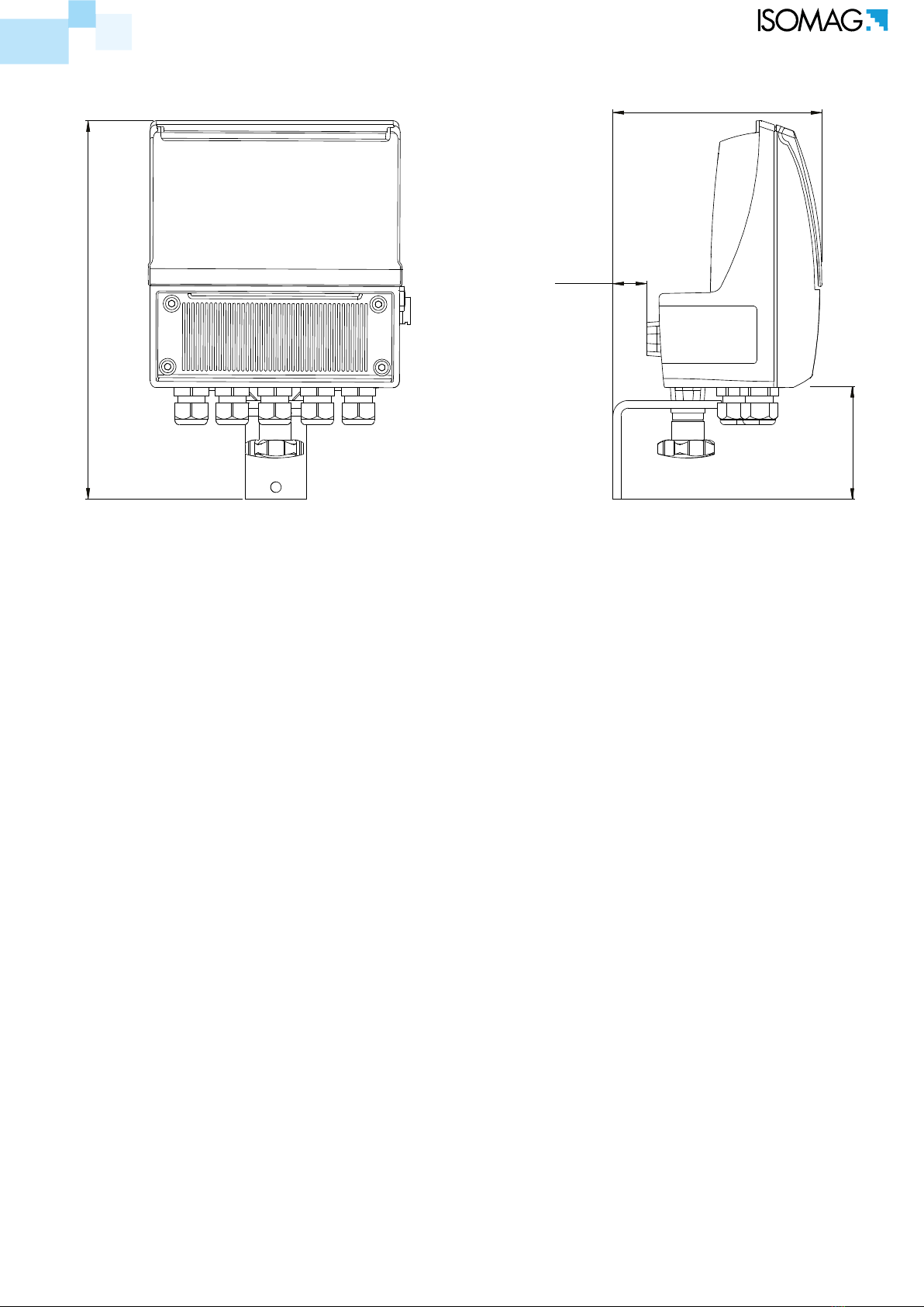
DIMENSIONS __________________________________________________________ 6
SEPARATE VERSION_____________________________________________________ 7
HORIZONTAL VERSION __________________________________________________ 8
VERTICAL VERSION _____________________________________________________ 8
MV110 CONSTRUCTION_________________________________________________ 10
INTERNAL LAYOUT ____________________________________________________ 11
ELECTRICAL CONNECTION AND GROUNDING INSTRUCTIONS ___________________ 12
DIGITAL INPUT ON/OFF OPERATION ______________________________________ 14
RS485 MODBUS MODULE (OPTIONAL) _____________________________________ 15
OUTPUTS WIRING _____________________________________________________ 15
DIGITAL OUTPUTS _____________________________________________________ 15
ANALOG OUTPUTS ____________________________________________________ 15
CONNECTORS MIL_____________________________________________________ 16
MEANING OF FLAGS____________________________________________________ 19
MEANING OF LED COLORS_______________________________________________ 19
ACCESS VIA KEYPAD ___________________________________________________ 20
ACCESS VIA MCP INTERFACE (VIRTUAL DISPLAY) ____________________________ 20
ACCESS TO THE CONFIGURATION MENU____________________________________ 20
FLOW RATE VISUALIZATION _____________________________________________ 21
FLOW RATE ALERT _____________________________________________________ 21
QUICK START MENU ___________________________________________________ 21
ACCESS CODE SET : MENU 13 SYSTEM______________________________________ 22
RESTRICTED ACCESS SET : MENU 13 SYSTEM _______________________________ 22

The manufacturer guarantees only English text available on our web site www.isoil.com
110_EN_IT_IS_R3_1.00.0
2 di 79
CONVERTER ACCESS CODE ______________________________________________ 22
FUNCTIONS MENU _____________________________________________________ 25
FUNCTIONS DESCRIPTION ______________________________________________ 29
MENU 1 - SENSOR _____________________________________________________ 30
MENU 2 - UNITS_______________________________________________________ 33
MENU 3 - SCALE _______________________________________________________ 35
MENU 4 - MEASURE ____________________________________________________ 37
MENU 5 - ALARMS _____________________________________________________ 39
MENU 6 - INPUTS______________________________________________________ 40
MENU 7 - OUTPUTS ____________________________________________________ 41
MENU 8 - COMMUNICATION _____________________________________________ 43
MV110 MODBUS PROTOCOL _____________________________________________ 43
MENU 9 - DISPLAY _____________________________________________________ 46
MENU 10 - DATA LOGGER _______________________________________________ 47
MENU 11 - FUNCTION __________________________________________________ 54
MENU 12 - DIAGNOSTIC ________________________________________________ 55
MENU 13 - SYSTEM ____________________________________________________ 58
MENU 14 - FILE (ONLY MCP) _____________________________________________ 64
MENU 15 - PROCESS DATA (ONLY MCP) ____________________________________ 66
METER DATA _________________________________________________________ 68
B.I.V. (BUILT-IN VERIFICATOR) __________________________________________ 69
SOFTWARE ISOBIV ____________________________________________________ 72
ERROR CODE TEST SYSTEM OF SENSOR ____________________________________ 73
ALARM MESSAGES (CAUSES AND ACTIONS TO BE TAKEN) ______________________ 74

The manufacturer guarantees only English text available on our web site www.isoil.com
110_EN_IT_IS_R3_1.00.0
3 di 79
SAFETY INFORMATION
INTRODUCTION
CONVERTER
SENSOR
These operating instructions and description of device functions are provided as part of the scope
of supply.
They could be modied without prior notice. The improper use, possible tampering of the instrument
or parts of it and substitutions of any components not original, renders the warranty automatically void.
The ow meter realizes a measure with liquids of conductivity greater than 5µS/cm in closed
conduits, and is composed of a converter (described in this manual) and a sensor (refer to the
specic manual).
The converter could be coupled directly on the sensor (compact version) or coupled to the sensor
by cable supplied with it (remote version).
Any use other than described in this manual aects the protection provided by the manufacturer
and compromises the safety of people and the entire measuring system and is, therefore, not
permitted. The manufacturer is not liable for damaged caused by improper or non-designated use.
Transport the measuring device to the measuring point in the original packaging. Do not remove
covers or caps until immediately before installation. In case of cartons packaging it is possible to
place one above the other but no more than three cartons. In case of wooden packaging do not
place one above the other.
Disposal of this product or parts of it must be carried out according to the local public or private
waste collection service regulations.
The converter must only be installed, connected and maintained by qualied and authorized
specialists (e.g. electrical technicians) in full compliance with the instructions in this Operating
Instruction, the applicable norms, legal regulations and certicates (depending on the application).

The manufacturer guarantees only English text available on our web site www.isoil.com
110_EN_IT_IS_R3_1.00.0
4 di 79
The specialists must have read and understood these Operating Instructions and must follow the
instructions it contains. The Operating Instructions provide detailed information about the converter. If
you are unclear on anything in these Operating Instructions, you must call the ISOIL service department.
The converter should only be installed after have veried technical data provided in these operating
instructions and on the data plate.
Specialists must take care during installation and use personal protective equipment as provided
by any related security plan or risk assessment.
Never mount or wire the converter while it is connected to the power supply and avoid any liquid contact
with the instrument’s internal components. To connect remove the terminals from the terminal block.
Before connecting the power supply check the functionality of the safety equipment.
Repairs may only be performed if a genuine spare parts kit is available and this repair work is
expressly permitted.
For the cleaning of the device use only a damp cloth, and for the maintenance/repairs contact the
service center (for details see the last page).
Before starting up the equipment please verify the following:
Power supply voltage must correspond to that specied on the data plate
Electric connections must be completed as described
Ground (earth) connections must be completed as specied
Verify periodically (every 3-4 months):
The power supply cables integrity, wiring and other connected electrical parts
The converter housing integrity
The suitable tightness of the sealing elements
The front panel integrity (display and keyboard)
The mechanical xing of the converter to the pipe or wall stand
DANGER ELECTRIC SHOCK
WARNING
PRECAUTIONS
ATTENTION
SAFETY CONVENTION

The manufacturer guarantees only English text available on our web site www.isoil.com
110_EN_IT_IS_R3_1.00.0
5 di 79
Power
supply
versions
Power
supply
voltage
Power
supply
frequency
Min
Power Max power
HV 100-240V~ 45-66HZ
1,5 W
(Sensor only)
5 W
(all Loads)
LV 24-36V //
24-36V~ 45-66HZ
LLV 12-48V //
AMBIENT
TEMPERATURE
Min* Max
°C -10 60
°F 14 140
MODEL: Convert Model
S/N: Serial Number of the converter
SUPPLY: Main power supply
Hz: Supply frequency (AC)
POWER: Maximum power consumption
IP: Protection grade
T: Operation temperature
COUPLING: Serial number of sensor coupled
ITEM: Free for user
The instrument label contain the following information:
Converter classication: class I, IP67/68 for aluminum and PA6 housing, installation category
(overvoltage) II, rated pollution degree 2.
Voltage variations must not exceed ±10% of the nominal one.
Input/output insulated up to 500V.
The output 4-20mA (optional) is electrically connected to the ON/OFF outputs and the output
power supply (24V ).
Version LV/LLV : inrusch current < 20A
Version HV : inrusch current < 25A
The converter can be installed internally or externally
Altitude: from –200m to 4000m (from -656 to 6560 feet)
Humidity range: 0-100%
If the converter is supplied in compact version (converter over the sensor), consider the ambient
temperatures more restrictive, otherwise refer to the relevant manuals.
* For discontinuous use, a thermostat heat source installation may be necessary.
TECHNICAL CHARACTERISTICS
ElEctrical charactEristic
EnvironmEntal UsE conditions
data PlatE
ATTENTION
The battery will not be charged outside the
below limits :
T board MV110 < 0 °C
T board MV110 > 50 °C

The manufacturer guarantees only English text available on our web site www.isoil.com
110_EN_IT_IS_R3_1.00.0
6 di 79
DIMENSIONS
200.0
114.0 164.0
167.0
114.0
176.0
290.0
195.0

The manufacturer guarantees only English text available on our web site www.isoil.com
110_EN_IT_IS_R3_1.00.0
7 di 79
136.5
22.5
252.0
76
sEParatE vErsion

The manufacturer guarantees only English text available on our web site www.isoil.com
110_EN_IT_IS_R3_1.00.0
8 di 79
200.0
144.0 56.0
270.0
87.0
75.0
horizontal vErsion
vErtical vErsion
JUCTION BOX
JUCTION BOX
JUCTION BOX JUCTION BOX

The manufacturer guarantees only English text available on our web site www.isoil.com
110_EN_IT_IS_R3_1.00.0
9 di 79
1
1
3
3
1
4
5
2
2
2
2
To guarantee the housing’s IP degree the following torques are required:
TORQUES
Housing
screw (1)
Cover terminal
block screw (2)
Fixing
Display
Frame
PCB
Screw
Version
Cap (3)
Cable
Glands (4)
Cap
USB-B (5)
ALUMINIUM
HOUSING 6 Nm 5.5 Nm 3 Nm 0.8 Nm 8 Nm 4 Nm 4 Nm
PLASTIC
HOUSING 2 Nm 2 Nm 2.5 Nm 0.8 Nm 7 Nm 4 Nm 4 Nm

The manufacturer guarantees only English text available on our web site www.isoil.com
110_EN_IT_IS_R3_1.00.0
10 di 79
5
1
2
3
6
9
10
11
12
14
17
18
20
21
22
19
7
4
24
15
13
23
16
8
TERMINAL BLOCK COVER
MAIN HOUSING COVER
PCB MV110
MAIN HOUSING
MV110 CONSTRUCTION
POS.
DESCRIPTION
PA6 VERSION ALUMINIUM VERSION
1SCREW M4x12 SCREW M5x12
2GROWER Ø4 GROWER Ø5
3TERMINAL BLOCK COVER TERMINAL BLOCK COVER
4O-RING-4400
5PROTECTION COVER
6HOUSING COVER HOUSING COVER
7ORING-4700
8ORING-117x3
9DISPLAY
10 FIXING DISPLAY FRAME (MATERIAL PA06)
11 SELF-TAPPING SCREW 4x10 TRILOBO SCREW 4x10
12 SELF-TAPPING SCREW 4x10 TRILOBO SCREW 4x10
13 PCB MV110
14 PG9 CAP
15 LITHIUM BATTERY
16 ANTICONDESE CAP
17 PA6 MAIN HOUSING ALUMINIUM MAIN HOUSING
18 GROWER Ø4 GROWER Ø5
19 SCREW M4x12 SCREW M5x12
20 O-RING-155
21 VERSION CAP (MATERIAL PA06)
22 SCREW M6x16
23 GROWER Ø6
24 PG11 CABLE GLAND

The manufacturer guarantees only English text available on our web site www.isoil.com
110_EN_IT_IS_R3_1.00.0
11 di 79
1 2
ON
MINI USB-B
POWER SUPPLY BOARD
TERMINAL BLOCKS
MAIN POWER
SUPPLY
INTERNAL LAYOUT
POWER SUPPLY CABLE
Remove the main housing cover by removing the 4 screws as shown here below.
Internal Converter vIews

The manufacturer guarantees only English text available on our web site www.isoil.com
110_EN_IT_IS_R3_1.00.0
12 di 79
ELECTRICAL CONNECTION AND GROUNDING INSTRUCTIONS
Always ensure that the converter and the sensor are grounded (earthed) correctly. The grounding
of the sensor and converter must ensure that the instrument and liquid are equipotential.
Before connecting the power supply, verify that the mains voltage is within the limits indicated on
data plate.
For the connections use only approved conductors, with re-proof properties, whose section varies
from 0.25mm2 to 1.50mm2, based on distance/power; additionally x the power supply wires with
a additional fastening system located close to the terminal.
The power supply line must be equipped with an external protection for overload current (fuse or
automatic line breaker).
Provide in close proximity the converter a circuit breaker easily accessible for the operator and clearly
identied; whose symbols must conform to the electrical safety and local electrical requirements.
Ensure that the component complies with the requirements of the standard for electrical safety
distance.
Check chemical compatibility of materials used in the connection security systems in order to
minimize electrochemical corrosion. In the aluminum housing it should avoid direct contact between
the ground connection cable and the aluminum housing. It is therefore recommended to connect
the safety ground cable, by placing it between the washer and the metal bracket on the related
terminal or use an eyelet terminal crimped on the ground protection cable.
The sensor, hardwired inputs and outputs are connected to the converter through terminal blocks
located inside the converter.
To locate the terminal block loosen the 4 screws on the terminal block cover. When the front cover
is lifted, the terminal block is visible. The terminal block is the hardwire connection of the converter
to external equipment, including the sensor.
The following pages give informations on the terminal block numbering, and the respective connecting
of the sensor cables, and inputs/outputs.
N(-)
L(+)
ORING 4700
COVER
SCREW
GROWER

The manufacturer guarantees only English text available on our web site www.isoil.com
110_EN_IT_IS_R3_1.00.0
13 di 79
321 4
272829 26
232425 22 21 20
171819 16 15 14
13 12 11
OUT2 C
OUT1 C
OUT 1-2 E
OUT2 (+) 4-20
OUT1 (+) 4-20
OUT1-2 (-) 4-20
E1
E2
CSH*
B
RS485
A
SH*
4-20 OUTPUTS
+24V
0V
SH*
DIGITAL OUTPUTS
IN1 +
DIGITAL
INPUTS
IN1 -
C1
COILS
C2 SH*
L (+)
N( - )
POWER SUPPLY
ELECTRODES
SH*
0V
Sudden movements of the electrodes cable could introduce noise.
ELECTRICAL CONNECTION CONVERTER- SENSOR
*SH = SHIELD OF CABLE internally connected to ground.

The manufacturer guarantees only English text available on our web site www.isoil.com
110_EN_IT_IS_R3_1.00.0
14 di 79
0-1.5V
3-40V
Block Totalizers
Totalizers Active
3-40V
0-1.5V
T
Reset
Tmin=100ms
Block
0-1.5V
3-40V
Scale 2
Scale 1
<18v
18-30V
Measure blocked
Measure
10KΩ
3-40Vdc (ON)
0/1.5Vdc (OFF)
15(+)
16(+)
10KΩ
16
22
10KΩ 15
21
+24
-0
DIGITAL INPUT ON/OFF OPERATION
POS. 6.1 see page 26 (T+; total direct positive set on)
POS. 6.2 see page 26 (P+; partial direct positive set on)
POS. 6.3 see page 26 (T-; total direct negative set on)
POS. 6.4 see page 26 (P-; total direct negative set on)
EXTERNAL POWER SUPPLY INTERNAL POWER SUPPLY
BLOCK TOTALIZERS
RANGE CHANGE
MEASURE LOCK
RESET TOTALIZERS
SAMPLE RATE Tmin
10HZ 220ms
20HZ 110ms
50HZ 45ms
MUST BE
T > Tmin
Necessary conditions for enabling the function
POS. 6.5 see page 26 (Totalizer counting lock command set on)
Necessary conditions for enabling the function
POS. 6.8 see page 26 (Range change set on)
Necessary conditions for enabling the function
POS. 6.6 see page 26 (Totalizer counting lock command set on)

The manufacturer guarantees only English text available on our web site www.isoil.com
110_EN_IT_IS_R3_1.00.0
15 di 79
18 OUT 1(+)
19 OUT 2(+)
17 (COM. OUT 1-2)
mA
24 OUT 1(+)
25 OUT 2(+)
23 (COM. 4-20 OUT 1-2)
OUTPUTS WIRING
DIGITAL OUTPUTS
ANALOG OUTPUTS
Opto-insulated output with oating collector and emitter
terminals freely connectable
Maximum switching voltage: 40V
Maximum switching current: 150mA
Maximum saturation voltage between collector and emitter
@150mA: 1.2V
Maximum switching frequency (load on the collector or emitter,
RL=470, VOUT=24V ): 1250Hz
Maximum reverse current bearable on the input during and
accidental polarity reversion (VEC): 100mA
Insulation from other secondary circuits: 500V
Opto-insulated output
Maximum load: 1000Ω
Maximum voltage without load: 27V
Refresh frequency is the same of the sample frequency of the
connected sensor
Protected against persistent over voltages to maximum 30V
RS485 MODBUS MODULE (OPTIONAL)
1 2
ON
1 2
ON
272829 26
B
RS485
A
SH
PC
0V
Positioning to ‘ON’ the termination switches 1 and 2, a 120Ω résistance is activated in the RS458 circuit (see
terminal block).
TERMINATION
SWITCH
TERMINAL BLOCK

The manufacturer guarantees only English text available on our web site www.isoil.com
110_EN_IT_IS_R3_1.00.0
16 di 79
CONNECTORS MIL
THE following are the links of the MIL connectors IP68
C from terminal L power converter (+ dc)
A from terminal N power converter (-dc)
B from terminal GROUND Power Converter
Connector
4 poles
Connector
10 poles
Connector
6 poles
1. Contact B from terminal 24 of the converter (Out1 4-20 +)
2. Contact A from terminal 25 of the converter (Out2 4-20 +)
3. Contact H from terminal 23 of the converter (Out1-2 4-20 -)
4. Contact C from terminal 21 of the converter (+ 24V)
5. Contact J from terminal 22 of the converter (0V)
6. Contact K from terminal 15 of the inverter (IN1 +)
7. Contact G from terminal 16 of the converter (IN1-)
8. Contact D from terminal 19 of the converter (C Out2)
9. Contact E from terminal 18 of the converter (Out1 C)
10. Contact F from terminal 17 of the converter (Out1-2 E)
11. Contact C from terminal 28 of the converter (RS485 A)
12. Contact J from terminal 29 of the converter (RS485 B)
NB: the connections 4 and 5 exclude the use
connections 11 and 12.
POWER SUPPLY
INPUT/OUTPUT
A contact from terminal 1 of the converter (electrode 1)
Contact F from terminal 2 of the converter (electrode 2)
Contact And from terminal 3 of the converter (COM. Elec.)
Contact B from terminal 13 of the converter (COIL 1)
Contact C from terminal 12 of the converter (COIL 2)
Contact D from terminal 4 and 11 of converter
(SHIELD electrodes - COILS)
SENSOR SIGNALS
D
A
C
B
A HB
C
J
K
G
D
E
F
F
A
E
B
D
C
NOTE: Military Connector 6 poles for sensor converter only provided in the separate version of the converter.

The manufacturer guarantees only English text available on our web site www.isoil.com
110_EN_IT_IS_R3_1.00.0
17 di 79
The direct exposure of the converter to the solar rays, could damage the liquid crystal display.
The visualization pages can be change according to instrument’s setup.
Flow rate trend
Flow rate value
Unit of measure
Flow rate direction +/-
Flag
Flow Speed
% Full Scale
n° ALARM
Flow rate value
Flow rate value
Direct Total Totalizer
Direct Partial Totalizer
Flow rate value
Reverse Total Totalizer
Reverse Partial Totalizer
Flow rate value
Totalizer Total Net
Totalizer Partial Net
Flow rate value
Direct Total Totalizer
Direct Partial Totalizer
Inverse Total Totalizer
Inverse Partial Totalizer
START VISUALIZATION PAGES
Push to change visualization
Table of contents
Other ISOMAG Media Converter manuals
Popular Media Converter manuals by other brands

Pico Macom
Pico Macom XUV Specifications

HIK VISION
HIK VISION DS-6900UDI user manual

Precision Digital Corporation
Precision Digital Corporation PDA1500 Series instruction manual

Speaka Professional
Speaka Professional SP-HD/SD-01 operating instructions

GSS
GSS PTDT 1000 Assembly instructions

Konica Minolta
Konica Minolta ZCW-100 instruction manual

GUSTARD
GUSTARD R26 user manual

Atlona
Atlona OmniStream 112 installation guide

AJA
AJA 12GDA Installation and operation guide

Videotec
Videotec VD816PR operating instructions

PCB Piezotronics
PCB Piezotronics Vibration Division 682A09 manual

Pro-Ject Audio Systems
Pro-Ject Audio Systems DAC Box RS Instructions for use